1
Advanced Information
Assurance Handbook
Chris May
Marie Baker
Derek Gabbard
Travis Good
Galen Grimes
Mark Holmgren
Richard Nolan
Robert Nowak
Sean Pennline
March 2004
®
CERT /CC Training and Education Center
Handbook
CMU/SEI-2004-HB-001
Unlimited distribution subject to the copyright.
Pittsburgh, PA 15213-3890
Advanced Information
Assurance Handbook
CMU/SEI-2004-HB-001
Chris May
Marie Baker
Derek Gabbard
Travis Good
Galen Grimes
Mark Holmgren
Richard Nolan
Robert Nowak
Sean Pennline
March 2004
®
CERT /CC Training and Education Center
Unlimited distribution subject to the copyright.
This work is sponsored by the Commander, United States Army Reserve (USAR) Information Operations Command and
USAR EIO.
This work is sponsored by the U.S. Department of Defense.
The Software Engineering Institute is a federally funded research and development center sponsored by the U.S.
Department of Defense.
Copyright 2004 by Carnegie Mellon University.
NO WARRANTY
THIS CARNEGIE MELLON UNIVERSITY AND SOFTWARE ENGINEERING INSTITUTE MATERIAL IS
FURNISHED ON AN "AS-IS" BASIS. CARNEGIE MELLON UNIVERSITY MAKES NO WARRANTIES OF ANY
KIND, EITHER EXPRESSED OR IMPLIED, AS TO ANY MATTER INCLUDING, BUT NOT LIMITED TO,
WARRANTY OF FITNESS FOR PURPOSE OR MERCHANTABILITY, EXCLUSIVITY, OR RESULTS OBTAINED
FROM USE OF THE MATERIAL. CARNEGIE MELLON UNIVERSITY DOES NOT MAKE ANY WARRANTY OF
ANY KIND WITH RESPECT TO FREEDOM FROM PATENT, TRADEMARK, OR COPYRIGHT INFRINGEMENT.
Use of any trademarks in this report is not intended in any way to infringe on the rights of the trademark holder.
Internal use. Permission to reproduce this document and to prepare derivative works from this document for internal use is
granted, provided the copyright and “No Warranty” statements are included with all reproductions and derivative works.
External use. Requests for permission to reproduce this document or prepare derivative works of this document for external
and commercial use should be addressed to the SEI Licensing Agent.
This work was created in the performance of Federal Government Contract Number F19628-00-C-0003 with Carnegie
Mellon University for the operation of the Software Engineering Institute, a federally funded research and development
center. The Government of the United States has a royalty-free government-purpose license to use, duplicate, or disclose the
work, in whole or in part and in any manner, and to have or permit others to do so, for government purposes pursuant to the
copyright license under the clause at 252.227-7013.
For information about purchasing paper copies of SEI reports, please visit the publications portion of our Web site
(http://www.sei.cmu.edu/publications/pubweb.html).
The authors gratefully acknowledge the talents of Laura Bentrem and Pamela Williams for
their technical editing contributions.
Contents
1 Host System Hardening and Availability Monitoring ......................................................1
1.1 Instructional Objectives .......................................................................................2
1.2
Overview .............................................................................................................3
1.3
Best Practices for Hardening Host Systems .......................................................4
1.3.1
Minimization ...........................................................................................5
1.3.2
Patch Management ................................................................................5
1.3.3
Isolation of Services ...............................................................................6
1.3.4
Redundant Servers ................................................................................6
1.3.5
Authentication ........................................................................................7
1.3.6
Changing Weak Default Settings ...........................................................7
1.3.7
Accountability .........................................................................................8
1.3.8
Controlling Network Traffic.....................................................................8
1.3.9
Backing Up Data ....................................................................................8
1.3.10 Physical Security....................................................................................9
1.4
1.5
1.6
1.7
Hardening Windows 2000 Systems ..................................................................10
1.4.1
Automated Scanning Tools ..................................................................10
1.4.2
Review Online Information About Windows Vulnerabilities .................11
1.4.3
Removing Unnecessary Features and Applications ............................12
1.4.4
Patch Management ..............................................................................15
1.4.5
Hardening Windows Services ..............................................................17
1.4.6
Group Policy and Active Directory .......................................................19
1.4.7
Security Configuration Toolset and Security Templates......................24
1.4.8
Harden Internet Information Services (IIS) ..........................................28
1.4.9
Host-Based Firewalls ...........................................................................35
Hardening Red Hat Linux Systems...................................................................39
1.5.1
Vulnerability Scanners Explained ........................................................39
1.5.2
Minimizing with Red Hat Package Manager ........................................46
1.5.3
Patch Management for Red Hat Linux Systems with Up2date............48
1.5.4
Securing Red Hat Linux Services ........................................................50
1.5.5
Bastille-Linux ........................................................................................54
1.5.6
IPtables Firewall...................................................................................58
System Availability Monitoring Tools ................................................................63
1.6.1
Nagios ..................................................................................................64
1.6.2
How Nagios Works...............................................................................65
Summary...........................................................................................................66
CMU/SEI-2004-HB-001
i
1.8
2
Review Questions .............................................................................................67
Firewalls and Network Access Controls.................................................................69
2.1 Instructional Objectives .....................................................................................70
2.2
Overview ...........................................................................................................71
2.3
Purpose of Filtering and Network Access Controls...........................................72
2.4
Review of Firewalls and Packet Filtering ..........................................................73
2.5
2.4.1
Stateless and Stateful Packet Filtering ................................................74
2.4.2
Why Firewalls Are Important ................................................................75
2.4.3
How Firewalls Make Packet Filtering Decisions ..................................76
IPTables (Netfilter for Linux) .............................................................................79
2.5.1
2.6
2.7
2.8
2.9
IPTables Rules .....................................................................................81
Demilitarized Zones (DMZs) .............................................................................85
2.6.1
Preparation and Implementation for DMZs ..........................................85
2.6.2
Graphical Representation of a DMZ ....................................................88
2.6.3
Recommended DMZ Configurations....................................................89
Routers ..............................................................................................................91
2.7.1
Routers as Packet Filters .....................................................................91
2.7.2
Ingress and Egress Filtering ................................................................92
Application Filtering and Access Controls on Individual Hosts .........................93
2.8.1
2.8.2
TCP Wrappers .....................................................................................93
Application-Based Authentication and Filtering with Various
Applications ..........................................................................................94
2.8.3
Configuring Built-In Access Controls in Services.................................96
Packet Filtering Above Layer 4 .........................................................................97
2.9.1
Snort-Inline ...........................................................................................98
2.9.2
IPSec Access Controls.......................................................................101
2.9.3
Proxy Filtering ....................................................................................109
2.10 Pros and Cons of Firewall and Network Access Controls ..............................115
2.10.1 Pros ....................................................................................................115
2.10.2 Cons ...................................................................................................116
2.11 Summary .........................................................................................................117
2.12 Review Questions ...........................................................................................118
3
ii
Intrusion Detection..................................................................................................119
3.1 Instructional Objectives ...................................................................................120
3.2
Overview .........................................................................................................121
3.3
Review of Intrusion Detection Systems ..........................................................122
3.3.1
What Is an Intrusion Detection System?............................................122
3.3.2
Intrusion Analysis Architecture...........................................................123
3.3.3
Types of IDS: Signature and Anomaly...............................................124
CMU/SEI-2004-HB-001
3.4
3.5
3.6
4
Snort................................................................................................................126
3.4.1
Snort Features ...................................................................................126
3.4.2
Snort Sensor Architecture ..................................................................128
3.4.3
Snort Advantages...............................................................................131
3.4.4
Snort Disadvantages..........................................................................133
Snort Add-Ons and Plug-Ins ...........................................................................137
3.5.1
Analysis Console for Intrusion Databases (ACID) .............................139
3.5.2
IDScenter ...........................................................................................141
3.5.3
PureSecure ........................................................................................147
3.5.4
Tripwire...............................................................................................149
3.5.5
LANguard System Integrity Monitor (SIM) .........................................154
Deploying the IDS ...........................................................................................159
3.6.1
IDS Deployment Problem 1 ...............................................................160
3.6.2
IDS Deployment Problem 2 ...............................................................162
3.6.3
IDS Deployment Problem 3 ...............................................................165
3.6.4
IDS Deployment Problem 4 ...............................................................166
3.7
Summary.........................................................................................................169
3.8
Review Questions ...........................................................................................170
Synchronization and Remote Logging .................................................................171
4.1 Instructional Objectives ...................................................................................172
4.2
Overview .........................................................................................................173
4.3
Computer Forensics........................................................................................174
4.4
Logging............................................................................................................176
4.5
4.4.1
Identify the Data to Be Captured Using Logging Mechanisms;
Determine What Data Is Most Useful to Collect ................................177
4.4.2
4.4.3
For All Data Categories, Capture Alerts and Any Reported Errors ...181
Determine Whether the Logging Mechanisms Provided with Your
Systems Sufficiently Capture the Required Information ....................181
4.4.4
Review the Logs.................................................................................182
4.4.5
Store and Secure Logged Data .........................................................182
Remote Logging..............................................................................................185
4.5.1
Decide How Actively to Monitor the Various Kinds of Logged Data ..185
4.5.2
Protect Logs to Ensure That They Are Reliable ................................186
4.5.3
4.5.4
Document a Management Plan for Handling Log Files .....................187
Protect Data Collection Mechanisms and Their Outputs to Ensure
That They Are Reliable ......................................................................189
4.5.5
Review Outputs Regularly to Understand What Is Expected and
What Is Abnormal...............................................................................189
Take into Account Special Data Collection and Handling
Procedures Required to Preserve Data as Evidence. .......................189
4.5.6
4.5.7
Consider Policy Issues.......................................................................190
4.5.8
Syslog Alert and Message Configurations .........................................191
CMU/SEI-2004-HB-001
iii
4.5.9
Linux/UNIX Syslogd Client .................................................................196
4.5.10 Syslog-ng Vs. Syslogd .......................................................................200
4.5.11 NTsyslog Daemon for Windows.........................................................206
4.5.12 Kiwi Syslog Daemon for Windows .....................................................210
4.6
Computer Time Synchronization.....................................................................215
4.7
Network Time Protocol (NTP) .........................................................................217
4.8
4.9
4.7.1
Configuring the NTPd Daemon (the ntp.conf File).............................221
4.7.2
Creating an SNTP Client in Windows 2000 .......................................223
4.7.3
Establishing an SNTP Server in Windows 2000 ................................223
4.7.4
Establishing an SNTP Server in a Windows Domain ........................225
Interacting with Log Files ................................................................................226
4.8.1
Analyzing IIS Log File Format............................................................227
4.8.2
Analyzing Tiny Personal Firewall Log File Format.............................230
4.8.3
Exporting Data from Log Files............................................................231
4.8.4
Reviewing Log Files ...........................................................................238
Freeware Log and Forensic Tools and Applications.......................................239
4.10 Identifying Attackers on Your Intranet .............................................................243
4.11 Identifying Attackers’ IP Addresses ................................................................245
4.11.1 Investigating the IP Address’s History on Your Network ...................245
4.11.2 Enumerating the Target with Network Tools......................................247
4.11.3 Examining Email Addresses ..............................................................252
4.12 Summary .........................................................................................................254
4.13 Review Questions ...........................................................................................255
Answers to Review Questions .......................................................................................257
Resources ........................................................................................................................259
References .......................................................................................................................263
iv
CMU/SEI-2004-HB-001
List of Figures
Figure 1:
Group Policy Microsoft Management Console (MMC) ....................................... 19
Figure 2:
IIS Lockdown Wizard Summary Report ............................................................. 32
Figure 3:
Tiny Personal Firewall Log ................................................................................. 38
Figure 4:
Adding a User in Nessus .................................................................................... 41
Figure 5:
Adding an SSL Certificate .................................................................................. 42
Figure 6:
Nessus Intro Screen ........................................................................................... 43
Figure 7:
Nessus Scan Progress Indicator ........................................................................ 44
Figure 8:
Nessus Scan Results ......................................................................................... 45
Figure 9:
Linux Taskbar with up2date Notification............................................................. 48
Figure 10:
Red Hat Network Update Tool (up2date) ........................................................... 49
Figure 11:
Contents of rc.d Directory................................................................................... 51
Figure 12:
Contents of init.d Directory ................................................................................. 51
Figure 13:
Contents of rc5.d Directory................................................................................. 51
Figure 14:
Output from chkconfig ........................................................................................ 52
Figure 15:
Bastille Intro Screen ........................................................................................... 55
Figure 16:
Host-Based IPtables Chains .............................................................................. 59
Figure 17:
Webmin IPtables Configuration .......................................................................... 60
Figure 18:
The Nmap Run Before Firewalling ..................................................................... 61
Figure 19:
Adding IPtables Rule with Webmin .................................................................... 61
Figure 20:
Setting the Default Policy for the INPUT Chain.................................................. 62
Figure 21:
The nmap Run After Firewalling ......................................................................... 62
Figure 22:
Nagios Web Interface ......................................................................................... 64
Figure 23:
Nagios Plug-in Architecture ................................................................................ 65
Figure 24:
Webmin IPTables Firewall Filtering Options ...................................................... 77
Figure 25:
Allowing TCP Port 10000 Inbound from 192.168.93.1/32.................................. 82
Figure 26:
Setting Outbound Restrictions to Port 10000; Destination to 192.168.93.1....... 82
Figure 27:
Creating Implicit “Drop” for Incoming and Outgoing Packets ............................. 83
Figure 28:
Pinging the Webmin Firewall Host ..................................................................... 83
Figure 29:
Telneting to the SSH Port................................................................................... 84
Figure 30:
Telneting to Port 10000 ...................................................................................... 84
Figure 31:
Example Rule from IPTables as Displayed by Webmin..................................... 89
Figure 32:
ICMP Traffic Destined for the Firewall................................................................ 90
CMU/SEI-2004-HB-001
v
Figure 33:
Ruleset for Management Traffic from Management Network to the DMZ.......... 90
Figure 34:
Packet Dropped by Snort Inline System............................................................. 99
Figure 35:
Packet Modified by Snort Inline System ............................................................. 99
Figure 36:
Local Security Settings ..................................................................................... 104
Figure 37:
Squid Proxy Server Icons ................................................................................. 111
Figure 38:
Ports and Networking in Squid Proxy Server ................................................... 112
Figure 39:
Edit ACL in Squid Proxy Server........................................................................ 112
Figure 40:
Edit Proxy Restriction in Squid Proxy Server ................................................... 113
Figure 41:
Changing Defaults to Allow Outbound Traffic in Squid Proxy Server .............. 113
Figure 42:
Ordering Proxy Restrictions in Squid Proxy Server.......................................... 114
Figure 43:
What a Browser Displays for a Blocked IP Address When Squid Proxy
Server Is Configured Correctly ......................................................................... 114
Figure 44:
Sample Snort Rule File..................................................................................... 132
Figure 45:
ACID Alert Listings ........................................................................................... 140
Figure 46:
ACID Attack Trend Analysis ............................................................................. 140
Figure 47:
IDScenter Network Variables Wizard ............................................................... 142
Figure 48:
IDScenter Preprocessor Wizard ....................................................................... 143
Figure 49:
IDScenter Output Plugin Wizard....................................................................... 144
Figure 50:
IDScenter Rules/Signatures Wizard ................................................................. 144
Figure 51:
IDScenter Online Update Wizard ..................................................................... 145
Figure 52:
The LANguard Scheduling Dialog Box ............................................................. 154
Figure 53:
LANguard Scan Job Settings ........................................................................... 157
Figure 54:
LANguard Scheduler ........................................................................................ 158
Figure 55:
Selecting Snort Rulesets in IDScenter ............................................................. 164
Figure 56:
Editing Individual Rules in IDScenter ............................................................... 164
Figure 57:
Registry Editor .................................................................................................. 168
Figure 58:
Example of a Syslog.conf File .......................................................................... 197
Figure 59:
Sample Config File ........................................................................................... 202
Figure 60:
NTsyslog Service Control Manager (Main Control Panel) ............................... 208
Figure 61:
NTsyslog Service Control Manager (Enter the Client Hosting NTsyslog) ........ 208
Figure 62:
NTsyslog (Syslog Server Settings)................................................................... 209
Figure 63:
NTsyslog (Security Settings) ............................................................................ 209
Figure 64:
Kiwi Syslog Daemon Setup .............................................................................. 212
Figure 65:
NetTime Interface (NetTime Options) .............................................................. 224
Figure 66:
NetTime Interface (Find a Time Server) ........................................................... 224
Figure 67:
Microsoft Notepad ............................................................................................ 232
Figure 68:
IIS Log Showing C-IP Address, User-Agent Field, and SC-Status .................. 246
Figure 69:
A "Whois" Search on the Domain CMU.EDU................................................... 248
vi
CMU/SEI-2004-HB-001
Figure 70:
Reverse IP Lookup on an IP Address .............................................................. 249
Figure 71:
Traceroute Showing “Hops” Required to Reach Target IP Address ................ 250
Figure 72:
Spoofed Email Header ..................................................................................... 252
CMU/SEI-2004-HB-001
vii
viii
CMU/SEI-2004-HB-001
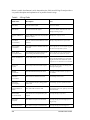
List of Tables
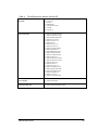
Table 1:
Tables Included in the IPTables Firewall and Their Associated Chains ............ 80
Table 2:
Rulesets That Must Be Written for Packet Filter(s) ............................................ 86
Table 3:
Files and Directories to Monitor........................................................................ 151
Table 4:
Files/Directories to Monitor with an IDS ........................................................... 155
Table 5:
Data Categories and Types of Data to Collect ................................................. 179
Table 6:
IIS Log Fields.................................................................................................... 228
Table 7:
Freeware Log and Forensic Tools and Applications ........................................ 239
CMU/SEI-2004-HB-001
ix
x
CMU/SEI-2004-HB-001
Abstract
This handbook is for technical staff members charged with administering and securing
information systems and networks. The first module briefly reviews some best practices for
securing host systems and covers specific techniques for securing Windows 2000 and Red
Hat Linux systems. It also discusses the importance of monitoring networked services to
make sure they are available to users and briefly introduces two software tools that can be
used for monitoring. The second module covers the importance of firewalls and provides
instructions for their configuration and deployment. The third module presents the many
tasks involved in using an intrusion detection system (IDS) on a network. Topics covered
include implementing IDSs on host computers and on networks, using Snort (the most
common open-source IDS), and interpreting and using the information gathered using an
IDS. The fourth and final module covers real-world skills and techniques for synchronizing
the time on networked computers from a central clock, collecting and securing information
for forensic analysis, and using a remote, centralized storage point for log data gathered from
multiple computers.
CMU/SEI-2004-HB-001
xi
xii
CMU/SEI-2004-HB-001
1 Host System Hardening and Availability Monitoring
Advanced Information Assurance
Module 1:
Host System Hardening and
Availability Monitoring
CERT® Education and Training
Software Engineering Institute
Carnegie Mellon University
Pittsburgh, PA 15213-3890
© 2003 Carnegie Mellon University
® CERT, CERT Coordination Center and Carnegie Mellon are registered in the
U.S. Patent and Trademark Office by Carnegie Mellon University
This module briefly reviews some best practices for securing host systems and then covers
specific techniques for hardening Windows 2000 and Red Hat Linux systems. It also
discusses the importance of conducting service availability monitoring and briefly introduces
two software tools for implementing it.
CMU/SEI-2004-HB-001
1
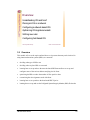
Instructional Objectives
List 5 high-level practices for securing host systems
Use specific scanning tools to determine initial
security posture of host systems
Use specific tools to update and patch operating
systems and applications
Use specific tools to harden security configurations
on host systems
Use specific tools to monitor availability of
network systems
© 2003 Carnegie Mellon University
Module 1: Host System Hardening and Availability Monitoring – slide 2
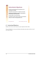
1.1 Instructional Objectives
Students will be able to do all of the above upon completion of this module.
2
CMU/SEI-2004-HB-001
Overview
Best practices for hardening host systems
Techniques for hardening Windows 2000 Systems
Techniques for hardening Red Hat Linux Systems
Tools for monitoring the availability of network
systems
© 2003 Carnegie Mellon University
Module 1: Host System Hardening and Availability Monitoring – slide 3
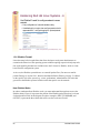
1.2 Overview
This module will cover the topics outlined above.
CMU/SEI-2004-HB-001
3
Best Practices for Hardening
Host Systems
Determine the initial security posture of system (via
automated scanning)
Minimize non-essential services, applications, and OS
features (Example: Web servers on user systems)
Make sure system has latest patches and hotfixes
available
© 2003 Carnegie Mellon University
Module 1: Host System Hardening and Availability Monitoring – slide 4
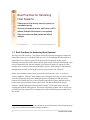
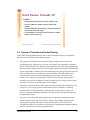
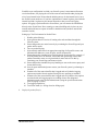
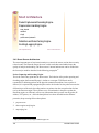
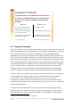
1.3 Best Practices for Hardening Host Systems
The topics covered in slides 4–7 are general security best practices that apply to almost any
kind of host system, be it a Windows Web server or a 3Com-managed Ethernet switch. It is
important to review these best practices as they provide a framework for the specific
hardening techniques that will be discussed later in the module. Host system hardening is one
critical component to the “defense in depth” goal. Defense in depth is a strategy in which
multiple layers of security measures (technologies, policies, and training) are implemented
throughout the network, increasing the overall security posture of the enterprise.
Before you can harden a host system, you must first find out what “state” it’s in from a
security standpoint. There are many manual ways of doing this, but using a security scanning
tool can help speed up the process. Although a plethora of commercial and open source
products are available, they vary in how accurately and effectively they depict the security
posture of the system with the results of their scans. The Microsoft Baseline Security
Analyzer1 and the LANguard Network Security Scanner2 will be used in this course for
scanning our Windows 2000 systems. The Nessus vulnerability scanner will be used to scan
our Red Hat Linux systems. These scanning tools will be described in greater detail later in
this module.
1
2
4
http://www.microsoft.com/technet/treeview/default.asp?url=/technet/security/tools/Tools/mbsahome.asp
http://www.gfi.com/downloads/downloads.asp?pid=8&lid=1
CMU/SEI-2004-HB-001
1.3.1 Minimization
The concept of minimization is paramount to the hardening process. Only essential
applications and operating system components should be loaded on host systems—especially
critical systems like servers. For example, Windows 2000 servers generally should not have
Microsoft Office loaded on them, and conversely, Windows XP workstations generally
should not have Internet Information Server (IIS) installed. Software vulnerabilities account
for a large percentage of the security incidents that occur. Thus, less software on a host
generally equates to less exploitation of software vulnerabilities.
1.3.2 Patch Management
Because software bugs are so common, it is essential that host system software be patched
effectively. Patch management is a real challenge, especially in very large enterprises. Keep
yourself informed about software vulnerabilities that impact your environment and
implement procedures for promptly updating your systems with good code. We’ll talk about
specific techniques and tools later in this module.
CMU/SEI-2004-HB-001
5
Best Practices for Hardening
Host Systems - 2
Isolate key services from each other (don’ t put all your
eggs in one basket)
• If resources allow, keep public services on separate
hosts
• For redundancy, place multiple essential servers
(DNS, domain controllers, etc.) on different
physical network segments
© 2003 Carnegie Mellon University
Module 1: Host System Hardening and Availability Monitoring – slide 5
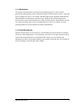
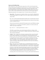
1.3.3 Isolation of Services
In conjunction with minimization, isolation of services is also a best practice for security. In
production environments, it’s best to isolate services (email, www, ftp, file/print, etc.) on
separate physical host systems. This way, if a software bug in a given service is exploited by
an intruder, the potential impact on other critical services would be limited. Also, if a patch is
applied for a specific service (for example, IIS) that requires a reboot of the system,
physically isolated services would be unaffected.
1.3.4 Redundant Servers
For some critical services like domain name servers (DNS) and Windows 2000 directory
services, it is a good idea to have redundant servers on multiple subnets. This can enhance
continuity of service in the event of a network outage.
6
CMU/SEI-2004-HB-001
Best Practices for Hardening
Host Systems - 3
Configure for strongest authentication available
• Multi-factor is best (however, plain old
username/password can be fairly secure, if
proper policies are implemented and enforced)
• Lock down weak default OS/Application
settings (Examples: Anonymous enumeration
and NTFS permissions on Windows 2000
systems)
© 2003 Carnegie Mellon University
Module 1: Host System Hardening and Availability Monitoring – slide 6
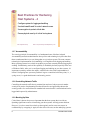
1.3.5 Authentication
Authentication is the process of verifying the account credentials (e.g., username and
password) of systems or users. It is essentially the gatekeeper for your systems and services,
ensuring that only those who have been explicitly permitted are granted access. Because
account credentials are so vital, they must be protected. Policies and technologies should be
implemented that keep these credentials secure and safe from prying eyes (or packet
sniffers)! Additionally, technologies should be implemented that verify the identity of the
user (or system) to a degree that’s acceptable to the organization. Multi-factor authentication
systems are becoming more common; users’ identities are verified by validating some
combination of something they know (i.e., username and password and/or P.I.N.), something
they have (i.e., PKI-enabled smart card), and something they are (i.e., biometrics-based
thumbprint scan). Plain old username and password is still the most widely used
authentication method and can be relatively secure if password policies (i.e., minimum
length, complexity, age) and account lockout policies are enforced.
1.3.6 Changing Weak Default Settings
Many operating systems and applications have some default settings that can open the door to
security breaches. For example, an intruder can connect to a specific default share on a
Windows 2000 system (IPC$) and learn a great deal about the system while providing no (in
this case null) authentication credentials. It is important to learn about these default
weaknesses and change the systems’ settings to make them more secure. Administrators
should stay current by reading technical security publications and Web sites like
http://www.cert.org.
CMU/SEI-2004-HB-001
7
Best Practices for Hardening
Host Systems - 4
Configure system for logging and auditing
Use host-based firewall to control network access
Use encryption to protect critical data
Ensure physical security of critical host systems
© 2003 Carnegie Mellon University
Module 1: Host System Hardening and Availability Monitoring – slide 7
1.3.7 Accountability
The security principle of accountability is a fundamental tenet of defense in depth.
Accountability means that administrators have policies and technologies in place that allow
them to understand who is (or was) doing what on a given host system. The most common
technological implementation of accountability is accomplished with logging and auditing.
Most operating systems have a built-in capability to perform extremely detailed logging and
auditing. Unfortunately, much of this capability is disabled by default (especially in the case
of Windows 2000). After you’ve configured logging and auditing on your host systems, it’s
important to routinely monitor the output—otherwise the value of the implementation is
limited. Configuring host systems to push their logs to a centralized collection point (i.e., a
syslog server) is a good administrative and security practice.
1.3.8 Controlling Network Traffic
Controlling the network traffic that is permitted into and out of a host system is another
security best practice. Implementing host-based firewalls can significantly enhance the
security posture of a network because unauthorized network traffic is minimized and can be
logged and inspected by administrators.
1.3.9 Backing Up Data
Critical data is almost always more important than the host systems that it resides on.
Spending significant resources in hardening your host systems will help protect this data.
However, it is also a smart idea to back up data regularly and in some cases ensure its
confidentiality by encrypting it. Again, the data is the real asset, not the underlying systems.
8
CMU/SEI-2004-HB-001
1.3.10 Physical Security
Finally, we would be remiss if we did not mention the importance of physical security. If an
intruder gains physical access to a host system, it won’t be long before he or she owns and
controls that system. Critical host systems like servers and other network infrastructure
equipment should be placed in secure facilities where only individuals with privileges (such
as administrators) can gain access.
CMU/SEI-2004-HB-001
9
Hardening Windows 2000 Systems
Determine the initial security posture of system
• Microsoft Baseline Security Analyzer (MBSA)
• Languard Network Security Scanner
• GRC.com’ s Shields Up!!
Demo: Microsoft Baseline Security Analyzer (MBSA)
© 2003 Carnegie Mellon University
Module 1: Host System Hardening and Availability Monitoring – slide 8
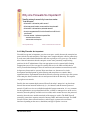
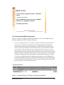
1.4 Hardening Windows 2000 Systems
As mentioned previously, there are numerous automated scanning tools available for
detecting vulnerabilities in Windows 2000 systems. This class will cover two of these tools,
both of them freeware. The slide also mentions Shields Up!!, an HTML-based Internet
scanner from GRC.com. This site can be somewhat helpful, as it shows how vulnerable a
Windows host is to Internet-based attacks.
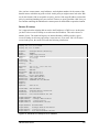
1.4.1 Automated Scanning Tools
The Microsoft Baseline Security Analyzer3 (MBSA) is a tool used to streamline identification
of security misconfigurations including missing patches and security updates. Scans can be
conducted on individual Windows machines or a specified range of machines—local or remote.
The MBSA has command line and graphical interfaces to perform scans on local or remote
Windows systems. A scan using this tool will identify configuration problems and
vulnerabilities in the following products:
1.
2.
3.
4.
5.
6.
3
Windows NT 4.0/2000/XP
Windows Server 2003
Internet Information Server (IIS)
SQL Server
Internet Explorer
Office 2000/2002
http://www.microsoft.com/technet/treeview/default.asp?url=/technet/security/tools/Tools/mbsahome.asp
10
CMU/SEI-2004-HB-001
Scans will also identify missing patches or security updates in the following products:
1.
2.
3.
4.
5.
6.
7.
Windows NT 4.0/2000/XP
Windows Server 2003
Internet Information Server (IIS)
SQL Server
Internet Explorer
Exchange
Windows Media Player
The MBSA uses a tool called HFNetChk that scans a machine and checks the patch status by
referring to an XML database maintained by Microsoft. The results from the scan will be stored in
an XML security report which will be displayed in the graphical user interface (GUI) in HTML.
LANguard Network Security Scanner (NSS)4 is a mature vulnerability scanning tool that
specializes in uncovering security issues with Windows-based systems—although it is
effective on other platforms as well. It has a user friendly GUI and can scan a single system
or multiple subnets. It is one of the fastest scanning tools available and has the capability to
control and push out Microsoft service packs, patches, and hotfixes to Windows-based
systems. Vulnerability scanning features are free; patching capabilities are only active for 30
days with the freeware version. (A license must be purchased to enable permanent patching
capabilities.) Care should be taken when scanning hosts with this tool, as it will very likely
cause intrusion detection systems to register alerts.
Using the tools mentioned briefly here will give you a fairly good understanding of the
security posture of your Windows 2000 systems.
1.4.2 Review Online Information About Windows Vulnerabilities
In addition to using scanning tools, it is also a good idea to review online information about
Windows vulnerabilities and hardening. The following are two highly recommended sources:
1.
The SANS/FBI Top 20 List, The Twenty Most Critical Internet Security Vulnerabilities, [SANS
03] – This regularly updated document offers a good, brief description of problems and suggested
hardening approaches.5
2.
The Microsoft guide Securing Windows 2000 Server [Microsoft 03c] – This excellent and very
comprehensive guide provides 11 chapters of solid information on hardening Windows 2000
Servers, both as host systems and in their role within an enterprise scenario environment.6
4
http://www.gfi.com/downloads/downloads.asp?pid=8&lid=1
http://www.sans.org/top20/top20.pdf
6
http://www.microsoft.com/technet/treeview/default.asp?url=/technet/security/prodtech/windows/secwin2k/default.asp
5
CMU/SEI-2004-HB-001
11
Hardening Windows 2000 Systems - 2
Remove unnecessary OS features and applications
• IIS, Outlook Express, Windows Media Player, Journal
Viewer, Games, Posix and OS2 subsystems, etc.
• Primarily concerned with minimizing servers
© 2003 Carnegie Mellon University
Module 1: Host System Hardening and Availability Monitoring – slide 9
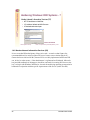
1.4.3 Removing Unnecessary Features and Applications
A typical load of Windows 2000 Server (and W2K Professional) has many unnecessary
features and applications that should be removed. Depending on the server’s role, Internet
Information Services (IIS) may or may not be required. IIS, Microsoft’s Web and ftp server
solution, has become legendary for the number of bugs associated with the software. If your
server’s role doesn’t require IIS, remove it!
Removing Internet Information Services
1. From the Start menu, select Settings > Control Panel > Add/Remove Programs >
Add/Remove Windows Components.
2. Uncheck the Internet Information Service box. If your system requires IIS, refer to
Harden Internet Information Services (IIS) on page 28 of this workbook.
Windows 2000 Servers should not have any applications designed for entertainment or clientlevel interaction installed. Follow the above procedure and remove any application of this
nature. Examples are games (like Solitaire), Windows Media Player, Journal Viewer, and
Netmeeting. Administrators should not be checking their email on production servers, so
Outlook Express should be removed as well. Removing Outlook Express is relatively
straightforward if Software Installation Services are controlled through Group Policy, but can
be rather complicated to remove on a stand-alone server—especially if you follow
Microsoft’s instructions.
The following procedure is the quickest way to remove Outlook Express from Windows
2000. This is not the Microsoft method; apparently, Microsoft doesn’t really want you to
12
CMU/SEI-2004-HB-001
remove Outlook Express at all. Your system must be formatted NTFS. This procedure will
also prevent the system file protection feature of Windows from restoring Outlook Express
files after they’ve been deleted.
Removing Outlook Express from Windows 2000 Server (Quick Method)
1. Open Windows Explorer and browse to the folder c:\Program Files\Outlook Express.
2.
Right click on that folder and select Properties. Select the Security tab and highlight
System in the list of users.
3.
Under Permissions, check the Deny box next to Full Access. Click OK. (Click OK again
if prompted with a warning message.)
4.
Now you can delete the contents of the Outlook Express folder. (Do not delete the
folder itself!)
5.
Browse to the folder c:\winnt\system32\dllcache\ and delete the file msimn.exe.
6.
From the Start menu, select Settings > Control Panel > Add/Remove Programs > Add/
Remove Windows Components. Uncheck the Outlook Express box and then click OK.
That’s it. You'll have an empty folder called Outlook Express, but the program will be gone
and your system will be that much safer. You may need to repeat this process if you apply a
new Service Pack, as it may reinstall the program.
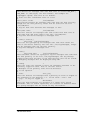
For legacy compatibility reasons, Microsoft built-in support for OS2 and Posix operating
systems. The OS2 and Posix subsystems in Windows 2000 can introduce security
vulnerabilities to the operating system. Therefore, it is recommended that these subsystems
be removed [NSA 03b].
CMU/SEI-2004-HB-001
13
Deleting Subsystem Executables
When deleting subsystem executables, remove the following files from the following folders
in this order:
•
C:\winnt\system32\dllcache (if present)
- os2.exe
- os2ss.exe
- os2srv.exe
•
C:\winnt\system32\
- os2.exe
- os2ss.exe
- os2srv.exe
- psxss.exe
- posix.exe
- psxdll.dll
- All Files in the \os2 folder, with the exception of the DLL folder and its contents. If
the modules in the \DLL folder are removed, functions such as Cmd.exe will fail.
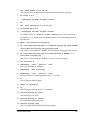
Deleting Subsystem Registry Key Values
Even if the subsystem executables have been removed, the subsystem could be reactivated if
related registry keys still exist. In addition to the above files, all registry keys related to the
subsystems must be removed.
1. Open the registry editor from the Start menu by selecting Run and typing “Regedt32” in
the Run window.
2. Browse to the following key values and remove the entries:
Hive: HKEY_LOCAL_MACHINE
Key: \System\CurrentControlSet\Control\Session Manager\Environment
Name: Os2LibPath
Entry: Delete entry
Hive: HKEY_LOCAL_MACHINE
Key: \System\CurrentControlSet\Control\Session Manager\Subsystems
Name: Optional
Entry: Delete entry
Hive: HKEY_LOCAL_MACHINE
Key: \System\CurrentControlSet\Control\Session Manager\Subsystems
Name: OS2 and POSIX
Entry: Delete entries for both OS2 and POSIX
14
CMU/SEI-2004-HB-001
Hardening Windows 2000 Systems - 3
Solutions for patch management (many—none perfect)
• Windows Update
• Microsoft Software Update Services (SUS)
• Many commercial products (Languard, Shavlik, etc.)
Demo: SUS
© 2003 Carnegie Mellon University
Module 1: Host System Hardening and Availability Monitoring – slide 10
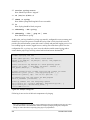
1.4.4 Patch Management
As mentioned previously, patching software bugs in Windows systems is a real challenge.
There are many solutions that provide varying levels of capability, but we will discuss only
the free solutions available from Microsoft.
Windows Update has been around since Windows 98 and it has been improved over time so
that it can update Windows 2000 and XP systems’ device drivers and applications, as well as
service packs, critical hotfixes, and other patches. It keeps a history of all updates that have
been completed on a system and provides for automated and scheduling of downloads and
update installations. It is by far the most widely used tool for updating Windows systems,
primarily because it’s fully integrated into the operating system itself. Windows update can
be centrally controlled and administered via Group Policy and also through editing the local
registry.7 A drawback of Windows Update is that it can only update the local system and is set
up by default to download all updates from Microsoft’s remote site—thereby potentially
causing network bandwidth utilization issues.
Microsoft also provides a freeware utility called Software Update Services (SUS)8 for
centrally managing service packs, critical updates, and hotfixes. This utility provides a local
repository of updates from which Windows clients download their updates. It also allows
administrators to test the updates before deploying them and comes with a user friendly Webbased interface. This tool can significantly ease the burden of patching Windows systems and
7
8
http://support.microsoft.com/?kbid=328010
Download this free software at http://www.microsoft.com/windows2000/windowsupdate/sus/default.asp.
CMU/SEI-2004-HB-001
15
is recommended. For more information, see Deploying Microsoft Software Update Services
[Microsoft 03a].
Visit http://www.susserver.com/ for useful information on SUS including troubleshooting,
FAQs, and forums. SUSserver.com describes themselves as “a collection of technical
information and resources to assist in the implementation and troubleshooting of Microsoft
Software Update Services.”
16
CMU/SEI-2004-HB-001
Hardening Windows 2000 Systems - 4
Hardening Windows Services
• Should disable or set many services to start manually rather
than automatically (depending on role of server)
• Examples: Alerter, Messenger, Netmeeting Remote Desktop,
Fax Service, DHCP client (on servers) etc.
Demo: Harden
Services on W2K
File Server
© 2003 Carnegie Mellon University
Module 1: Host System Hardening and Availability Monitoring – slide 11
1.4.5 Hardening Windows Services
Windows 2000 Server has over 40 services that start automatically and another 20 ready to start
whenever the system deems it necessary. These services consume system resources (the default
load eats up over 100 MB of memory) and also open the door to potential security incidents.
Services can be set to start automatically upon boot or they can be set to start manually whenever
the system or application (with privileges) needs it, or they can be disabled. There is no exact
formula to describe exactly which service should be installed on every kind of system. All
environments have unique differences. Therefore, it’s best to understand what each service
actually does and then decide whether individual services can be disabled or at least set to start
manually. Here are two resources that describe Windows 2000 services fairly comprehensively:
•
http://www.microsoft.com/windows2000/techinfo/howitworks/management/w2kservices.asp
•
http://www.blackviper.com/WIN2K/Files/2000Services.zip
However, there are some services that are widely considered to be unnecessary for Windows
2000 servers in most environments. Consider disabling the following after a thorough
analysis of each service’s potential impact on your environment: Alerter, Distributed Link
Tracking, Distributed Transaction Coordinator, Fax Service, Indexing Service, Internet
Connection Sharing, Messenger, DHCP Client, NetMeeting Remote Desktop Sharing, QoS
RSVP, Remote Access Auto Connection Manager, Remote Access Connection Manager,
Remote Registry Service, Routing and Remote Access, Smart Card, Smart Card Helper,
Telnet, and Uninterruptible Power Supply.
You can manually tweak individual services one at a time by using the services snap-in for
Microsoft Management Console (MMC). From the Start menu, select Run and type
CMU/SEI-2004-HB-001
17
“services.msc.” However, the services can also be configured all at once by utilizing security
templates and Group Policy.
18
CMU/SEI-2004-HB-001
Hardening Windows 2000 Systems - 5
Use Group Policy and Active Directory to Administer
Enterprise-Wide Security
• Over 400 available settings via Group Policy MMC
• Can apply to organizational units (OUs), domains via
Active Directory Users and Computers—very granular
implementation of security policies
Demo: Applying GPOs
© 2003 Carnegie Mellon University
Module 1: Host System Hardening and Availability Monitoring – slide 12
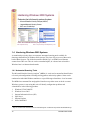
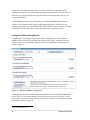
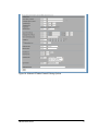
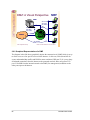
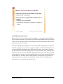
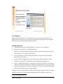
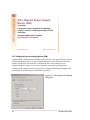
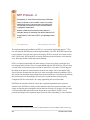
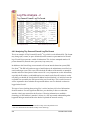
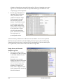
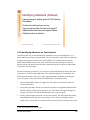
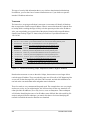
1.4.6 Group Policy and Active Directory
Group Policy is an Active Directory-based mechanism for controlling user and computer
desktop environments in Windows 2000 domains. Settings for such items as security,
software installation, and scripts can be specified through Group Policy. Group Policy is
applied to groups of users and computers based on their location in Active Directory.
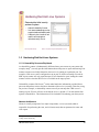
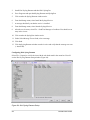
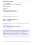
Figure 1: Group Policy Microsoft Management Console (MMC)
Group Policy settings are stored in Group Policy objects (GPOs) on domain controllers.
GPOs are linked to containers—sites, domains, and organizational units (OUs)—within the
Active Directory structure. Because Group Policy is so closely integrated with Active
CMU/SEI-2004-HB-001
19
Directory, it is important to have a basic understanding of Active Directory structure and
security implications prior to implementing Group Policy. Group Policy is an essential tool
for securing Windows 2000. It can be used to apply and maintain a consistent security policy
across a network from a central location [NSA 03c]. As mentioned in the slide on page 19, a
great amount of granularity is provided by Group Policy. Hundreds of environment variables
and policies can all be centrally configured and deployed with the convenience of a very easy
to use interface.
GPOs can be created and/or edited in one of two ways:
1.
In the MMC, load the Group Policy snap-in.
2.
In the Active Directory Users and Computers or Active Directory Sites or Services tools,
specify a new Group Policy for a container.
The latter is the preferred method as it clearly shows and maintains the GPO scope.
Linking a GPO to a site, domain, or OU causes the settings in the GPO to affect computer or
user objects in that container. GPO linking to Active Directory container objects is flexible. A
single GPO can be linked to multiple sites, domains, and OUs. Also, multiple GPOs can be
linked to a single site, domain or OU. When a GPO is created, it is automatically linked to the
container in which it is created. None of the 400-plus settings are initially defined. GPOs
linked to domains and OUs are created using Active Directory Computers and Users. GPOs
linked to sites are created using Active Directory Sites and Services. When deciding to unlink
a GPO from a container, it is recommended that only the link, and not the entire GPO, be
deleted. This allows the GPO to be relinked later in case there is a problem. It is possible to
create an unlinked GPO for a given domain with the Group Policy MMC snap-in and link it
to an Active Directory container object at some future time. To reduce unnecessary
complexity and avoid misconfiguration, it is recommended that GPOs not be linked to sites
as a general rule.
A GPO linked to a domain applies to all users and computers in the domain. By inheritance,
it is also applied to all users and computers in child OUs. Within a domain tree, Group Policy
is not inherited between domains. For example, a GPO in a parent domain will not apply to
its child domains. A GPO linked to an OU is applied to all users and computers in the OU. By
inheritance, the GPO is also applied to all child OUs under the parent OU. By default, only
domain administrators and enterprise administrators have the authority to link GPOs to
domains and OUs, and only enterprise administrators have the authority to link GPOs to sites.
Members of the Group Policy creator owners group can create and modify GPOs for the
domain, but cannot link them.
20
CMU/SEI-2004-HB-001
GPOs are cumulative; the last GPO applied overrides previously applied GPOs. When
multiple GPOs exist within a container’s hierarchy, this is the order in which they are
processed and applied:
•
Local GPO
•
Site GPO
•
Domain GPO
•
Organizational unit GPO
•
Child OU GPO
Group Policies are cumulative, as long as they do not conflict. In other words, if a given
container object links to multiple GPOs, the non-conflicting settings from all of the GPOs
will affect that container. There is one exception to the accumulation rule: when processing IP
Security or User Rights settings, the last GPO processed overwrites any previous GPOs.
When GPOs conflict, the last setting to be processed generally applies. The two clear-cut
cases for this rule are parent/child settings and settings from multiple GPOs linked to the
same container. When settings from different GPOs in the Active Directory parent/child
hierarchy conflict, the GPO settings for the child container apply. When settings from
multiple GPOs linked to the same container conflict, the settings for the GPO highest in the
list apply. Administrators can rearrange this list to raise or lower the priority of any GPO in
the list [NSA 03c].
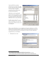
Creating, Configuring, and Linking a New GPO
To make this easier to grasp, let’s create a new GPO, configure it, and link it to an Active
Directory container—in this case, the Engineering Organizational Unit.
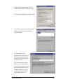
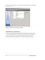
1.
First, we’ll open the Active
Directory Users and Computers
MMC snap-in on our Windows
2000 domain controller.
2.
Then we right click on the
Engineering OU and select
properties.
CMU/SEI-2004-HB-001
21
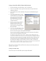
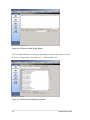
3.
We’ll click the Group Policy tab and
then click the New button and name
the GPO Engineering.
4.
Now we’ll click the Edit button
to configure the settings of this
specific GPO.
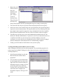
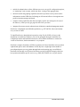
5.
In this case, we’re only going to
make one configuration; we
need to edit the security settings
of the Engineering users’
Internet Explorer browser so a
specific URL is added as a
Trusted Site (for easier
collaboration with other
developers).
6.
In the MMC, we select User Configuration > Windows Settings > Security > and double
click Security Zones and Content Ratings.
7.
We click Import the current
security zones and privacy
settings and then click the
Modify Settings button.
22
CMU/SEI-2004-HB-001
8.
We select Trusted Sites and then click the
Sites button.
9.
Now we’ll add the collaborative
development URL to the list by
clicking Add and then OK.
10. Now we click OK a few times and the GPO is created, configured, and linked to the
Engineering OU.
This new IE setting will be applied when users assigned to the Engineering OU log in to the
domain or through periodic policy refreshes. Group Policy is powerful and really quite easy
to use.
CMU/SEI-2004-HB-001
23
Hardening Windows 2000 Systems - 6
Use Windows 2000’ s Security Configuration Toolset to edit and
apply Security Templates—standardizing system security
• Can be used to make registry settings, configure applications
• Enforce file system security settings, account/password policies
• Can be implemented centrally within a Windows 2000 domain by
using Group Policy Objects (GPOs) or applied to local host systems
Demo: Apply Security Templates
to systems via GPOs
© 2003 Carnegie Mellon University
Module 1: Host System Hardening and Availability Monitoring – slide 13
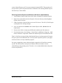
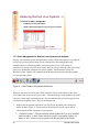
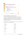
1.4.7 Security Configuration Toolset and Security Templates
Windows 2000 includes support for the Security Configuration Tool Set. The tool set allows
system administrators to consolidate many security-related system settings into a single
configuration file (called a template or inf file because of the file extension “.inf”). It is
possible to layer security configuration files to adjust for different software applications and
security settings. These security settings may then be applied to any number of Windows
2000 machines either as part of a GPO or through local computer configuration.
The Security Configuration Tool Set can be used to analyze and configure the following areas:
•
account policies – includes Password Policy, Account Lockout Policy, and Kerberos Policy
•
local policies – includes Audit Policy, User Rights Assignment, and Security Options
•
event log – includes settings for the event logs
•
restricted groups – includes membership settings for sensitive groups
•
system services – includes configurations for system services such as network transport
•
registry – includes registry key Discretionary Access Control List (DACL) settings (i.e.,
registry key permissions)
•
file system – includes NTFS file and folder DACLs (i.e., file and folder permissions)
In actuality, the Security Configuration Tool Set consists of two MMC snap-ins: Security
Configuration and Analysis and Security Templates.9
9
https://www.microsoft.com/WINDOWS2000/techinfo/howitworks/security/sctoolset.asp
24
CMU/SEI-2004-HB-001
Security Configuration and Analysis
The Security Configuration and Analysis MMC allows administrators to
•
create and/or edit security configuration files
•
perform a security analysis
•
graphically review the analysis results
•
apply a security configuration to a local system
The GUI provides different colors, fonts, and icons to highlight the differences between the
baseline information and the actual system settings. When an analysis or configuration is
performed, all security areas within a security template are included in the analysis.
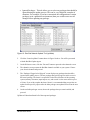
Security Templates
Security templates are files that contain a set of security configurations. Using templates is an
easy way to standardize security across a platform or domain. Templates can be applied to
Windows 2000 computers either by being imported into a GPO or by being directly applied
to the local computer policy. Templates cannot be applied to a system or group of systems
using the Security Templates MMC, which only allows administrators to create, view, and
edit security templates (.inf files). Templates can be imported into GPOs or they can be
applied to local systems using the Security Configuration and Analysis MMC [NSA 03d].
To help you understand this better, let’s view and then edit a security template provided by
the NSA, import it into a GPO, and then apply the template to our User Systems OU.
1.
First, let’s open the Security
Templates MMC and edit the
NSA’s Windows 2000
Professional template file
(NSA w2k_workstation). This
template is one of several that
come with the NSA Guide to
Securing Microsoft Windows
2000 Group Policy: Security
Configuration Tool Set [NSA
03d].
CMU/SEI-2004-HB-001
25
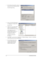
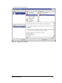
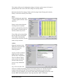
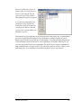
For this example, we’ll disable
the fax service on all user
systems.
2.
When configuring system services
with security templates, you must
configure the Access Control List
(ACL) for each service. When a
service is explicitly disabled, its
ACL should also be secured by
changing the default ACL from
Everyone Full Control to grant
Administrators and SYSTEM Full
Control and Authenticated Users
Read Access.
3.
Click OK on both of the dialogue
boxes and then check your
template’s setting for the fax
service; it should be disabled.
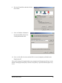
4.
Now we have to save
our changes to the
template. Right click
on the NSA
w2k_workstation
template and then
click Save.
26
CMU/SEI-2004-HB-001
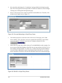
5.
The next step is to import this template into
a Group Policy Object that is Linked to our
User Systems OU. Open the Active
Directory Users and Computers MMC on
your Windows 2000 domain controller and
then right click on the User Systems OU.
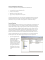
6.
Click Properties and then click on the
Group Policy Tab. Select the User System
GPO (in this case the GPO was already
created).
7.
Now we’ll click the Edit button and then
browse within the Group Policy MMC to
Computer Configuration > Windows
Settings > Security Settings.
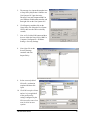
8.
Now right click on the
Security Settings
container and click
Import Policy.
9.
Select our newly edited
NSA w2k_workstation
template and then click
Open.
10. Click OK a couple of times
and we’ve just applied all
of the good security
settings configured by the
NSA (as well as one of our
own) to all of our user
systems.
CMU/SEI-2004-HB-001
27
Hardening Windows 2000 Systems - 7
Harden Internet Information Services (IIS)
• NTFS Permissions on Web Sites
• IIS Lockdown Wizard and URLScan.exe
• IIS Authentication techniques
Demo: IISlockd.exe
© 2003 Carnegie Mellon University
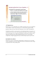
Module 1: Host System Hardening and Availability Monitoring – slide 14
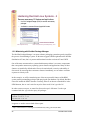
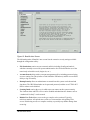
1.4.8 Harden Internet Information Services (IIS)
It’s no secret that IIS has had plenty of bugs in its code—so much so that Gartner, Inc.
recommended that it be entirely replaced in favor of a more secure solution [Bryce 01].
Gartner has been criticized for this, because IIS is so widely implemented and because IIS
can, in fact, be rather secure—if the administrator is vigilant and well informed. Microsoft
has provided truckloads of whitepapers, checklists, and tools for securing IIS. However, the
key is to begin with Windows 2000 Server, because the underlying operating system must be
hardened in conjunction with the specific requirements of the service (in this case IIS).
28
CMU/SEI-2004-HB-001
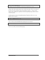
Check the NTFS file and folder
permissions for the location of the Web
site files. Ensure that only the minimum
essential privileges are granted,
especially in the case of IIS systems
accessible from the Internet.
Additionally, consider applying the
Hisecweb.inf security template10 to your
IIS server. It is configured by Microsoft
to position an IIS server (along with the
IISlockd.exe tool) in a very secure state.
The IIS Lockdown Wizard11 is a great
utility for hardening some of the weak
default settings and other security issues
surrounding IIS.
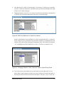
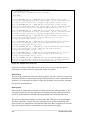
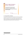
When executed, IISlockd.exe is very straightforward. It starts by checking to see if IIS in
installed on the system and whether or not the Lockdown Wizard has been previously run.
Then it presents the following series of dialog boxes to help you set up the appropriate
configuration for your environment.
1.
10
11
Identify the server’s role.
http://support.microsoft.com/support/misc/kblookup.asp?id=Q316347
This free software may be downloaded from http://www.microsoft.com/downloads/
details.aspx?displaylang=en&FamilyID=DDE9EFC0-BB30-47EB-9A61-FD755D23CDEC.
CMU/SEI-2004-HB-001
29
2.
Select the Internet service(s).
3.
Disable Script maps.
4.
Disable weak default features.
30
CMU/SEI-2004-HB-001
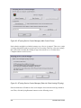
5.
Install URLScan.exe.
6.
Apply the configuration.
CMU/SEI-2004-HB-001
31
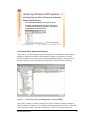
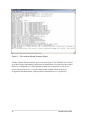
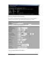
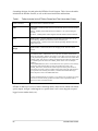
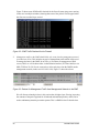
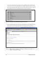
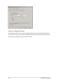
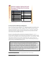
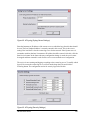
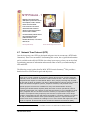
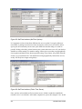
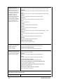
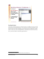
Figure 2: IIS Lockdown Wizard Summary Report
An IIS Lockdown Wizard summary report is shown in Figure 2. The IIS Meta-base is backed
up by the wizard so that running it again allows an administrator to revert back to the original
IIS server’s configuration. For more information about how to harden IIS, see the Secure
Internet Information Services 5 Checklist [Microsoft 03b] and the Guide to the Secure
Configuration and Administration of Microsoft Internet Information Services 5.0 [NSA 03a].
32
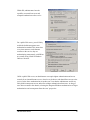
CMU/SEI-2004-HB-001
Within IIS, administrators have the
capability to control how users and
computers authenticate to the service.
For a public Web server, you will likely
enable the default anonymous user
authentication method. This means that
every time someone on the Internet
connects to the service, they are
authenticating anonymously with IIS but
are actually using a built-in Windows
2000 user account.
Unlike a public Web server, an administrator can require tighter authentication and access
controls for an internal Intranet server, where he or she knows who should have access to the
service. In the above authentication screenshot you’ll see that the administrator would very
likely disable anonymous access and utilize stronger authentication from users. As long as
users have accounts in the domain, selecting the Integrated Windows authentication or Digest
authentication can be transparent from the users’ perspective.
CMU/SEI-2004-HB-001
33
The administrator could
harden the service further by
only allowing connection
requests from Internal IP
addresses. In this case, only
source addresses from the
RFC 191812 private address
space 10.0.0.0 network will
be allowed to make a
connection. (Although this
contributes to the defense in
depth goal, it might be done more effectively by a host-based firewall.)
IIS also has the capability to use industrial strength SSL encryption via PKI certificates. IIS
can import certificates from trusted CA’s (like Verisign) or from an internal certificate server.
In the case of the later, it can be configured to authenticate user digital certificates, thereby
increasing the reliability of the authentication considerably.
12
http://www.isi.edu/in-notes/rfc1918.txt
34
CMU/SEI-2004-HB-001
Hardening Windows 2000 Systems - 8
Use a host-based firewall to control network access
Many products available, but we’re using Tiny
Personal Firewall 2.015 (freeware)
• Lightweight, nice user interface, granular configuration of
rules, MD5’ s applications
• Create rules for accepted traffic then create one Deny All rule
and log for matches against this rule
© 2003 Carnegie Mellon University
Module 1: Host System Hardening and Availability Monitoring – slide 15
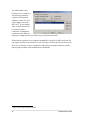
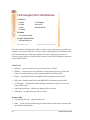
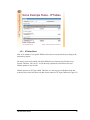
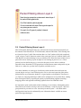
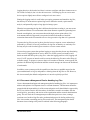
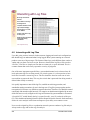
1.4.9 Host-Based Firewalls
Host-based firewalls are one of the best (and cheapest) ways to significantly harden your host
systems. Tiny Personal Firewall (TPF) Version 2.01513 has been around for a couple of years
and has been scrutinized carefully for security issues. We still find it to be the best free
Windows personal firewall out there—mainly because of the granularity it provides regarding
rules and features like syslog capability, hashing of registered applications, and its intuitive
interface. In fact, we like it better than any of the commercial firewalls we’ve tried.
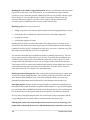
Setting up Tiny Personal Firewall
Installing TPF 2.015 is easy and upon the required reboot it will start prompting you to build
your rules via pop-up windows. It is very lightweight and doesn’t affect performance
noticeably even on busy Windows servers.
13
This free software may be downloaded at http://download.com.com/3302-2092_4-6313778.html?pn=1&fb=2.
CMU/SEI-2004-HB-001
35
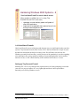
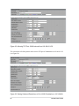
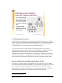
A good strategy with this tool is
to keep the default “Ask me
First” setting so you can choose
to allow traffic on a case by
case basis when prompted. You
can also click a check box and
permanently create a rule in
your firewall table so you won’t
be prompted in the future.
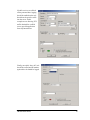
You have the ability
to customize this rule
by service ports and
IP addresses.
36
CMU/SEI-2004-HB-001
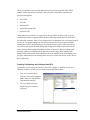
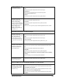
If public services are offered
on the protected host, logging
should be enabled on the rule
that allows the specific traffic
into the server. In this
example we are allowing TCP
traffic destined for our Web
server (port 80) application
from any Internet host.
Finally, an explicit “deny all” rule
should be created and all matches
against this rule should be logged.
CMU/SEI-2004-HB-001
37
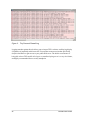
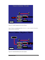
Figure 3: Tiny Personal Firewall Log
Logging matches against this rule allows you to inspect TPF’s real-time scrolling log display
for patterns of potentially malicious traffic. You can then create new rules that specifically
deny this bad traffic to gain access to your public Web server. The built-in convenience of
being able to have TPF send all of its logs to a centralized syslog server is a very nice feature,
and highly recommended from a security standpoint.
38
CMU/SEI-2004-HB-001
Hardening Red Hat Linux Systems
Determine the initial security
posture of system
• Nessus Vulnerability Scanner
• Run nessus-update-plugins script
to get the latest vulnerability tests
• Enable only the Linux/Unix and
specific service plugins to
optimize accuracy of scan
© 2003 Carnegie Mellon University
Module 1: Host System Hardening and Availability Monitoring – slide 16
1.5 Hardening Red Hat Linux Systems
1.5.1 Vulnerability Scanners Explained
A vulnerability scanner is fundamentally different from a port scanner. A port scanner (for
example, nmap14) can only provide information about what ports are open and listening. Port
scanners cannot even reliably determine what service is running on a particular port. For
example, a Web server can be configured to run on port 22 which is normally reserved for
SSH. A port scanner will only report that port 22 was found to be open, leading the casual
scanner to believe that the SSH service is available on the target system.
Vulnerability scanners like Nessus,15 on the other hand, take information provided from a
port scan and perform various checks to determine what service is running. Therefore, using
our previous example, a vulnerability scanner can tell you not only that a Web server is
running on port 22 but it will also reveal that the server is Apache 1.3.26 and contains four
separate vulnerabilities. This information will be invaluable in hardening your host system.
Nessus Architecture
Nessus is actually comprised of two major components; a server (nessusd) which is
responsible for performing the scan, and a client (nessus) that can parameterize scans and
view reports.
14
15
http://www.insecure.org/nmap/
http://www.nessus.org
CMU/SEI-2004-HB-001
39
•
Nessusd: The server component of Nessus that listens for client connections on TCP port
1241. All client sessions are authenticated using an SSL-like method. While the Nessus
client has been ported to many different operating systems, this portion must be installed
on a Linux/UNIX system.
•
Nessus: The Nessus client is the component that scanners use to configure the
parameters of Nessus scans. Once the scan has finished, results will also be viewed
through the client interface.
Installing and Running Nessus
Nessus installation is an extremely simple process. With the release of Nessus 2.0, the
installation process has been automated through the use of the Nessus-installer shell script.
To install Nessus:
1.
Download nessus-installer.sh from any of the available mirror sites.
2.
Open a shell as root, and enter the following command:
% sh nessus-installer.sh
This script will handle downloading Nessus packages, compiling (if necessary), and
placing files in the proper directories.
40
CMU/SEI-2004-HB-001
Configuring Nessus:
First, create a user account.
Figure 4: Adding a User in Nessus
1.
At the shell prompt, enter the following command:
% nessus-adduser
2.
Enter a user name.
CMU/SEI-2004-HB-001
41
3.
Enter “pass” as the Authentication method. This will tell Nessus to use a password (as
opposed to a certificate).
4.
Enter a password.
5.
Leave the rules section blank. If you wanted to limit a user’s scanning ability, you could
enter appropriate rules in this section.
6.
Update the Nessus plug-ins to get the latest vulnerability tests.
% nessus-update-plugins
7.
Start the nessusd server with the following command:
% nessusd -D
Next, create an SSL certificate.
1.
At the shell prompt, enter the following command:
% nessus-mkcert
2.
Enter the information that it asks for. This certificate will be presented to all Nessus
clients that connect to this server.
3.
Press enter to accept the certificate.
Figure 5: Adding an SSL Certificate
42
CMU/SEI-2004-HB-001
Next, configure Nessus Client.
1.
At the shell prompt, enter the following command:
% nessus
Figure 6: Nessus Intro Screen
2.
Before starting a scan, all users must log into the Nessus client.
3.
Configure the following scan parameters:
Plug-ins
From this tab, users can select which vulnerability tests will be run on the target host.
Since we will be scanning a Linux machine as our target, we should disable all Plugins
that are not Linux specific. Minimally, we should remove the Windows, Windows User
Management, CISCO, Firewalls, and NetWare plug-ins.
CMU/SEI-2004-HB-001
43
Also, it is probably a good idea to disable the Denial of Service plug-in because we
would rather not cause our target host to crash.
Prefs
Allows you to supply extra information to some of the security checks. For instance, you
can provide Nessus with specific directories to look for during its FTP and HTTP
attacks. Also, you can configure NIDS evasion techniques.
Scan Options
Provides the ability to change certain scan options. You can choose the port scanner to
use, how many hosts should be scanned simultaneously and the number of plug-ins to
run at the same time.
Target Selection
Specifies the host to be scanned. You can enter a new host, a new network, or you can
restore a previously saved session.
User
Allows the user to enter rules that further restrict the scanning ability. For example, if
you are scanning a network and there are a small number of hosts you would prefer to
ignore, you can enter those hosts in this tab as opposed to dissecting the network into
blocks that exclude those hosts.
KB
Using the knowledge base allows for users to perform differential scans. Using the KB
tab allows the user to test only unseen hosts (increases speed), or to only report when the
security posture of a machine has changed from a previous scan.
4.
Click on Start the Scan to begin.
Figure 7: Nessus Scan Progress Indicator
44
CMU/SEI-2004-HB-001
5.
Review the results of the scan.
Figure 8: Nessus Scan Results
CMU/SEI-2004-HB-001
45
Hardening Red Hat Linux Systems - 2
Remove unnecessary OS features and applications
• Use RH Package Manager (RPM) to remove unnecessary
packages
• Available in command line and graphical formats
Demo: Minimize with RPM
© 2003 Carnegie Mellon University
Module 1: Host System Hardening and Availability Monitoring – slide 17
1.5.2 Minimizing with Red Hat Package Manager
The Red Hat Package Manager is an open software packaging system that greatly simplifies
the process of maintaining a system. As the name suggests, RPM originated on the Red Hat
distribution of Linux, but it is present and functional on other versions of Linux/UNIX.
One of the most common tasks a system administrator performs is to remove components
that correspond to unnecessary operating system features and applications. Many of these
features are installed by default and will never be noticed until a security vulnerability is
discovered. By removing these extraneous features immediately, we can reduce our future
exposure to security risks.
In this example, we will be introducing two of the most powerful features of the RPM
system; namely uninstalling packages and querying the rpm database. By default, Red Hat
Linux 8.0 installs the ISDN16 daemon. Currently, there are no known vulnerabilities in the
ISDN daemon, but we won’t wait for any to be discovered. So let’s get rid of it!
In order to remove an rpm, we must first discover the rpm’s full name. Use the rpm
command with the –qa switch to query all packages:
% rpm –qa | grep isdn
isdn4k-utils-3.1-58
xisdnload-1.38-58
It appears we need to remove both of these rpms.
16
http://searchwebservices.techtarget.com/sDefinition/0,,sid26_gci212399,00.html
46
CMU/SEI-2004-HB-001
% rpm –e isdn4k-utils-3.1-58
error: Failed dependencies
isdn4k-utils is needed by (installed) xisdnload-1.38-58
It appears that another package depends on the isdn4k-utils package. We have two options at
this point. One option would be to ignore this dependency using the --nodeps switch.
However, that is probably not a good idea because the dependent package cannot be trusted
to function properly.
Our other option is to remove the dependent package. Fortunately, in this case, we were
going to remove it anyway.
% rpm –e xisdnload-1.38-58
% rpm –e isdn4k-utils-3.1-58
Now, let’s make sure that the ISDN daemon packages have been removed.
% rpm –qa | grep isdn
%
We have successfully removed the ISDN packages.
CMU/SEI-2004-HB-001
47
Hardening Red Hat Linux Systems - 3
Solutions for patch management
• up2date tool via Red Hat Network
• Update individual packages from sources (rpms or tarballs)
Demo: up2date
© 2003 Carnegie Mellon University
Module 1: Host System Hardening and Availability Monitoring – slide 18
1.5.3 Patch Management for Red Hat Linux Systems with Up2date
Keeping your operating system and applications current with the latest patches is possibly the
easiest way to protect yourself from security vulnerabilities. Even though Microsoft
dominates the news concerning patches and security holes, Linux is not without its
deficiencies in certain areas. In order to ensure that your system is running at the most current
patch level, RedHat has included a tool called “up2date” which functions exactly like
Windows Update. Up2date will contact the Red Hat Network and retrieve the latest updates
for your operating system.
Figure 9: Linux Taskbar with up2date Notification
When you first boot into Linux after a fresh install, the task bar at the bottom of the screen
will resemble the one shown in Figure 9 above. The interesting part of the taskbar is the small
red circle with the white exclamation point. This icon indicates that your system may need to
download critical updates. Here’s how you should proceed:
1.
Double click the up2date notification icon. You will be presented with a dialog box
similar to that in Figure 10. The two tabs in this dialog box provide a great deal of
information about the current state of your system:
•
48
Available Updates – This tab indicates which updates have yet to be installed
on this machine. A fresh Linux install can require a great many updates (as
many as 200), whereas current systems will only need the latest patches.
CMU/SEI-2004-HB-001
•
Ignored Packages – This tab allows you to select any packages that should be
ignored during the update process. This can be very helpful in a number of
situations. For example, if you have customized the configuration of certain
packages (as in a production environment) then you would want to test all
changes before updating any package.
Figure 10: Red Hat Network Update Tool (up2date)
2.
Click the “Launch up2date” button shown in Figure 10 above. You will be presented
with the Red Hat Update Agent.
3.
On the Welcome screen, click the “Forward” button to proceed to the channels screen.
4.
The channels screen presents the Red Hat channels available to your system. Choose
your favorite channel and proceed.
5.
The “Packages Flagged to be Skipped” screen displays any packages that should be
ignored in the update process. The one package that typically appears in this screen is
the kernel package. The kernel is responsible for the basic functions of the operating
system (memory allocation, input/output, etc), and as such it is the most sensitive piece
of Linux. If you wish to update the kernel, then it is recommended that you perform an
update for that specific purpose after the other packages are updated. Proceed to the next
screen.
6.
On the available packages screen, choose the packages that you want installed, and
proceed.
Up2date will download/install all of the requested packages.
CMU/SEI-2004-HB-001
49
Hardening Red Hat Linux Systems - 4
Securing Red Hat Linux Services
• Use chkconfig—list to see what services are running
• Remove services from /etc/init.d directory to stop them
from loading upon boot-up
• Remove all services not explicitly required to function (i.e.
xinetd services, etc.)
Demo: Removing xinetd
© 2003 Carnegie Mellon University
Module 1: Host System Hardening and Availability Monitoring – slide 19
1.5.4 Securing Red Hat Linux Services
As you watch Linux boot up, you might notice that the operating system starts a great deal of
services initially. What you might not realize is that, like Windows, many of these services
are unnecessary and can be safely stopped or removed. Great! How do you find out what is
running and how do you stop a service? Linux makes this whole process very
straightforward.
Run Levels
First, before we can disable a service, we need a little background on run levels. Run levels
represent all of the modes in which a Linux system can boot. Though this varies from UNIX
to UNIX (Linux, AIX, HP-UX, etc) they are very similar. These are the run levels for Linux
(excerpted from /etc/inittab):
0: Halt (Stops the OS and sometimes powers down the system)
1: Single user (Doesn’t start network, no password for root. Needed for debugging)
2: Multi-user (Starts the whole OS, but does not mount remote file systems)
3: Full multi-user (Starts the whole OS and remote file systems, also called text mode)
4: Unused
5: X-windows (Boots system directly into X-windows GUI)
6: Reboot (reboots machine)
50
CMU/SEI-2004-HB-001
On a Linux machine, all information about services is stored in the /etc/rc.d directory
(see Figure 11).
% ls /etc/rc.d
init.d
rc0.d
rc
rc1.d
rc2.d
rc3.d
rc4.d
rc5.d
rc6.d
rc.local
rc.sysinit
Figure 11: Contents of rc.d Directory
There are two interesting points concerning this output. The first item of note is that the
init.d directory contains the startup scripts for every service that might be started by the
system (see Figure 12).
% ls /etc/rc.d/init.d
anacron
gpm
apmd
halt
atd
iptables
autofs
irda
crond
isdn
firstboot kdcrotate
functions keytable
killall
kudzu
lpd
netfs
network
nfs
nfslock
nscd
ntpd
pcmciasingle
portmap
random
rawdevices
rhnsd
saslauthd
sendmail
ypbind
snmpd
snmptrapd
sshd
syslog
xfs
xinetd
Figure 12: Contents of init.d Directory
The second item is that a directory exists for each run level. Run level 0 corresponds to
rc0.d, run level 1 corresponds to rc1.d, and so on. These rc[0-6].d directories
control which services are loaded in each run level. Since this machine is booted into Xwindows, we are in run level 5, and thus all the files in the /etc/rc.d/rc5.d directory
were executed when this machine booted up. The contents of the rc5.d directory are
displayed in Figure 13:
% ls /etc/rc.d/rc5.d
K05saslauthd
S14nfslock
K20nfs
S05kudzu
K24irda
S08iptables
K50snmpd
S09isdn
K50snmptrapd
S10network
K47nscd
S12syslog
K47ntpd
S13portmap
K95firstboot
S56rawdevices
S55sshd
S17keytable
S20random
S24pcmcia
S25netfs
S26apmd
S28autofs
S56inetd
S60lpd
S80sendmail
S85gpm
S90crond
S90xfs
S95anacron
S95atd
S99local
Figure 13: Contents of rc5.d Directory
In the output above, each file has an “S” or a “K” before it, followed by a number and then
the service name. The files that start with “K” are killed (not started) on this run level
whereas those beginning with an “S” are started in order from lowest number to highest
number. In this example, S10network will start before S56inetd (network services).
CMU/SEI-2004-HB-001
51
Note: More about the Linux boot process is available in Chapter 3 of The Official Red Hat
Linux Reference Guide [Red Hat 03].
Now that we know how the system starts its services, we can check to see which ones are
running by using the chkconfig command. The chkconfig command shown in Figure
14 will query all services and return an alphabetized list displaying only the services that are
listed as “on.”
% chkconfig
anacron
apmd
atd
autofs
crond
gpm
iptables
isdn
keytable
kudzu
lpd
netfs
network
nfslock
pcmcia
portmap
random
rawdevices
rhnsd
sendmail
sshd
syslog
xfs
xinetd
–-list | grep on | sort
0:off
1:off
2:on
0:off
1:off
2:on
0:off
1:off
2:off
0:off
1:off
2:off
0:off
1:off
2:on
0:off
1:off
2:on
0:off
1:off
2:on
0:off
1:off
2:on
0:off
1:on
2:on
0:off
1:off
2:off
0:off
1:off
2:on
0:off
1:off
2:off
0:off
1:off
2:on
0:off
1:off
2:off
0:off
1:off
2:on
0:off
1:off
2:off
0:off
1:off
2:on
0:off
1:off
2:off
0:off
1:off
2:off
0:off
1:off
2:on
0:off
1:off
2:on
0:off
1:off
2:on
0:off
1:off
2:on
0:off
1:off
2:off
3:on
3:on
3:on
3:on
3:on
3:on
3:on
3:on
3:on
3:on
3:on
3:on
3:on
3:on
3:on
3:on
3:on
3:on
3:on
3:on
3:on
3:on
3:on
3:on
4:on
4:on
4:on
4:on
4:on
4:on
4:on
4:on
4:on
4:on
4:on
4:on
4:on
4:on
4:on
4:on
4:on
4:on
4:on
4:on
4:on
4:on
4:on
4:on
5:on
5:on
5:on
5:on
5:on
5:on
5:on
5:on
5:on
5:on
5:on
5:on
5:on
5:on
5:on
5:on
5:on
5:on
5:on
5:on
5:on
5:on
5:on
5:on
6:off
6:off
6:off
6:off
6:off
6:off
6:off
6:off
6:off
6:off
6:off
6:off
6:off
6:off
6:off
6:off
6:off
6:off
6:off
6:off
6:off
6:off
6:off
6:off
Figure 14: Output from chkconfig
The example system has been started in run level 5 (X-windows), so a quick glance at
column 5 will show all the services that are currently running. Note also that these are all the
files that began with an “S” in the /etc/rc.d/rc5.d directory.
Now, since this machine is not a mail server, there is no reason for us to be running
sendmail.17 Given sendmail’s particularly checkered past (some consider it to be the buggiest
daemon ever written); there is reason to be seriously concerned. So let’s remove it!
17
http://www.sendmail.org
52
CMU/SEI-2004-HB-001
Stopping a Service
There are two steps that must be executed to stop a service. First you must terminate the
currently running service, and then you must prevent it from starting in the future.
1.
Stop the service.
% service sendmail stop
2.
Prevent the service from starting in the future.
Remove the service. The following command will remove any references to the sendmail
service from all run levels (use this command only if you are really sure that you won’t
need to use a particular service):
% chkconfig –-del sendmail
By running chkconfig --list again, you can see that the sendmail service is no
longer listed.
Alter the run level properties of the service. Instead of removing the service entirely, you
can simply turn off the service in specific run levels. The following command will mark
sendmail as “off” in run levels 3 and 5. Note: you should never turn a service “on” in
run levels 0 or 6 (system shutdown and reboot, respectively).
% chkconfig --level 35 sendmail off
% chkconfig --list sendmail
sendmail
0:off
1:off
2:on
CMU/SEI-2004-HB-001
3:off
4:on
5:off
6:off
53
Hardening Red Hat Linux Systems - 5
Use Bastille tool to automatically harden system
• Edits ACLs, config files, security settings on Unix systems
• Instructional graphical interface with in-depth explanations
• Can quickly revert/undo changes made that may have
caused problems—test on non-production systems first!
Demo: Bastille
© 2003 Carnegie Mellon University
Module 1: Host System Hardening and Availability Monitoring – slide 20
1.5.5 Bastille-Linux
Bastille-Linux is a user-configurable series of PERL scripts that can be run on an installation
of Linux/UNIX to “harden” the operating system. Currently, Bastille supports RedHat,
Mandrake, Debian, SuSe, and TurboLinux distributions as well as HP-UX and MacOS X.
The Bastille scripts allow a system operator to easily implement industry “best practices” to
dramatically increase the security of the operating system. Bastille was developed according
to the recommended security configurations published by CERT, SANS, and other security
authorities. In particular, the scripts can disable unnecessary services, secure default
configurations, configure logging, and set up a firewall based upon specific system needs.
How Bastille-Linux Works
Bastille-Linux works by systematically working through a comprehensive list of potential
security vulnerabilities. At each step, Bastille asks the user to customize the security settings
for a particular facet of the operating system.
54
CMU/SEI-2004-HB-001
Figure 15: Bastille Intro Screen
The left-hand portion of Bastille’s intro screen lists the extensive security settings available
through the configuration utility:
•
File Permissions restricts access to network utilities including ifconfig and runlevel
which are normally reserved for system administration. It will also disable the use of the
notoriously vulnerable r-tools (rlogin, rsh, etc.).
•
Account Security helps enforce account management policies including password aging,
access to setting cron jobs (similar to Task Scheduler in Windows), and the root account’s
ability to log in remotely.
•
Bootup Security allows an administrator to control how this system can be booted and
shut down. The GRUB bootloader can be password protected, and the use of CTRL-ALTDEL to reboot can be disabled.
•
Securing Inetd restricts the ways in which users can connect to this system remotely.
The cleartext telnet and FTP services can be disabled and administrative banners such as
“Authorized Use Only” can be created.
•
Disable User Tools allows access to the gcc compiler to be restricted. Typically,
malicious attackers will upload source code to a victim machine after gaining illicit
access. Disallowing access to a compiler can delay or possibly stop further damage from
occurring.
CMU/SEI-2004-HB-001
55
•
Configuring PAM sets restrictions on usage of system resources. Console access (which
typically includes special system-level access rights) can be restricted to certain users.
Configuring PAM also allows you to set limits on the number of processes users can
own. Limiting processes is useful because it will prevent a single user from executing a
denial of service attack by forking enough processes to starve legitimate programs.
•
Logging configures the syslog service, allowing an administrator to specify which events
should be logged and then port these logs to a centralized syslog server.
•
Misc. Daemons disables system daemons which are often unneeded given the
configuration of the system and the information provided to Bastille thus far.
•
TMPDIR configures user accounts to avoid using /tmp for storage of temporary files.
Security issues arise when the /tmp directory is abused on a multi-user system
•
Firewall creates an IPtables-based firewall. A very comprehensive list of questions
follow which allow the firewall to be customized with respect to features including
services to be allowed/rejected, services to audit, default policies, and others.
•
PSAD, which stands for Port Scan Attack Detector, can be configured to run at varying
intervals with customizable parameters such as time between scans, number of suspicious
packets seen, use of Snort signatures, etc. (This setting is only available if the firewall is
configured as well.)
Depending on the configuration of the host system, several other categories may also appear.
These categories include sendmail, DNS, Apache, printing, and FTP.
Once all of the questions have been answered, Bastille performs a validity check on your
answers and then customizes its scripts to apply the changes it can do automatically. After
performing the actions it can do automatically, the tool produces a “to do” list
(/var/log/Bastille/TODO) that describes remaining changes that the user must
perform manually. This list includes reboots as changes may require.
Running Bastille-Linux
Bastille-Linux supports two methods of configuration: interactive and non-interactive. First
time users must use interactive mode to create a configuration profile.
•
Interactive Use: The user interface guides the user through a series of questions. Each
step contains a description of the security decision being suggested as well as the
cost/benefit of the decision
•
Non-Interactive Use: Useful for duplicating a security configuration across multiple
machines that have the same operating system and applications installed.
56
CMU/SEI-2004-HB-001
Much of the power of Bastille-Linux is derived from its interactive setup routine. It is for this
reason that we suggest use of this mode.
Bastille itself can be run with the simple steps shown below:
1.
Consult the Bastille-Linux Web site18 to download and install the appropriate modules.
2.
Become root and start Bastille using the following command:
% bastille
3.
Answer the questions Bastille poses.
4.
Save your configuration file.
5.
Apply the changes.
18
http://www.bastille-linux.org/
CMU/SEI-2004-HB-001
57
Hardening Red Hat Linux Systems - 6
Use IPtables Firewall to configure network access
controls
• Easy configuration of rules with Webmin utility
• Set default policy to reject, then configure permit rules for
approved traffic—configure logging for rejected packets
© 2003 Carnegie Mellon University
Module 1: Host System Hardening and Availability Monitoring – slide 21
1.5.6 IPtables Firewall
Linux has many built-in capabilities that allow developers and system administrators to
customize the behavior of the operating system without requiring expensive third party tools.
One such capability that has been available since the 2.4 kernel is IPtables, which is a hostbased firewall configuration system.
At its core, the IPtables system behaves as a stateful packet filter. (For more on stateful
packet filtering, see section 2.4.1, Stateless and Stateful Packet Filtering, on page 74.) Based
on the specific role of the system (e.g., router, workstation), administrators craft rules that
govern how the IPtables systems treats the traffic that passes over the network.
How IPtables Works
In order to understand how IPtables works, you must understand how packets traverse the
IPtables chains. Figure 16 represents the portion of the IPtables packet filter that is relevant
for host based firewalls. In this diagram, the three rectangles (INPUT, FORWARD, and
OUTPUT) represent the three chains that will be used to create our firewall.
58
CMU/SEI-2004-HB-001
Packet destined for
remote machine
Routing
Decision
FORWARD
To network
Packet destined for
local machine
OUTPUT
INPUT
Pass to local
process
Local machine
generates traffic
Local Machine
Figure 16: Host-Based IPtables Chains
The following steps are excerpted from Linux iptables How To [LinuxGuruz 03]:
:KHQDSDFNHWDUULYHVWKHV\VWHPZLOOLQVSHFWWKHSDFNHWKHDGHUWRGLVFRYHUWKH
GHVWLQDWLRQ
,IWKHSDFNHWLVGHVWLQHGIRUWKHORFDOPDFKLQHLWLVSDVVHGGRZQWRWKH,1387
FKDLQ,ILWSDVVHVWKHFKDLQLHWKHUHDUHQRUXOHVWKDWLQGLFDWHWKHSDFNHW
VKRXOGEHGURSSHGWKHQDQ\SURFHVVHVZDLWLQJIRUWKDWSDFNHWZLOOUHFHLYHLW
,IWKHSDFNHWLVGHVWLQHGIRUDUHPRWHPDFKLQHDQGHLWKHURIWKHIROORZLQJ
FRQGLWLRQVH[LVWWKHQWKHSDFNHWLVGURSSHG
• 7KHV\VWHPKDVIRUZDUGLQJGLVDEOHG
• 7KHV\VWHPGRHVQRWNQRZKRZWRURXWHWKHSDFNHW
,IIRUZDUGLQJLVHQDEOHGDQGWKHSDFNHWLVGHVWLQHGIRUDQRWKHUQHWZRUNWKHQ
WKHSDFNHWWUDYHUVHVWKH)25:$5'FKDLQ,IWKHSDFNHWSDVVHVWKLVFKDLQLWZLOO
EHVHQWRXW
)LQDOO\DSURJUDPUXQQLQJRQWKHORFDOPDFKLQHFDQJHQHUDWHQHWZRUNWUDIILF
7KHVHSDFNHWVZLOOWUDYHUVHWKH287387FKDLQ,IWKHSDFNHWSDVVHVWKLVFKDLQLW
ZLOOEHVHQWRXW
When packets are inspected while traversing the chains, the system will apply user-specified
rules in the order they were entered. Therefore, as soon as a packet matches a particular rule,
it will “jump” to the rule’s target (e.g., ACCEPT, REJECT, DROP, etc.) and exit the chain. If
CMU/SEI-2004-HB-001
59
a packet does not match any of the rules, it is said to “fall off” the chain and it will be
handled by the default policy of the chain. In keeping with best practices, we will have our
firewall set up to deny all traffic not explicitly allowed, and so the default policy for our
chains will be DROP.
As you might have noticed, we will not make use of the FORWARD chain because our
machine is a workstation and will not be performing routing tasks. The chains we are
primarily concerned with are the INPUT and OUTPUT chains. These two chains will allow
us to explicitly define what traffic is allowed into and out of a particular system.
Configuring IPtables Using Webmin
Using Webmin19 to configure an iptables firewall is surprisingly easy. On the opening
Webmin screen, select the Networking icon at the top of the screen, and then click on the
Linux Firewall icon. You should be presented with a screen that looks much like the one
shown in Figure 17.
Figure 17: Webmin IPtables Configuration
On this screen you can see the three chains mentioned before, namely INPUT, FORWARD
and OUTPUT, as well as their default policies. In this case, all are set to ACCEPT. At this
point, we have no rules configured for any of the chains. Initially our host machine generates
the nmap run shown in Figure 18.
19
http://www.webmin.com
60
CMU/SEI-2004-HB-001
Figure 18: The Nmap Run Before Firewalling
Let’s say that we want this system to allow only Webmin traffic. We do this by adding the
appropriate rules to the INPUT chain, and then setting the default policy to DROP.
Figure 19: Adding IPtables Rule with Webmin
CMU/SEI-2004-HB-001
61
We set the “Action to take” to ACCEPT and then specify the conditions. Here, we will allow
the packet if it is destined for 10.0.2.170 (the address of the host system), the TCP protocol is
used, and the destination port is 10000.
The last step we must take is to set the default policy for the INPUT chain to DROP.
Setting this feature means that any packets that “fall off” the INPUT chain will be dropped
by the firewall.
Figure 20: Setting the Default Policy for the INPUT Chain
After changing the default policy, our system generates the nmap run shown in Figure 21.
Figure 21: The nmap Run After Firewalling
62
CMU/SEI-2004-HB-001
System Availability
Monitoring Tools
Nagios
• Open source project
• Very mature and extensible
• Complex installation and
configuration
Demarc PureSecure
• Freeware for home use
• Very easy to configure
initial monitoring of
services
© 2003 Carnegie Mellon University
Demo: PureSecure Monitoring Utility
Module 1: Host System Hardening and Availability Monitoring – slide 22
1.6 System Availability Monitoring Tools
The Nagios20 system is an application that monitors hosts, services, and networks. This task
is accomplished by intermittently querying each user-configured service and reporting the
results back to a central correlation engine. Once the low-level setup has been accomplished,
system and network status can be viewed through the use of a Web interface hosted on the
Nagios machine itself (see Figure 22).
Demarc’s PureSecure21 product is actually marketed as an intrusion detection system (a
freeware version is available). However, one of its many features is the capability to do
remote service availability monitoring. PureSecure is quite easy to configure for initial
monitoring of networked services, with all configuration done from within its clean GUI.Pure
20
21
http://www.nagios.org/
http://www.demarc.com/
CMU/SEI-2004-HB-001
63
Figure 22: Nagios Web Interface
1.6.1 Nagios
Nagios includes the following features:22
•
monitoring of network services (SMTP, POP3, HTTP, NNTP, PING, etc.)
•
monitoring of host resources (processor load, disk and memory usage, running processes,
log files, etc.)
•
monitoring of environmental factors such as temperature
•
simple plug-in design that allows users to easily develop their own host and service checks
•
ability to define network host hierarchy, allowing the detection of and distinction
between hosts that are down and hosts that are unreachable
•
contact notifications when service or host problems occur and get resolved (via email,
pager, or other user-defined method)
•
optional escalation of host and service notifications to different contact groups
•
ability to define event handlers to be run during service or host events for proactive
problem resolution
22
http://www.nagios.org/about.php
64
CMU/SEI-2004-HB-001
•
support for implementing redundant and distributed monitoring servers
•
external command interface that allows on-the-fly modifications to be made to the
monitoring and notification behavior through the use of event handlers, the Web
interface, and third-party applications
•
retention of host and service status across program restarts
•
scheduled downtime for suppressing host and service notifications during periods of
planned outages
•
ability to acknowledge problems via the Web interface
•
Web interface for viewing current network status, notification and problem history, log file, etc.
•
simple authorization scheme that allows you to restrict what users can see and do from
the Web interface
1.6.2 How Nagios Works
Nagios itself is merely the aggregation portion of the entire system. In order to actually perform
the checks for services, hosts, etc., Nagios relies on plug-ins.23 The general behavior of Nagios
plug-ins is analogous to that of the plug-ins you’ve come across for other software—they
extend or implement functionality that is unavailable in the core program.
3OXJLQ
1DJLRV3URFHVV
&RUH/RJLF
/RFDO
5HVRXUFHRU
6HUYLFH
3OXJLQ
Local Host
5HPRWH
5HVRXUFHRU
6HUYLFH
Remote Host
Figure 23: Nagios Plug-in Architecture
Nagios plug-ins are completely configurable in their interactions with remote processes and hosts.
Also, an organization running a proprietary network service or protocol can develop its own plugin and incorporate that into the Nagios system. Thus, there is no need to completely overhaul a
Nagios installation when a new type of service or host is incorporated into the network.
23
http://nagios.sourceforge.net/docs/1_0/plugintheory.html
CMU/SEI-2004-HB-001
65
Summary
Host system hardening best practices
Windows 2000 hardening techniques
Red Hat Linux hardening techniques
System monitoring tools
© 2003 Carnegie Mellon University
Module 1: Host System Hardening and Availability Monitoring – slide 23
1.7 Summary
66
CMU/SEI-2004-HB-001
Review Questions
?
1. Name and describe 3 host system hardening
concepts.
2. What tools can help harden a Windows IIS
Web Server?
3. How can Group Policy help secure a Windows
2000 domain?
4. What directory should be inspected to see which
services are loaded on a Red Hat Linux system?
5. What practice should be followed when
administering rules on a host-based firewall?
© 2003 Carnegie Mellon University
Module 1: Host System Hardening and Availability Monitoring – slide 24
1.8 Review Questions
1.
Name and describe three host system hardening concepts.
2.
What tools can help harden a Windows IIS Web Server?
3.
How can Group Policy help secure a Windows 2000 domain?
4.
What directory should be inspected to see which services are loaded on a Red Hat
Linux system?
5.
What practice should be followed when administering rules on a host-based
firewall?
CMU/SEI-2004-HB-001
67
68
CMU/SEI-2004-HB-001
2 Firewalls and Network Access Controls
Advanced Information Assurance
Module 2:
Firewalls and Network Access Controls
CERT® Education and Training
Software Engineering Institute
Carnegie Mellon University
Pittsburgh, PA 15213-3890
© 2003 Carnegie Mellon University
® CERT, CERT Coordination Center and Carnegie Mellon are registered in the
U.S. Patent and Trademark Office by Carnegie Mellon University
The term “firewall” is taken from the structural analog that slows the spread of fire in a
building. In computer literature, the popular press, and vendor marketing materials, the term
is used in many ways. Some people use it to identify a specific hardware component or
software package, while others consider the entire collection of systems and software
deployed as a control mechanism between two networks to be parts of a firewall.
A firewall is a combination of hardware and software used to implement a security policy
governing the network traffic between two or more networks, some of which may be under
your administrative control (e.g., your organization’s networks) and some of which may be
out of your control (e.g., the Internet). A network firewall commonly serves as a primary line
of defense against external threats to your organization's computer systems, networks, and
critical information. Firewalls can also be used to partition your organization’s internal
networks, reducing your risk from insider attacks.
The term firewall has become a broad “catch-all” for systems or software that control access
and packet flow between one system or network and another system or network. These
systems can be appliances, built specifically for filtering the network traffic that passes
through it. They can be routers configured to accept certain types of packets and to discard
others. They can be software components designed to control access to a specific host. They
can be a combination of any of the examples or any other type of system which controls
access and filters unwanted network traffic.
CMU/SEI-2004-HB-001
69
Instructional Objectives
Identify systems and technologies which support
access control enforcement on systems and networks
Implement a network packet filter (layers 3 and 4)
Describe the implementation of a demilitarized
zone (DMZ)
Implement an application proxy which filters
unwanted network traffic
Describe application layer filtering techniques
Use specific technologies to restrict access to
systems and services
© 2003 Carnegie Mellon University
Module 2: Firewalls and Network Access Controls–Slide 2
2.1 Instructional Objectives
Students will be able to do all of the above upon completion of this module.
70
CMU/SEI-2004-HB-001
Overview
Brief review of packet filtering (static and dynamic)
Building a DMZ and implementing filtering rules
Implementing access control lists on a router
Using higher layer application filtering
Using applications for access control and filtering
Proxy filtering
IPSec as a network access-control mechanism
© 2003 Carnegie Mellon University
Module 2: Firewalls and Network Access Controls–Slide 3
2.2 Overview
This module will cover the topics outlined above.
Commonly, network firewalls are deployed as “perimeter” security devices, located at the
perimeter of a specific network or subnet. These devices are built to implement security
policy by specifically allowing or denying traffic between the networks they separate. They
are designed to let in good packets and keep out bad packets.
Firewalls are very good at what they do, which is to make filtering decisions based on their
rules. Since these systems are designed to protect networks but are only able to make
decisions based on the intelligence provided to them, the effectiveness of the firewall and the
overall security of the network depend on the administration of the firewall itself, and on
making, testing, and revising the rulesets the firewall uses.
Some of the firewalls we will discuss show higher “intelligence” than others. These more
intelligent filters may use a variety of filtering rules across a number of criteria. They may
also use connection state (stateful packet filters), packet payload (application layer filters), or
other heuristic information as the filtering criteria. When it comes to packet filtering, if you
can imagine it, you can likely do it!
In this module, we’ll discuss the importance of firewalls, some configuration tips, and the
deployment of a variety of packet filtering techniques.
CMU/SEI-2004-HB-001
71
Goal of Filtering/Access
Controls
Put controls in place to
• Allow or restrict access to systems/networks/services
• Limit capabilities of specific users and systems
• Keep out the bad packets wherever possible (both at the
network level and at the host)
© 2003 Carnegie Mellon University
Module 2: Firewalls and Network Access Controls–Slide 4
2.3 Purpose of Filtering and Network Access Controls
We’re going to focus on many different technologies and practices in this module—all with
the same basic goal of letting in the good and keeping out the bad. Implementing packet
filters, access control rules, and access control devices will allow administrators to gain
control over their network, their systems, and their services.
These tools will take many forms. Some of the technologies focus on the network layer,
managing and controlling access at a choke-point on the network. Some of the technologies
manage and control access on a specific host. Some of the technologies aim to be
“middlemen” or brokers for applications or services, and these can manage access at a variety
of positions within the network.
Despite these differences, keep in mind that all the tactics, techniques, technologies, and
procedures discussed in this module share that same goal: restricting the bad traffic while
allowing good traffic to pass.
72
CMU/SEI-2004-HB-001
Quick Review: Firewalls 101
Firewalls:
• Make packet filtering decisions on traffic based on rules
• Are often “gateways” between networks (internal and
external)
• Keep unwanted traffic from entering or leaving the network it
protects (can protect both ways!)
• Can be stateless (no connection state information) or stateful
(keeps connection state logs)
© 2003 Carnegie Mellon University
Module 2: Firewalls and Network Access Controls–Slide 5
2.4 Review of Firewalls and Packet Filtering
In the CERT Training and Education Center’s course Information Security for Technical
Staff, firewalls were defined in the following terms:
•
The purpose of a firewall or firewall system (which comprises one or more hosts
performing specific functions) is to serve as one element of an organization’s perimeter
defense. The perimeter can be defined as what separates the external network (usually the
Internet) from the internal network or what separates internal sub-networks with differing
access requirements. Ultimately, a firewall implements policy that specifies how network
traffic is allowed to move between two or more networks. A firewall intercepts and
controls traffic between networks with differing levels of trust—different security
domains. A firewall is an excellent place to focus security decisions and to enforce a
network security policy. In addition, firewalls can often serve as a single location where
inter-network activity can be efficiently recorded/logged.
•
A firewall is a highly desirable “choke point” through which all traffic should flow. As a
result, it serves as a logical point for monitoring for policy compliance, examining
network traffic flow and performance, detecting signs of suspicious or unexpected
behavior, capturing detailed log information for later analysis, and implementing alerts
for high-priority action.
•
A firewall is most frequently deployed to protect an organization’s internal networks
from the outside world, such as the Internet. It does so by blocking or denying both
incoming and outgoing traffic that is not permitted by policy. Firewall rules and
configuration need to be reviewed on a regular basis as attack patterns change frequently
and new vulnerabilities are discovered almost daily.
CMU/SEI-2004-HB-001
73
2.4.1 Stateless and Stateful Packet Filtering
Stateless Packet Filtering
A stateless packet filter makes filtering decisions based solely on the contents of the packet it
is inspecting. The stateless packet filter will review the following fields in a TCP or UDP IP
datagram (where applicable):
•
source address (e.g., pass in all packets from 192.168.1.0 through 192.168.1.255 but all
other packets are blocked)
•
destination address (e.g., packets bound for 128.162.11.14 are not permitted to pass)
•
source and destination port number (e.g., all TCP packets bound for port 80 [the HTTP
port] would be permitted in but TCP packets bound for ports 137-139 [NetBIOS/NetBUI]
would be blocked)
•
protocol type (e.g., TCP, UDP, ICMP, DECnet, IPX)
•
network interface through which the packet enters
•
direction of traffic (inbound or outbound)
•
source routing
•
fragmentation
•
connection state (e.g., SYN, SYN/ACK, FIN)
Stateful Packet Filtering
Stateful packet filtering takes stateless packet filtering one step further by maintaining a
connection table. The table is used to monitor the state or context of a communication session
by attempting to match up outgoing and incoming packets. The information retained in the
table usually includes the source and destination addresses and source and destination ports.
Stateful packet filtering does not simply rely on flag settings. Every time an external packet
appears to be responding to an internal request, the connection table is referenced to ensure that
•
the internal host actually initiated the request
•
the source port matches the originating request
•
the destination port matches the originating request
A stateful packet filter may even verify that the sequence and acknowledgment numbers all
match. If all this data is correct, the stateful packet filter allows the packet to pass. Once the
FIN packets are sent by each system (terminating a TCP session), the connection table entry
is removed. Additionally, if no reply is received for a period of time (anywhere from one
minute to one hour, depending on the configuration), the firewall assumes that the remote
server is no longer responding and again deletes the connection table entry. This keeps the
table current, but can be an issue under certain circumstances.
74
CMU/SEI-2004-HB-001
Why Are Firewalls So Important?
Need for external connectivity to services creates
“trust dilemma”
• What traffic is allowed to public servers?
• What users are allowed to access sensitive internal assets?
• What traffic is allowed to the protected network?
• How do we separate traffic that is allowed from traffic that is
not allowed?
• Common answer: Implement a packet filter
- Demilitarized zone (DMZ)
- Subnets within the enterprise
© 2003 Carnegie Mellon University
Module 2: Firewalls and Network Access Controls–Slide 6
2.4.2 Why Firewalls Are Important
Firewalls have grown in importance over the recent past—mainly because the enterprise has
grown in both size and complexity. This larger, more complex enterprise calls for connectivity
to vastly more individuals and networks than was required just a few years ago. The need to
allow external connections into the enterprise creates some potentially compromising
positions for the IT administrator. How can appropriate access be granted while limiting
inappropriate access? How can specific systems and services be made available but be
closely controlled and managed? How can malicious (and sometimes non-malicious) traffic
be kept away from sensitive systems? Now more than ever, the answer lies in the
development and deployment of packet filtering and network access controls. Many
organizations have implemented hierarchical networks, allowing varied access to the systems
in the enterprise based on where the user and system reside in the hierarchy. This requires
very tight access controls.
Possibly the most common deployment of firewalls in today’s enterprise is to place them
between the external network connectivity (i.e., the Internet) and the internal protected
network. If public services are available through this Internet connection, it is very common
for the organization to set up a demilitarized zone, or DMZ, to manage access to the service
network (where the publicly available services reside) and to control access to the protected
network (where the users and the remainder of the enterprise reside). The DMZ firewall
essentially creates three separate networks: Internet, DMZ, and internal network. The DMZ
firewall will have three network interfaces, and will apply separate rules on all three
interfaces depending on the source, destination, and type of packet it receives.
CMU/SEI-2004-HB-001
75
Packet Filtering Rules
Almost any characteristic of a datagram at any layer
can be used as a filtering “trigger”
Common filtering triggers include the following:
• Source and/or destination addresses
• Protocol (TCP, UDP, ICMP, etc.)
• Source and destination ports (TCP and UDP)
• Other TCP flags (SYN, ACK, PSH, RST, FIN, etc.)
• Packet payload
• Connection status
• If you can dream it, you can do it!
© 2003 Carnegie Mellon University
Module 2: Firewalls and Network Access Controls–Slide 7
2.4.3 How Firewalls Make Packet Filtering Decisions
How do firewalls make filtering decisions? They often do so based on characteristics of the
packet itself. Each packet that the firewall inspects is tested against the filtering “triggers” in
the firewall’s ruleset. These characteristics often include the following:
•
protocol – layer 3 or layer 4 protocol type
•
interface – which network interface the packet comes in through and to which it is destined
•
source address – from the IP header
•
destination address – from the IP header
•
source port – from the TCP or UDP header
•
destination port – from the TCP or UDP header
•
TCP flags – from the TCP header (these include SYN, ACK, FIN, PSH, RST, and URG)
•
fragmentation – from the IP header
•
connection status – for stateful packet filters, whether there is a current connection
related to the packet being inspected
•
packet payload – the data field within the packet
•
ICMP message type – which type of ICMP message the packet is (Echo request, echo
reply, destination unreachable, etc.)
Figure 24 shows the filtering abilities of the IPTables firewall running on a RedHat 9.0
system, accessed through a Webmin interface.
76
CMU/SEI-2004-HB-001
Figure 24: Webmin IPTables Firewall Filtering Options
CMU/SEI-2004-HB-001
77
Technologies We’ll Use/Discuss
Linux/Unix
• IPChains
•TCP Wrappers
• IPTables
•Snort Inline
• IPFilter
•Squid Web Proxy
• IPFirewall
Windows
• Tiny Personal Firewall
Access Controls Points
• SSH authorized_keys
© 2003 Carnegie Mellon University
Module 2: Firewalls and Network Access Controls–Slide 8
There are a number of technologies which we will be using to implement packet filters and
network access controls. There are a variety of choices, depending on our operating systems
and our desired outcome of the implementation. We will be discussing open source or
freeware systems and servers in this module; some are Linux/UNIX technologies and others
are for Windows 2000.
Linux/UNIX
•
IPChains – a stateless packet filter present in the Linux 2.2 kernel
•
IPTables – an improved version of IPChains; stateful packet inspector; present in the
Linux 2.4 and later kernels; provides Network Address Translation (NAT)
•
IPFilter – stateful packet filter for the BSD/UNIX environment; provides NAT
•
IPFirewall - stateful packet filter for the BSD/UNIX environment; provides NAT
•
TCP Wrappers – an application which manages connections to specific services on a
Linux/UNIX system
•
Squid and SquidGuard – a Web proxy and proxy filter for Linux
•
Snort Inline – an application layer filter for Linux
Windows 2000
•
Tiny Personal Firewall – a host-based firewall
•
IPSec – a suite of protocols that encrypt network traffic between hosts or networks and
provide filtering capabilities
78
CMU/SEI-2004-HB-001
IPTables—How It Works
IPTables has a series of 3 tables, each of which
contains some “chains:”
• Filter Table – Makes the filtering decisions
• NAT Table – Performs NAT functions
• Mangle Table – Modifies packet headers (only ToS and TTL)
© 2003 Carnegie Mellon University
Module 2: Firewalls and Network Access Controls–Slide 9
IPTables—How It Works - 2
IPTables has a number of built-in “chains” that get
called to inspect a packet.
• Input Chain – Handles traffic destined for firewall
• Output Chain – Handles traffic from firewall
• Forward Chain – Handles traffic that crosses FW
• Prerouting Chain – Destination NAT operations
• Postrouting Chain – Source NAT and masquerade operations
Administrators can create user-defined chains to do
almost anything else.
© 2003 Carnegie Mellon University
Module 2: Firewalls and Network Access Controls–Slide 10
2.5 IPTables (Netfilter for Linux)
IPTables, sometimes known as Netfilter for Linux, is a very powerful stateful inspection
firewall. The nomenclature of IPTables can be a little confusing, so it’s worth some time to
enumerate some of the key features and functions.
IPTables has a set of “chains,” which are so named because IPTables is a descendent of
IPChains, an older stateless firewall for Linux systems. IPTables consists of a number of
tables, each of which contains specific chains that are called to make packet filtering and
CMU/SEI-2004-HB-001
79
forwarding decisions for each packet the IPTables firewall inspects. Table 1 shows the tables
included in the IPTables firewall, as well as their associated chains and functions.
Table 1:
Tables Included in the IPTables Firewall and Their Associated Chains
Tables in IPTables
Associated “chains” included in the table
Filter
FORWARD – handles packets which cross the firewall (from one network interface
to another)
INPUT – handles packets destined for the localhost (i.e. the system running the
firewall)
OUTPUT – handles packets which originate from the localhost and are outbound
NAT
PREROUTING – performs destination network address translation (does not do
packet filtering). Modifies destination IP and/or destination port.
POSTROUTING – performs source NAT and masquerading. Modifies source IP
and/or source port.
Mangle
PREROUTING – seldom used; allows for changing of TTL and ToS to mark
packets
User-defined Chains – administrators can set up their own chains which must be
tied to one of the tables. Packets can be sent to a user chain if a special ‘target’ is hit
by the packet during inspection. For example, a user could create a user chain called
‘CHAIN_TEST’ that can have a number of subsequent rules which the packet must
be evaluated against the rules in the CHAIN_TEST chain as well. An example
might be:
In the FORWARD chain, there is a rule which looks for a specific set of TCP flags
(SYN, RST, PSH). If these flags are all set, the packet may be sent to the
CHAIN_TEST chain, which will do a further inspection of the packet based on
rules which are specific to those TCP flags. If the packet meets the requirements to
be acceptable to the CHAIN_TEST chain, it will then call the RETURN target
which will pass it back to the FORWARD chain.
Creating and administering user chains is a very effective way to manage very large
rule sets on a firewall, as only packets which meet certain requirements will be
passed on to these user defined chains.
IPTables is made up of a series of tables containing chains, which in turn contain rules which
specify targets. A target is what happens to a packet when a rule is met (dropped, accepted,
logged, sent to another chain, etc.).
80
CMU/SEI-2004-HB-001
Some Example Rules - IPTables
Demo: IPTables Rules
© 2003 Carnegie Mellon University
2.5.1
Module 2: Firewalls and Network Access Controls–Slide 11
IPTables Rules
Now we’ll examine a few specific IPTables rules and see exactly what they are doing to the
packets they inspect.
We want to create a rule which will allow Webmin access from one specific host to our
firewall. This host, 192.168.93.1, will be the only system that will be allowed to send
Webmin packets to our firewall.
Webmin operates on TCP port 10000. Therefore, we want to go to our Webmin client and
create the rules which will allow only this host to connect on TCP port 10000 (see Figure 25).
CMU/SEI-2004-HB-001
81
Figure 25: Allowing TCP Port 10000 Inbound from 192.168.93.1/32.
The second rule will allow packets with a source TCP port of 10000 back to 192.168.93.1/32
(see Figure 26).
Figure 26: Setting Outbound Restrictions to Port 10000; Destination to 192.168.93.1
82
CMU/SEI-2004-HB-001
The final step is to create the “Deny All” for both incoming and outgoing packets (see Figure
27). This will cause any packet which does not meet our ruleset to be dropped.
Figure 27: Creating Implicit “Drop” for Incoming and Outgoing Packets
After applying the configuration, we have a packet filter which will only allow inbound
connections to Port 10000 from one host: 192.168.93.1.
The result of attempting to ping the Webmin firewall host (ping 192.168.93.2) is shown in
Figure 28:
Figure 28: Pinging the Webmin Firewall Host
CMU/SEI-2004-HB-001
83
The result of telneting to the ssh port (telnet 192.168.93.2 22), which is running on
the system, is shown in Figure 29:
Figure 29: Telneting to the SSH Port
The result of telneting to port 10000 (telnet 192.168.93.2 10000) is shown in
Figure 30, in which we can see that a connection was made but not understood by the
Webmin Web server:
Figure 30: Telneting to Port 10000
We have effectively limited the access to this system based on our firewall rules, allowing
only one specific port (TCP port 10000) to one specific host (192.168.93.2/32).
84
CMU/SEI-2004-HB-001
Practical Firewall Example: DMZ
A DMZ will do the following:
• Allow acceptable inbound packets from the Internet to the
public servers (which are in the DMZ)
• Block unacceptable inbound packets from the Internet to the
public servers
• Block all inbound packets from the Internet to the protected
network
• Allow acceptable packets from the protected network to the
DMZ; block unacceptable packets
• Allow acceptable packets from the DMZ to the protected
network
• Route all packets between the networks as required
© 2003 Carnegie Mellon University
Module 2: Firewalls and Network Access Controls–Slide 12
2.6 Demilitarized Zones (DMZs)
Creating the demilitarized zone, or DMZ, is often the responsibility of the external firewall in
any given enterprise. A DMZ is your front line when protecting valuables from direct
exposure to an untrusted environment. SI Security defines a DMZ as “[a] network added
between a protected network and an external network in order to provide an additional layer
of security” [SSI 03]. A DMZ is sometimes called a “perimeter network” or a “three-homed
perimeter network.”
If you don’t have a DMZ and your initial frontline perimeter is compromised, then the game
is up. Even if you have hardened your operating system and have a firewall, there is still the
possibility that the software on those systems might contain a bug that an attacker could
exploit. New bugs are found all the time in software. When you consider all the IIS bugs,
sendmail bugs, and DoS attacks, you realize that it may only be a matter of time until your
initial perimeter is violated. Then the attacker has access to whatever vital information you
have on those systems, such as your protected files and databases. A DMZ hides your
important information an extra step away from an attacker.
2.6.1 Preparation and Implementation for DMZs
To create the rules which will allow us to put a DMZ into place, we need to go through the
following steps in the preparation and implementation phases:
1.
Determine what services will be in the DMZ. Will the DMZ contain Web servers? Mail
servers? DNS? It is important when planning for the DMZ to identify all services which
CMU/SEI-2004-HB-001
85
will reside within that network. At this point, it is important to consider whether the
services will be offered on standard service ports or on non-standard ports.
2.
Who needs access to these services? Will all of the services be publicly available? Will
they be available only to a select set of users from the Internet? Will they be available
only from the internal corporate network?
3.
How will the DMZ and protected network be protected? What technologies will be
deployed to segregate the DMZ from the Internet? What technologies will be deployed
to protect the internal network?
4.
Create rulesets for the packet filter(s). Once the administrator knows what services will
be offered from the DMZ to the Internet and the internal network, it is time to build the
ruleset(s) for the firewall(s). This will include determining what traffic is legitimate in
each direction, from each network to each interface. This sounds confusing at first, but
consider the following list of rulesets which must be written:
Table 2:
Rulesets That Must Be Written for Packet Filter(s)
Source Network
Destination Network
Valid Traffic
Internal network
DMZ
?
DMZ
Internal network
?
Internet
DMZ
?
DMZ
Internet
?
Internal network
Internet
?
Internet
Internal network
?
Once the packet allow/deny rules are documented completely, it’s time to put them in
place on the firewall. For most implementations, this is the point at which we will create
rulesets on the firewall that allow “legitimate” packets and drop the rest according to the
deny all rule—the rule that denies any request not specifically allowed. (Most
administrators add this rule after all of the “allow” rules have been built.)
5.
Test the packet filter(s). After the rules are built, it’s important to test the firewall to
ensure that valid traffic is allowed and all other traffic is denied.
Exercising your installation and configuration procedures in a test environment will
minimize the impact on your operational systems while you learn the requirements for
efficient installation and configuration of both the operating system and your firewall
software. It will also highlight any hardware that may be missing in your initial
configuration.
86
CMU/SEI-2004-HB-001
Establish a test configuration in which your firewall system is interconnected between
two isolated hosts, one playing the role of the external world and the other playing the
role of your internal hosts. Ensure that the default gateway for the internal host is set to
the firewall system under test. If you have implemented a central log host, place both the
internal host and a log host on your internal network so that you can test logging
options. If logging is performed on the firewall host, you can connect the internal host
directly to the firewall host. Have scanning or network sniffing tools in place on your
outside and inside hosts to capture all traffic in both directions (inside to outside and
outside to inside).
Setting up a Test Environment for Packet Filters
i
ii
Disable packet filtering.
Inject packets that will exercise all routing rules and send these through the
firewall system.
iii Ensure that packets are routed correctly by examining the firewall logs and your
packet sniffer results.
iv Turn on packet filtering.
v Inject network traffic that is an appropriate sampling of all possible source and
destination IP addresses, across all ports, and for all protocols.
vi Ensure that packets intended to be blocked (denied) are blocked. For example, if
all UDP packets are to be blocked, ensure that none get through. Ensure that
packets intended to enter or exit (permitted) do enter and exit. Do this by
examining your firewall logs and scanner results.
vii Ensure that packets intended for proxy handling are sent to the correct proxy and
forwarded correctly.
viii Scan for open and blocked ports to ensure your firewall system is performing as
intended.
ix Examine all of the network traffic that is logged and verify that the logging
options associated with each packet filtering rule are operating as intended.
x Examine all of the network traffic that is logged and verify that the alert options
associated with each logging option are sending alerts to the designated
destination (such as the firewall administrator) using the specified mechanism
(such as paging or email).
xi Test logging capabilities.
xii Test failure mode (i.e. failing closed or failing open).
6.
Deploy the packet filter(s).
CMU/SEI-2004-HB-001
87
DMZ: A Visual Perspective
Protected
Network
DMZ
Allow: TCP 80, 443, 22, etc.
Allow: UDP 53
Deny: All others!
interface2
Allow: TCP 80, 443, etc.
Allow: UDP 53
Deny: All others!
interface1
interface3
Internet
Internet
Deny: All inbound!
© 2003 Carnegie Mellon University
Module 2: Firewalls and Network Access Controls–Slide 13
2.6.2 Graphical Representation of a DMZ
The diagram in the slide above graphically depicts the construction of a DMZ which is set up
to allow access to a few specific services to the Internet—in this case, Web (80 and 443 for
secure and standard http traffic) and DNS for name resolution (UDP port 53). It is set to deny
all inbound connections from the Internet to the protected network, and to only allow TCP
port 22 for SSH from the internal network to the DMZ (for management) in addition to the
other ports open to the Internet.
88
CMU/SEI-2004-HB-001
DMZ Tricks
Limit connection requests inbound to “reasonable”
number
• Can block SYN floods
Allow management traffic from only “acceptable”
networks (i.e., management network)
Use higher layer filters
Demo: Connection Limiting
© 2003 Carnegie Mellon University
Module 2: Firewalls and Network Access Controls–Slide 14
2.6.3 Recommended DMZ Configurations
There are a number of configurations that will help ensure a more secure DMZ when the
firewall is implemented. These include the following:
1.
For servers offering public services, limit the number of inbound connection requests
within a given time interval. Using the firewall to block these inbound connection
requests (after the threshold is met) can help to avoid SYN floods. In a SYN flood, a
system or systems send a number of SYN packets to the server in the DMZ. Since the
system keeps a connection half open after sending a SYN-ACK while it waits for the
ACK from the client, this can lead to resource exhaustion (servers can have only a finite
number of half open connections before there’s no way to open more). A firewall can be
configured to drop packets after the threshold is reached in the allotted time. In Figure
31, you can see the Webmin interface displaying an example rule from IPTables that
limits inbound ICMP exho requests from the 192.168.0.016 network to the firewall host
to 10 per second (for illustrative purposes). The firewall will drop packets which match
this rule if the flow rate exceeds 10 per second.
Figure 31: Example Rule from IPTables as Displayed by Webmin
CMU/SEI-2004-HB-001
89
Figure 32 shows some ICMP traffic destined for the firewall (many pings were running
in this case in multiple windows) showing that some of the packets were dropped when
the flow rate exceeded 4 per second.
Figure 32: ICMP Traffic Destined for the Firewall
2.
Management traffic to the DMZ should likely only come from the management network
(provided one exists). This includes any type of management traffic which will be used
to manage the hosts in the DMZ. In our case, we’ll assume all management of Web
servers, DNS, etc. will be done either via the Webmin interface (TCP Port 10000) or via
SSH (TCP Port 22). We’ll write some rules to allow only these into the DMZ from the
management network (in this case 192.168.2.0/24). Figure 33 shows the ruleset:
Figure 33: Ruleset for Management Traffic from Management Network to the DMZ
We will discuss technologies later in this section that do higher layer filtering, inspecting
the contents of the packet payload for all inbound and outbound packets, which can be
used as rudimentary intrusion prevention systems. This is a DMZ trick we’ll describe later.
90
CMU/SEI-2004-HB-001
Routers as Packet Filters
Nearly all routers can implement filtering rules
Often stateless (since routers are built to route)
Very useful for ingress/egress filtering
Less useful for true “firewalling”
© 2003 Carnegie Mellon University
Module 2: Firewalls and Network Access Controls–Slide 15
2.7 Routers
2.7.1 Routers as Packet Filters
Besides the appliance or specialty firewalls, there are a number of infrastructure components
that can be set up to do packet filtering and access control management. Routers certainly
have this ability. They are capable of inspecting the packets they are routing and making
routing decisions based on all the header information at layers 3 and 4. Of course, one of
these routing decisions could be to simply drop the packet. They lack the resources to create
and manage the state tables that stateful inspection firewalls can, but this only makes sense:
routers are built to route traffic, not to be firewalls.
Therefore, routers can be effective stateless packet filters, but they don’t offer the security
protection that stateful inspection firewalls do and should be used as stand-alone network
firewalls only in rare cases, on small networks with relatively small throughput on their
bandwidth. Some organizations put all of their packet filtering capabilities within the router,
asking their routers to both route and act as firewalls. This is generally considered a bad
network administration practice.
Routers are excellent, however, for implementing ingress and egress filtering. We’ll look at
ingress and egress filtering on the next slide.
CMU/SEI-2004-HB-001
91
Ingress/Egress Filtering Example
Protected
Protected
Network
Network
Internet
Internet
Border Router
10.10.10.0/24 Network
External Interface
172.16.148.123
Internal Interface
10.10.10.1
Deny: Inbound packets with
source IP address of
10.10.10.0/24
Deny: Outbound packets with source
IP address not 10.10.10.0/24
Demo: Cisco Filtering ACLs
© 2003 Carnegie Mellon University
Module 2: Firewalls and Network Access Controls–Slide 16
2.7.2 Ingress and Egress Filtering
There are a lot of bad packets out there—malicious, malformed, and sometimes nasty.
Therefore, administrators need to be wary of what they are letting into and out of their
networks. Implementing ingress and egress filtering is a perfect way to be a good Internet
citizen and to protect your network (and yourself) from some potentially malicious traffic.
Ingress means “to enter” and egress means “to exit.” We are going to make sure that packets
entering and leaving our network pass some common sense rules tied to their source and
destination addresses. These common sense rules include the following:
•
Do not allow outbound traffic through your external gateway if the source address is not
on your network. In other words, if you have the 10.10.1.0/24 network address space
behind the gateway router, there should never be any packets outbound which have a
source address of anything but 10.10.1.0/24. Any packets with a source address outside
this range that are destined for a remote network should be discarded, as they are likely
spoofed or malformed. Either way, they should not be allowed to pass through the
gateway router.
•
Do not allow inbound traffic through the gateway if the source address is on your own
network IP space. In the above example, if your public IP space is the 10.10.1.0/24, there
should not ever be packets coming from the remote network which have a source address
of your internal IP space. These are also likely spoofed or malformed packets.
92
CMU/SEI-2004-HB-001
Application Filtering and Access
Controls
Many applications allow filtering rules to be applied
TCP Wrappers “wraps” inetd services (ftp, telnet, etc.)
/etc/hosts.allow
Services like SSH allow access control lists (ACLs)
~/.ssh/authorized_keys
Demo: SSH Host Filtering
© 2003 Carnegie Mellon University
Module 2: Firewalls and Network Access Controls–Slide 17
2.8 Application Filtering and Access Controls on Individual Hosts
In the event that we cannot control access with packet filters on the network, it is possible to
control access to systems and services by implementing filtering and access control rules on
individual hosts. This practice was especially common in the days before the growth of
firewalls in the enterprise and still offers some distinct advantages, including tying access
controls to services as a form of authentication, independently of or in conjunction with their
network addressing information. Properly configuring and deploying such access controls
can increase the security offered by firewalls or other packet filters for systems and services
on the network.
2.8.1 TCP Wrappers
One very common implementation of application filtering is installed by default with many
implementations of Linux/UNIX: TCP Wrappers, also known as tcpd. This program is
designed to stand between an incoming request and the requested service. Many modern
network services, such as SSH, Telnet, and FTP, can be configured to use TCP Wrappers as a
means of authenticating users to their services. The idea behind TCP Wrappers is that client
requests to server applications are “wrapped” by an authenticating service, allowing a greater
degree of access control and logging of who is attempting to use the service, rather than the
usual method of direct client connections to a service.
When a user attempts to gain client access to a network service that is using TCP Wrappers, a
small wrapper program reports the name of the service requested and the client's host
information. The wrapper program does not directly send any information back to the client.
CMU/SEI-2004-HB-001
93
After the access control directives are satisfied, the wrapper is unloaded, freeing any
resources associated with it. The client and the server can then resume actions without further
wrapper intervention.
TCP wrappers provide two basic advantages over other network service control techniques:
1.
The connecting client is unaware that TCP wrappers are in use. Legitimate users will
not notice anything different, and attackers never receive any additional information
about why their attempted connections have failed.
2.
TCP wrappers operate separately from the applications the wrapper program protects.
This allows many applications to share a common set of configuration files. It is much
simpler to manage this type of setup than one in which each service has its own access
control method.
2.8.2 Application-Based Authentication and Filtering with Various Applications
Rlogin, POP3, and FTP
Here’s an example of an /etc/hosts.allow file, showing what users and/or addresses are
allowed to connect to specific services:
rlogin : magnesium chlorine calcium iron
pop3 : .aia.com EXCEPT mailhost.aia.com
ftpd : 192.168.4 192.168.10
The first entry grants access to the rlogin service to users on any of the listed hosts
(hostnames may be separated by commas or spaces). The second entry allows email retrieval
via POP3 by users from any host in the domain aia.com except mailhost. The third entry
allows ftp access to all hosts on the subnets 192.168.4 and 192.168.10.
Secure Shell (SSH)
It is very common to use application-based filtering for the secure shell, or SSH. SSH, which
operates on TCP Port 22, can be configured for a wide variety of application-based
authentication and filtering rules including the following:
•
IP address
•
users (allowed and denied explicitly)
•
public key (authenticates users only if they have the appropriate key)
You can use a variety of other access control mechanisms for many services. For the secure
shell, there are a number of options. It can be compiled with support for TCP Wrappers, and
managed through the /etc/hosts.allow file. It can also use access-controls based on public key,
as we’ll demonstrate here. This example shows how to create a ~/.ssh/authorized_keys file
94
CMU/SEI-2004-HB-001
for a user and then populate that file with the public key for that particular user. This allows
the administrator to limit access to a user based on the user’s possession (physical
possession) of the public key stored in the ~/.ssh/authorized_keys file. Although this system
requires that users take their public keys with them when they intend to log in remotely, that
is what makes it a very strong method of authentication: it can be configured to allow users to
log in only if they have that 1024 bit (or longer) key they generated.
Setting up Public-Key Authentication Between an OpenSSH Client and an
OpenSSH Server
1.
Generate a key if necessary:
localhost$ mkdir -p ~/.ssh
$ chmod 700 ~/.ssh
$ cd ~/.ssh
$ ssh-keygen -t dsa
2.
If it doesn't
already exist
Copy the public key to the remote host:
$ scp -p id_dsa.pub remoteuser@remotehost:
Password: ********
3.
Log into the remote host and install the public key:
$ ssh -l remoteuser remotehost
Password: ********
remotehost$
remotehost$
remotehost$
remotehost$
remotehost$
remotehost$
4.
Appending
If it doesn’t
already exist
mkdir -p ~/.ssh
chmod 700 ~/.ssh
cat id_dsa.pub >> ~/.ssh/authorized_keys
chmod 600 ~/.ssh/authorized_keys
mv id_dsa.pub ~/.ssh
logout
Optional—
just to be
organized
Log back in via public-key authentication:
$ ssh -l remoteuser remotehost
Enter passphrase for key ’/home/smith/.ssh/id_dsa’: ********
CMU/SEI-2004-HB-001
95
ACLs for Specific Services
Demo: xinetd ACLs
© 2003 Carnegie Mellon University
Module 2: Firewalls and Network Access Controls–Slide 18
2.8.3 Configuring Built-In Access Controls in Services
Many services are configurable to include various types of access controls in their
configuration files—even without implementing TCP Wrappers. For example, the telnetd
service, part of the extended Internet daemon services (xinetd), can be configured to
implement access controls when the service is started. This can be done by simply editing
one configuration file, in this case /etc/xinetd.d/telnet, to include network
addresses which should be allowed.
The following services can be configured through the same process of editing the appropriate
configuration file from the /etc/xinetd.d/ directory:
•
chargen
•
cups-lpd
•
daytime-udp
•
echo-udp
•
ntalk
•
rlogin
•
rsync
•
services
•
telnet
•
time-udp
•
chargen-udp
•
daytime
•
echo
•
finger
•
rexec
•
rsh
•
servers
•
talk
•
time
•
wu-ftpd
96
CMU/SEI-2004-HB-001
Packet Filtering Above Layer 4
New intrusion prevention systems work above layer 4
for packet filtering decisions
Can filter based on packet payload
Can be combined with other filtering techniques for
very strong access controls
Can work for all types of packets (inbound,
outbound, etc.)
© 2003 Carnegie Mellon University
Module 2: Firewalls and Network Access Controls–Slide 19
2.9 Packet Filtering Above Layer 4
Most of the packet filtering decisions we’ve discussed so far have been based primarily on
the contents of the IP header, the TCP/UDP header, and the ICMP fields. These filtering rules
are focused on layers 3 and 4. But sometimes there are “bad” packets which look completely
“good” at layers 3 and 4. Numerous worms in the recent past, such as Code Red, Nimda, and
Code Red II, have taken advantage of servers which must be allowed to listen on their service
ports (Web servers listening on port 80, SQL servers listening on port 1412, etc.). These
packets, based on the filtering we’ve covered to this point, must be able to reach their
intended victims. Remember, HTTP get packets from the Internet must reach port 80 on your
Web server—otherwise, you don’t have a publicly available service!
If we know that there are some types of malicious packets out there that could reach our
systems despite our layer 3 and 4 filtering rules, can’t we do some inspection of the packet
payload itself to try to determine whether it is a good packet or a bad packet? The answer is
yes. There are emerging technologies which can be configured to act as packet filters, making
their filtering decisions by inspecting the packet payload and doing signature matching—
dropping packets with payloads containing signatures that it has identified as bad.
It’s important to point out that much of this technology is in its infancy. Although the packet
filters and access controls evolving in this area are definitely “works in progress,” they have
great potential as precursors to a true “intrusion prevention system”—one which makes
intelligent decisions based on substantially more information than is available to current
packet filtering technologies.
CMU/SEI-2004-HB-001
97
Higher Layer Packet Filtering
with Snort Inline
Snort inspects packet and makes
filtering decision
ALLOW – passes back to IPTables
DENY – sends to bit bucket
IPTables inspects packet and
makes filtering decision
ACCEPT – passes to Snort Inline
Snort
Inline
DENY – Sends to bit bucket
IPTables
Packet comes in from
external interface
© 2003 Carnegie Mellon University
IPTables inspects packet and makes
filtering decision
ACCEPT – puts on internal network
DENY – Sends to bit bucket
IPTables
Packet goes out internal
interface
Module 2: Firewalls and Network Access Controls–Slide 20
2.9.1 Snort-Inline
Snort-Inline is more or less a Snort binary that can be configured to receive specific input
from IPTables. IPTables inspects the packets and, if they pass all of IPTables’ filtering rules,
passes them to the Snort engine. Snort is usually used simply as a signature-based intrusion
detection system (IDS), which will alert when patterns are matched but do nothing else. It has
been modified recently to inspect packets from IPTables after accepting them, looking for
signatures defined in the Snort configuration files. Snort-Inline can do a number of things to
the packets based on the packet signatures and Snort rules:
•
drop a packet if it matches a rule
•
modify a packet (changing normally “harmful” packets to benign ones)
•
pass a packet back to IPTables for further inspection and subsequent forwarding to the
destination network
•
log any of the above
The next figures illustrate paths taken by a couple of packets that encounter a Snort-Inline
system. Figure 34 shows a packet that is dropped by the system, and Figure 35 shows a
packet that is modified by Snort-Inline.
98
CMU/SEI-2004-HB-001
Snort-Inline Mode
Data Control
Snort-Inline
User Space
Snort-Inline
DROP
Iptables-1.2.7a
Ip_queue
Honeypot
Snort Rules = Drop
snort –Q –c /snort.conf
modprobe ip_queue
iptables -A OUTPUT -p icmp -j QUEUE
Kernel Space
Management
Figure 34: Packet Dropped by Snort Inline System
Figure 35 shows a command changed from /bin/sh to /ben/sh which will cause this
exploit script to be unsuccessful.
Snort-Inline Replace Mode
Internet
Data Control
Snort-Inline
User Space
Snort-Inline
Snort Rules = Replace
/ben/sh
Iptables-1.2.7a
Ip_queue
Honeypot
/bin/sh
modprobe ip_queue
iptables -A OUTPUT -p icmp -j QUEUE
Management
Kernel Space
Figure 35: Packet Modified by Snort Inline System
CMU/SEI-2004-HB-001
99
So how is Snort-Inline an intrusion prevention system, and how can it work to filter traffic
destined for your network? It uses technology not yet used in packet filtering—inspection of
the complete payload and signature to check whether the packet matches any known
malicious packets. While this will be unsuccessful at stopping “Zero Day” attacks (those
which have not been seen before and for which there is not a signature), it can be configured
to stop malicious packets with known signatures (Code Red, Nimda, SQL Slammer, etc.)
from wreaking havoc on your network or others’ networks.
100
CMU/SEI-2004-HB-001
IPSec and Access Controls
Creation of IPSec SAs on the network can act as an
“access control” mechanism.
Allow only IPSec encrypted traffic between hosts on
a network.
• Hosts drop all non-IPSec packets
• Match network and encryption configurations or packets are
dropped
© 2003 Carnegie Mellon University
Module 2: Firewalls and Network Access Controls–Slide 21
2.9.2 IPSec Access Controls
Earlier, when we were concerned solely with encryption, we successfully deployed IPSec to
the local network. Because of some features in the IPSec implementations on most operating
systems, we can configure our IPSec client settings to do packet filtering and network access
control functions on our own host.
This is done through IPSec filtering rules. It is possible in IPSec deployments to require that
all traffic destined for specific hosts be encrypted with IPSec, and that all traffic which is not
encrypted with IPSec should be dropped. This effectively sets up access controls, allowing
for only valid IPSec connections (through IPSec secure associations). We’ll go through some
steps to see how this is done on a Windows 2000 Professional client system. These principles
can be extended to servers as well, and would be effective wrappers for connections between
clients and servers. The IPSec tunnels would themselves be responsible for a great deal of
authentication and access controls, and would offer a greater level of certainty that only
allowed hosts were communicating with each other.
CMU/SEI-2004-HB-001
101
Creating IPSec Access Controls
Demo: IPSec Filtering
© 2003 Carnegie Mellon University
Module 2: Firewalls and Network Access Controls–Slide 22
Configuring a Computer Running Windows 2000 Professional to Use IPSec
1.
Open the TCP/IP properties sheet for the network connection over which you want to
use IPSec. (This must be a connection that uses the TCP/IP protocol.)
2.
From the Start menu, select Settings > Network And Dial-up Connections.
3.
Right click on the connection you want to
configure and choose Properties. On the
General tab under Components Used By This
Connection, select Internet Protocol (TCP/IP)
and click the Properties button.
4.
Configure the connection’s TCP/IP properties
to use IPSec.
102
CMU/SEI-2004-HB-001
5.
On the TCP/IP Properties page, click the
Advanced button at the bottom of the page.
6.
Click the Advanced button to configure IPSec.
7.
Now click the Options tab. Under Optional
Settings, select IP Security and click the
Properties button.
8.
To enable IPSec secured
communications, select the Use
This IP Security Policy option
and select an IPSec policy from
the drop-down list.
This will allow you to enable
IPSec secured communications.
By default, you can select one of
three predefined IPSec policies:
Client (Respond Only), Server
(Request Security), or Secure
Server (Require Security).
CMU/SEI-2004-HB-001
103
Client (Respond Only) – If you choose the Client policy, IPSec will not secure
communications unless the destination server requests or requires it. This setting would
be appropriate if the client is on an intranet, where most communications don’t need to
be secured.
Server (Request Security) – If you choose the Server policy, the computer will attempt to
negotiate a secure communication when another computer initiates an exchange.
However, if the computer on the other end is not able to do so—for example, if it’s a
Windows NT 4.0 machine, which does not support IPSec—the computer will accept
unsecured communications.
Secure Server (Require Security) – If you choose the Secure Server policy, the computer
will accept and send only secured communications. If the computer on the other end is
not IPSec-enabled, however, all traffic will be rejected. This setting should be used if the
computer transmits data that is very sensitive or confidential.
Creating, Modifying, and Managing IPSec Policies
Microsoft provides an IP Security Policy MMC snap-in for managing policies. Although the
default policies will meet the needs of many organizations, you can modify them or create
custom policies to fit your needs.
IPSec policies can be applied either locally or via Active Directory (in a Windows 2000
domain) using group policies. We will be focusing on management of local policies.
You can create a custom MMC with the IPSec snap-in (see the tip below on creating an IPSec
MMC), or you can access the policies via Start > Control Panel > Administrative Tools >
Local Security Settings.
Figure 36: Local Security Settings
The three predefined policies appear in the right details pane by default. Any custom policies
you create will appear there as well. Note that the Local Security Settings MMC shown in
Figure 36 shows the three default IPSec policies and one custom policy.
104
CMU/SEI-2004-HB-001
Creating a Custom IPSec MMC in Windows 2000 Professional
1.
From the Start Menu, select Run and type “mmc” in the Run box.
2.
In the new, empty MMC console, open the Console menu at the top left and select
Add/Remove Snap-In.
3.
In the Standalone tab, click the Add button. This opens the Add Standalone Snap-In
dialog box.
4.
In the Add Standalone Snap-in window,
scroll through the list of available standalone snap-ins and select IP Security
Policy Management. Click the Add
button. This will display the Select
Computer dialog box.
5.
Because you are creating an MMC to
manage local IPSec policies, you
should select the Local Computer
option in the Select Computer dialog
box. Click Finish.
6.
Click Close in the Add Standalone SnapIn box and click OK. The IP Security
Policies node will now appear in the left pane of the snap-in.
You can save this console by selecting Save As from the Console menu. By default it
will be saved in the Administrative Tools folder.
To change the console mode, select Console > Options. Choose Author mode if you
want users of the MMC to have full access to all its functionality, including the ability to
add or remove snap-ins and create new windows. Select User mode - full access if you
want to allow users to use all commands and have full access to the console tree but
prevent them from adding or removing snap-ins. Select User mode—limited access
(single window or multiple window) if you want users to be able to access only the areas
of the console tree that were visible when the console was saved.
IPSec policies are made up of filters and filter actions, and you can select the protocol(s) to
which they will be applied.
Creating a New IPSec Policy
You can create your own custom IPSec policies using the IPSec MMC.
CMU/SEI-2004-HB-001
105
1.
Right click on IP
Security Policies
On Local
Machine in the
left console
pane. Choose
Create IP
Security Policy.
This will invoke
the IP Security
Policy Wizard, which will walk you through the steps for creating a custom policy.
2.
The wizard will first ask you to provide a name and description for the new policy.
3.
On the next screen, the wizard will ask you to specify how the policy should respond to
requests for secure communications. The response that is active by default specifies that
the computer must respond to requests for secure communication in order to establish
IPSec-protected communications. This rule will be used when no other rule applies.
4.
The third screen will ask you to set an initial authentication method for the rule. By
default, the Windows 2000 Kerberos v5 protocol is used. You can instead choose to use
a certificate (in which case you must specify a certificate authority to issue the
certificate), or you can select to use a preshared secret key, which is merely a string of
characters that must be shared between the two communicating computers.
5.
Finally, you will be asked to click Finish to create your new policy.
Creating and Editing Security Rules for the New Policy
After creating the new policy, you can edit its properties. (You can edit the properties of a
policy at any time by double clicking on it in the right console pane or right-clicking and
selecting Properties.)
1.
In the Properties dialog box, select the
Rules tab and click Add or Edit as
appropriate.
2.
You can choose to use the Add Wizard
by selecting the check box in the lower
right corner. The wizard will walk you
through the steps for creating a security
policy that specifies how and when
security will be used, based on criteria
such as the source computer, the
destination computer, or the type of IP
traffic.
106
CMU/SEI-2004-HB-001
Using the Security Rule Wizard
When the data packets for a communication match the specified criteria, one or more security
actions will be performed. These actions are configured as you go through the steps of the
Security Rule Wizard, which are as follows:
1.
Specify whether this rule will cause an IPSec tunnel to be created. IPSec tunneling is
used to create a virtual private network link, usually in situations where the other
computer does not support L2TP tunneling. If you specify that a tunnel will be created,
you must provide the IP address of the computer that will serve as the endpoint of the
tunnel. (By default, a new rule does not specify a tunnel.)
2.
Select the type of network connection to which the rule should be applied. You can
choose from All Network Connections (the default), Local Area Network (LAN)
Connections, or Remote Access Connections.
3.
Specify an initial authentication method for the rule. Select a method from the three
options discussed above in Creating a New IPSec Policy (Windows 2000 Kerberos,
certificate, or a preshared key).
4.
Identify the type of IP traffic to which the rule will apply. The IP Filter List configuration
sheet presents the following default options: All ICMP Traffic and All IP Traffic. To add
additional filters, select the Add button on the IP Filter List screen. This will invoke the
Filter Wizard. You can configure these filters very specifically. You can specify that the
rule apply to a particular IP address or subnet, a specific DNS name, your own IP
address, or any IP address. You can also specify that the rule apply to any of the
following protocol types: EGP, HMP, ICMP, RAW, RDP, RVD, TCP, UDP, XNS-IDP. Or
you can specify that it will apply to any protocol. If you select a protocol that uses a port
(such as TCP or UDP), a port number will also be specified.
5.
Select or create a filter action for the rule. Default actions you can select include
•
Permit – This allows unsecured packets to pass through.
•
Request Security - Optional – This negotiates security. It will accept unsecured
communications but always responds using IPSec. It will also allow unsecured
communications if the other computer is not IPSec-aware.
•
Require Security – This will not allow unsecured communications with non-IPSecaware computers
If none of the predefined filter actions fits your needs, you can create a custom filter
action using—you guessed it—the Filter Action Wizard. In creating the new filter action,
you can specify whether you want the computer to be able to communicate with
computers that do not support IPSec. On the IP Traffic Security sheet, you can also
choose the IPSec protocol that will be used by this filter action (ESP or AH). By
choosing the Custom option, you can even specify the integrity and encryption
algorithms to be used by AH and ESP, and how often a new key will be generated.
CMU/SEI-2004-HB-001
107
Note: AH and ESP can be used together. After you have added a rule with the
Security Rule Wizard, you can edit the properties of the filter action to add a second
security protocol.
Assigning the New Policy
Before your computer can use a policy to establish IPSec secured communications, you must
assign the new policy. By default, no policies are assigned.
Right click on the
policy in the right
details pane of the
MMC and select
Assign. The word
“Yes” will now appear
in the column labeled
Policy Assigned. (To
stop using a policy,
right click on it and
select Unassign.)
Summary
IPSec is a useful feature included in the Windows 2000 Professional and Server operating
systems that allows you to sign and encrypt data that you send across a network or the
Internet. For computers running Windows 2000 Professional, you can
•
use IPSec security protocols, AH, and ESP to provide authentication, integrity, and/or
confidentiality of the network communications in which your computer participates
•
configure your computer to use IPSec using a variety of wizards that allow you great
flexibility and control over IPSec policies
108
CMU/SEI-2004-HB-001
Proxy Filtering
Filtering is based on specific application data.
Done for many common protocols and services
(Telnet, FTP, SMTP, HTTP, etc.)
Filtering decisions based on a variety of triggers
• Source/destination addresses
• Contents of the connection (content filtering)
© 2003 Carnegie Mellon University
Module 2: Firewalls and Network Access Controls–Slide 23
2.9.3 Proxy Filtering
An application proxy is an application program that runs on a firewall system between two
networks. The host on which the proxy runs does not need to be acting as a router. When a
client program establishes a connection through a proxy to a destination service, it first
establishes a connection directly to the proxy server program. The client then negotiates with
the proxy server to have the proxy establish a connection on behalf of the client between the
proxy and the destination service. If this is successful, there are then two connections in
place: one between the client and the proxy server and another between the proxy server and
the destination service. Once established, the proxy then receives and forwards traffic bidirectionally between the client and service. The proxy makes all connection-establishment
and packet-forwarding decisions. Any routing functions that may be active on the host system
are irrelevant to the proxy.
As with packet filtering, application proxies are available on both special purpose proxy
machines and general purpose computers. Generally speaking, application proxies are slower
than packet filtering routers, as there is a great deal of processing and storage overhead
associated with creating, maintaining, and managing the two connections for every
connection made through the proxy. However, in some ways application proxies are
inherently more secure than packet filtering routers. They depend on a lot of higher layer
intelligence, and expend a great deal of resources in offering that security.
The application proxy is configured for a specific service: inspecting all the traffic that it handles as
it passes it from one network to another. There are a number of services for which proxying is
common—and Internet Web browsing traffic is the most common of these. We’ll use it in our
examples, but the rest of the proxy filters perform very similar functions for their specific services.
CMU/SEI-2004-HB-001
109
Proxy Filtering Examples—
SquidGuard & Dan’s Guardian
Squid—common Linux Web proxy/cache
Can be configured to also do filtering
Plugins such as SquidGuard and Dan’ s Guardian
Demo: Squid and SquidGuard
© 2003 Carnegie Mellon University
Module 2: Firewalls and Network Access Controls–Slide 24
SquidGuard
Squid is the most popular and most common open-source Web proxy.24 Squid is designed to
run on Linux/UNIX systems. As with all proxies, it is set up to receive http requests from the
clients for which it is proxying. After consulting its rules to ensure that (a) the client is
making a valid request and (b) the request itself does not violate any of the rules we will
discuss later, the proxy makes a request for the Web page being requested by the client. It
receives the content on the client’s behalf, inspects the content (again to make sure that the
content of the response is valid and does not violate any rules), and then sends it on to the
client. For performance reasons, Squid can be configured to cache Web pages it gets on
behalf of its client. Subsequently, if there are additional requests for the same URL, Squid
can simply send the cached content. This can cut down on Web requests and bandwidth
consumption.
We’re able to “plug in” technologies for our Squid proxy, which will allow us to do more
thorough content filtering on our http traffic. SquidGuard and DansGuardian are the two
technologies (open-source, of course) on which we will focus.
SquidGuard works with Squid to block access to sites by domain, IP address, or even
keywords. It is very flexible, allowing you to block and allow access according to the time of
day and to define groups within your organization that have different access privileges.
24
http://www.squid-cache.org
110
CMU/SEI-2004-HB-001
This all works because Squid allows you to define a redirector program that gets to examine
each requested Web page before Squid goes and gets it. If the redirector determines a request
violates an ACL, Squid will serve up the redirected page.
DansGuardian is a Web content filtering proxy for Linux, FreeBSD, OpenBSD, NetBSD,
Mac OS X, and Solaris that uses Squid to do all the fetching. It filters using multiple
methods. These methods include content phrase filtering, POST limiting filtering, URL and
domain filtering, Platform for Internet Content Sharing (PICS) filtering, MIME filtering, and
file extension filtering. The content phrase filtering will check for pages that contain
profanities and phrases often associated with pornography and other undesirable content. The
POST limiting filtering allows you to block or limit Web downloads or uploads. The URL
and domain filtering is able to handle huge lists and is significantly faster than SquidGuard.
The filtering has configurable domain, user, and source IP exception lists. SSL Tunneling is
supported.
The configurable logging feature produces a log in an easy-to-read format which provides the
option of only logging the text-based pages, significantly reducing redundant information
such as every image on a page. All parts of DansGuardian are configurable, giving total
control over what is filtered to the end user administrator and not some third-party company.
Configuring Squid to Do Content Filtering
We’ll use Webmin again to manage the access control rules for our Web content filter, which
will be Squid in this case. Here’s an overview of making one access control rule in Squid.
We need to get the Squid proxy server running, along with Webmin. We will assume that
squid is running on this host.
1.
Open a Webmin management window and browse to the Servers page.
2.
Click on the icon for Squid Proxy Server (see Figure 37).
Figure 37: Squid Proxy Server Icons
3.
We’ll start by changing the listening port for Squid from the default, TCP Port 3128, to
another standard proxy port, TCP Port 8080. To do this, we click on the Ports and
Networking icon from the Squid Proxy Server page (see Figure 37).
CMU/SEI-2004-HB-001
111
4.
Next, check the radio button for “Listed below” and type 8080 in the dialog box under
Port. This causes Squid to listen on port 8080. Click the Save button to save the changes.
Clicking save will bring back the Squid main page.
5.
Next we will create an access control list to block some bad Web sites. To do this, click
on the Access Control icon (see Figure 37).
Figure 38: Ports and Networking in Squid Proxy Server
6.
From the drop-down box on the lower left of the Access Control page, select “Web
Server Address.” This will allow a rule to be created which will block a specific Web
server by its address. Click the Create New ACL button to edit the ACL rules:
7.
On the Edit ACL page, enter a name for the ACL rule (BadWebSite in this example). Do
not use spaces! Enter the IP address of the Web site you want to block (128.2.243.156 in
this example) and the Netmask (/32 in this case—to block only that specific IP address).
Leave the Failure URL blank to get the Squid default denial when the ACL is met and
the site is blocked. Click Save to save the rule and return to the Access Control main page.
Figure 39: Edit ACL in Squid Proxy Server
112
CMU/SEI-2004-HB-001
8.
Now that the ACL is built, we need to apply it. To do that, we’ll add a proxy restriction.
Click the “Add Proxy Restriction” link under the Proxy Restriction heading on the right
of the Access Control main page.
9.
Highlight the name of the ACL you created, select the Deny radio button, and click Save
to save the proxy restriction and return to the Access Control main page.
Figure 40: Edit Proxy Restriction in Squid Proxy Server
Squid’s default behavior upon installation is to block all outbound traffic, as evidenced
by the “Deny All” proxy restriction. You will need to edit this by clicking the Deny link
under the Proxy Restriction heading and changing the Allow radio button, ensuring that
“all” is highlighted under the Match ACLs text box. Click Save to change this rule.
Figure 41: Changing Defaults to Allow Outbound Traffic in Squid Proxy Server
10. You’ll also need to ensure that the proxy restrictions are in the right order. Like all
packet filters, Squid compares requests to its proxy restriction list in order and makes a
filtering decision based on the first match it encounters. Therefore, if your “Allow All”
CMU/SEI-2004-HB-001
113
rule is above your filtering rule, all requests will be granted because the filtering rules
will never be reached. To move the Allow All rule down to the bottom of the list, click the
down arrow to the far right under Move to move the rule to the bottom of the list. This will
ensure that all deny rules are tested before the Allow All rule is encountered.
Figure 42: Ordering Proxy Restrictions in Squid Proxy Server
11. Now we should test the proxy rule. We must point a Web browser at the Squid system, to
port 8080, and try to browse to the IP address we blocked with our rule. If Squid is
configured correctly, we should see the Squid-generated Web page shown in Figure 43.
Figure 43: What a Browser Displays for a Blocked IP Address When Squid Proxy
Server Is Configured Correctly
114
CMU/SEI-2004-HB-001
Firewall and Network Access
Controls: Pros & Cons
Pros
• Multiple point for access
control
• Most are ‘ easy’ to
configure
Cons
• False sense of security
• Tunneling and encryption
difficult for firewalls
• Single point of failure (?)
• New technologies allow for
‘ Intrusion Prevention’
• Granularity can be achieved
at network and host levels
© 2003 Carnegie Mellon University
Module 2: Firewalls and Network Access Controls–Slide 25
2.10 Pros and Cons of Firewall and Network Access Controls
2.10.1 Pros
There are a number of good things to be gained by implementing firewalls and network
access controls, including the following:
•
Lots of places to do access control – Implementing these types of systems gives
administrators the ability to manage what’s happening on the network in many different
places at many different layers. Traffic can be limited by a firewall; access can be limited
by a proxy filter; access can be managed by application configuration files; access can be
controlled through wrappers. This offers a great deal of flexibility to administrators who
need to manage access and access controls.
•
Ease of use – Most of the technologies and configurations mentioned up to this point are
not terribly difficult to implement and manage. Some may be relatively time consuming
at first, but the continued maintenance and administration gets significantly easier after
initial implementation.
•
Intrusion Prevention capabilities – Many of these technologies—especially the
application layer filters—have the ability to manage access and prevent malicious
packets from ever getting onto the network or to the host, thus avoiding or preventing
intrusions. These are powerful tools to increase security within the enterprise.
•
Multi-layer functionality – These technologies work at nearly every layer of the normal
defense in depth approach, thereby offering administrators the capability to manage
network access at all those levels.
CMU/SEI-2004-HB-001
115
2.10.2 Cons
However, the added security which comes from these technologies is not without a price.
Some potential drawbacks include the following:
•
False sense of security – Many organizations simply say “Security? Oh, we have a
firewall, so we’re good!” The presence of network filters and access controls does not
necessarily make the enterprise completely secure. In fact, it only addresses a part of the
enterprise’s security needs. It is one of the most important pieces of the defensive posture
of an organization—possibly the most important—but it is not the only one. Other
technologies and processes must be put in place to ensure that the network is as secure as
it needs to be.
•
Encryption issues – Firewalls can only make decisions based on what they know and
understand. Encryption creates problems for firewalls. Encrypted data which passes by
the firewall cannot be completely inspected, and thus must either always be forwarded or
always be dropped. There is little room for flexibility without serious investment in
cryptographic infrastructure.
•
Single point of failure (SPOF) – Many enterprises have only one external Internet-facing
firewall. In the event this system becomes inoperable, the connection to the Internet (or
whatever the remote network is to which the firewall connects the protected network)
will be unavailable. This is not necessarily a security problem; it is an availability
problem. Problems like this can be avoided by sound design and network engineering,
but are often overlooked because of resource constraints. At any rate, creating a SPOF
(with a firewall or any other network device) is a bad practice for any organization that
relies on availability as a part of their mission accomplishment.
116
CMU/SEI-2004-HB-001
Summary
Many places for network access control and filtering
• Firewalls for network packet filtering
• Service and application ACLs
• “Wrappers” like TCP Wrappers or IPSec
• Proxy Filters
All should “let in the good, keep out the bad!”
Administrator’ s job: determine what is “good” and
what is “bad” and implement technologies to support
© 2003 Carnegie Mellon University
Module 2: Firewalls and Network Access Controls–Slide 26
2.11 Summary
CMU/SEI-2004-HB-001
117
Review Questions
?
1. What rules make up ingress and egress filtering?
2. What characteristics of a TCP packet can a
stateless packet filter use to make filtering
decisions?
3. What network services fit best in a DMZ?
4. What are the CHAINS which are part of the
IPTables firewall suite?
5. What IPTables rule will log all packets?
© 2003 Carnegie Mellon University
Module 2: Firewalls and Network Access Controls–Slide 27
2.12 Review Questions
1.
What rules make up ingress and egress filtering?
2.
What characteristics of a TCP packet can a stateless packet filter use to make
filtering decisions?
3.
What network services fit best in a DMZ?
4.
What are the CHAINS which are part of the IPTables firewall suite?
5.
What IPTables rule will log all packets?
118
CMU/SEI-2004-HB-001
3 Intrusion Detection
Advanced Information Assurance
Module 3:
Intrusion Detection
CERT® Education and Training
Software Engineering Institute
Carnegie Mellon University
Pittsburgh, PA 15213-3890
© 2003 Carnegie Mellon University
® CERT, CERT Coordination Center and Carnegie Mellon are registered in the
U.S. Patent and Trademark Office by Carnegie Mellon University
CMU/SEI-2004-HB-001
119
Instructional Objectives
Identify locations in an enterprise network where
an IDS should be placed.
Identify what IDS rules/signatures meet the needs
of the network.
Identify the appropriate type of IDS for networks
and hosts.
Configure a network-based IDS.
Configure a host-based IDS.
© 2003 Carnegie Mellon University
Module 3: Intrusion Detection–Slide 2
3.1 Instructional Objectives
Students will be able to do all of the above upon completion of this module.
120
CMU/SEI-2004-HB-001
Overview
Understanding IDS and Snort
Placing an IDS on a network
Configuring a network-based IDS
Optimizing IDS signature rulesets
Writing new rules
Configuring host-based IDS
© 2003 Carnegie Mellon University
Module 3: Intrusion Detection–Slide 3
3.2 Overview
This module will cover the topics outlined above as it presents the many tasks involved in
using intrusion detection systems (IDSs) on a network:
•
deciding what type of IDS to use
•
deciding where to place IDS on a network
•
learning how to set up and use the network-based IDS Snort and how to set up and
configure some of the various add-ons and plug-ins for Snort
•
optimizing the IDS to reduce the number of false positive alerts
•
customizing the rules/signatures used with Snort
•
learning how to set up and use the host-based IDS Tripwire
•
learning how to set up and use the LANguard System Integrity Monitor (SIM) file checker
CMU/SEI-2004-HB-001
121
IDS Quick Review: What Is an IDS?
A device on a network that monitors traffic
and/or host activity looking for the following:
• Malicious traffic such as attempts to circumvent
identification & authorization or other access controls
• Reconnaissance traffic, such as port scans
• Unusual traffic: type, level, source, etc.
• Activity on host systems that is outside of known or
expected parameters
Device then logs and reports activity in
prescribed manner
© 2003 Carnegie Mellon University
Module 3: Intrusion Detection–Slide 4
3.3 Review of Intrusion Detection Systems
3.3.1 What Is an Intrusion Detection System?
An intrusion detection system is essentially a network burglar alarm, similar to the alarms
placed on doors and windows of a building. If a potential intruder is testing doors and
windows, or trying to break in some other way, the burglar alarm will generate an alert. The
alert is generally user-configurable: it may simply set off a local siren, it may turn on
floodlights, it may call the police; or it may do some combination of the above. The IDS
can be configured to log traffic, to generate an alert or console message, or to page the
system administrator. The action that the IDS takes must be configured according to site
policy and regulations.
An IDS can also catalog a series of alerts and produce a trend analysis report. These types of
reports are valuable because they can alert an administrator to patterns of attacks. Trend
analyses can be configured to look for what have been termed “low and slow scans.” A low
and slow scan is a long series of infrequent scans done in such a way as to hopefully not alert
an IDS that an intruder is scanning a network. Trend analyses can also show increasing or
decreasing behavior, where the behavior can be the quantity of attacks, the frequency of
attacks, and/or the severity of attacks. This information can then be used to make decisions
about where to allocate defense resources to achieve the optimum results for the least cost.
122
CMU/SEI-2004-HB-001
3.3.2 Intrusion Analysis Architecture
The following is an excerpt from Enabling Automated Detection of Security Events [Pickel
00] that describes the architecture of distributed intrusion detection systems.
,QRUGHUWRLPSOHPHQWDQ\VFDODEOHLQWUXVLRQDQDO\VLVV\VWHPWKHUHDUHIRXUPDLQ
FRPSRQHQWVWKDWPXVWEHFRQVLGHUHG7KHVHFRPSRQHQWVDOORZWKHV\VWHPWREH
UREXVWDQGUHOLDEOHZKHQGHSOR\HGDFURVVPXOWLSOHQHWZRUNVHJPHQWV
6HQVRU
$VHQVRUGHWHFWVVHFXULW\UHODWHGHYHQWVDQGUHSRUWVWKHPWRDFHQWUDOFROOHFWRU%\
WKHLUYHU\QDWXUHLQWUXVLRQGHWHFWLRQV\VWHPVDUHVXSHULRUVHQVRUVEHFDXVHWKHVHWZR
IHDWXUHVGHWHFWLRQDQGUHSRUWLQJZHUHFRUHGHVLJQGHFLVLRQV2WKHUWKDQLQWUXVLRQ
GHWHFWLRQV\VWHPVRWKHUGHYLFHVWKDWPDNHJRRGVHQVRUVZRXOGLQFOXGHDQ\VXFK
GHYLFHZLWKKLJKYLVLELOLW\RQWKHQHWZRUN6SHFLILFDOO\URXWHUVDQGILUHZDOOVFDQPDNH
HIIHFWLYHVHQVRUV
&ROOHFWRU
$FROOHFWRULVDVHUYHUWKDWLVUHVSRQVLEOHIRUDFFHSWLQJDQGDJJUHJDWLQJDOHUWVIRUPWKH
YDULRXVVHQVRUVGHSOR\HGWKURXJKRXWHDFKQHWZRUNVHJPHQW7KHFROOHFWRUZLOOSDUVH
WKHDOHUWIRUFRPSOHWHQHVVDQGWKHQZULWHWKHGDWDWRDGDWDVWRUH
'DWD6WRUH
7KHGDWDVWRUHUHIHUVWRDQ\SHUPDQHQWVWRUDJHHJDGDWDEDVHLQZKLFKDOHUWV
JHQHUDWHGE\WKHVHQVRUVDUHVWRUHGIRUDQDO\VLV6LQFHWKHUHZLOOOLNHO\EHD
WUHPHQGRXVDPRXQWRIGDWDWKDWPXVWEHVWRUHGWKHGDWDVWRUHVKRXOGEHJLYHQDQ
RYHUDEXQGDQFHRIUHVRXUFHVWRSUHYHQWSHUIRUPDQFHLVVXHV
$QDO\VLV(QJLQH
7KHDQDO\VLVHQJLQHLVWKHXVHULQWHUIDFHWRWKHDOHUWVVWRUHGLQWKHGDWDEDVH7KURXJK
WKHXVHRIWKHHQJLQHWKHDOHUWVFDQEHH[DPLQHGWRGHWHUPLQHDWWDFNWUHQGVDVZHOO
DVWKHHIILFDF\RIDFFHVVFRQWURODQGSDFNHWILOWHULQJV\VWHPV
CMU/SEI-2004-HB-001
123
IDS Quick Review: Types of IDS
SignatureBased IDS
AnomalyBased IDS
HostBased IDS
NetworkBased IDS
© 2003 Carnegie Mellon University
Module 3: Intrusion Detection–Slide 5
3.3.3 Types of IDS: Signature and Anomaly
There are two basic analysis types for intrusion detection systems: signature-based and
anomaly-based. Both of these types can be deployed on either a single host (HIDS) or a
network (NIDS). Theoretically, four different combinations of IDS are possible, although
there is probably no anomaly-based HIDS in existence as the information provided from such
a system is either not important or is dealt with via ACLs and/or a host-based firewall.
A signature-based HIDS takes hash values of all of the important system files on the host.
Ideally, the initial hash values should be recorded when the system files have most recently
been installed from a trusted source. The HIDS is then configured to recheck the hash values
at regular intervals in order to compare them to the initial hashes and determine if there have
been any changes made to any of those files. In the event of an alert, the administrator must
determine whether or not the changes made to a file were supposed to have been made. If so,
the initial hash signature for the changed files must be updated in the HIDS configuration. In
this module, we will look at two signature-based HIDS: Tripwire for UNIX and LANguard
SIM (System Integrity Monitor).
Whereas HIDS verify the integrity of important files on a single system over time, NIDS are
designed to detect (and occasionally block) suspicious or unusual traffic flow on a network.
A signature-based NIDS is like the security screener at the airport. He has a list of people that
are suspected terrorists. He has seen their photos and knows what they look like. When he
recognizes one of these people, he either stops that person from entering the terminal or alerts
other authorities that the suspicious person has entered the terminal. Similarly, when a new
computer attack/intrusion is detected, the packets that make up that attack are identified by
124
CMU/SEI-2004-HB-001
the pattern of the packets transmitted. This pattern is called a signature. The signature-based
NIDS is configured with a list of these attack/intrusion signatures and every time a new
attack signature is identified, the NIDS configuration should be updated with the new
signature. Then, when a transmission of packets tries to enter the system, the NIDS compares
the signature of the packets to the list of suspicious signatures. When a match is identified,
the NIDS either disallows that transmission to enter the system or creates an alert that the
suspicious transmission has entered the system.
A signature-based NIDS keeps a list of suspicious signatures to block or create an alert. In
this module, we will look at Snort, one of the most popular and useful signature-based NIDS
available as freeware.
An anomaly-based NIDS creates a statistical baseline representation of normal and
acceptable network traffic over a representative period of time and then compares all future
traffic to that baseline. For example, the system is run for a period of one month, during
which time the network administrator is taking special care to ensure that the network traffic
is actually normal and acceptable. The NIDS is then configured to know how much variation
from that statistical baseline is considered acceptable. Then, when the NIDS detects network
traffic that is outside of the acceptable limits of traffic type or volume, it creates an alert. This
type of NIDS is still experimental and problematic. Any time that there is a change on the
network, such as adding a new device or service, the network traffic will no longer be
consistent with the statistical baseline. The baseline will need to be recreated each time a
change is made. Aside from the pain of ensuring a good initial statistical baseline, the time it
would take to recreate it with each new change makes anomaly-based NIDS not viable for a
production environment. Additionally, the volume of network traffic can change as an
organization grows and the type of traffic can change when existing devices and services are
used in new ways.
CMU/SEI-2004-HB-001
125
IDS: Snort
Signature based
Network based
Most widely used open source IDS
http://www.snort.org/
© 2003 Carnegie Mellon University
Module 3: Intrusion Detection–Slide 6
3.4 Snort
Snort25 is a small, lightweight open source IDS written by Marty Roesch which has become
the most widely used IDS. It is capable of performing real-time traffic analysis and packet
logging on IP networks.
3.4.1 Snort Features
Snort features include the following:
•
engine capable of detecting more than 1300 different types of attacks
•
ability to alert based on pattern matching for threats including buffer overflows, stealth
port scans, CGI scans, SMB probes, NetBIOS queries, DDoS attacks, Trojan horse
attacks, and certain types of viruses and worms
•
real-time alerting/logging options including using syslog, Server Message Block (SMB)
“WinPopUp” messages, or a flat file
•
ability to record packets in human-readable, binary, XML, and other formats
•
network-based IDS that uses the libpcap26 packet capture library
•
configurable using command line switches and optional Berkeley Packet Filter commands
25
26
http://www.Snort.org
http://freshmeat.net/projects/libpcap/?topic_id=809
126
CMU/SEI-2004-HB-001
•
detection engine is programmed using a simple language that describes per packet tests
and actions. Ease of use simplifies and expedites the development of new exploit
detection rules.
•
able to compile and run on a multitude of hardware and software platforms including most
versions of Linux and UNIX, Windows, and Mac OS X (Snort’s native OS is Linux)
CMU/SEI-2004-HB-001
127
Snort Architecture
Packet Capture and Decoding Engine
Preprocessor Handling Engine
• http_decode
• stream4
• frag2
• portscan and portscan2
Detection and Rule Parsing Engine
Alerting/Logging Engine
© 2003 Carnegie Mellon University
Module 3: Intrusion Detection–Slide 7
3.4.2 Snort Sensor Architecture
The most important part of any intrusion analysis system is the sensor used to detect security
related events. The better the sensor, the more events can be harvested and the better the
quality of analysis and trending. The Snort sensor’s internal architecture can be divided into
the four major modules described in the following paragraphs.27
Packet Capturing and Decoding Engine
This is the initial entry point into the Snort sensor. The behavior of the packet capturing and
decoding engine (built around libpcap) is similar to a surrogate TCP/IP stack and is
responsible for detecting packets on the physical transmission medium. Once a packet is
detected, it is captured and propagated up the stack to be decoded. As the packet traverses the
different layers of the stack, decoding routines set pointers into the raw packet data for later
use by the detection engine. These pointers serve as bookmarks in the packet so that the
Detection engine can efficiently retrieve any information that is present in an IP packet (IP
address, TCP options, etc.). Once the data packets have been decoded into the different
protocols, the processing follows three phases:
1. preprocessors
2. detect engines and plug-ins
3. output plug-ins
27
http://packetstormsecurity.nl/papers/IDS/lisapaper.txt
128
CMU/SEI-2004-HB-001
Preprocessor Handling Engine
Before the packets are sent to the detection engine, they are first sent to the preprocessors.
The main idea behind the introduction of preprocessors was to provide a framework to allow
for alerting, dropping, and modification of the packets before they reached Snort’s main
detection engine. There are many preproccesors available for Snort, and you can even write
your own. We will only mention five here, and leave the rest to a book or paper with more
information on the topic. One such book is Snort 2.0 Intrusion Detection [Caswell 03].
•
http_decode – This preprocessor normalizes uniform resource identifier (URI) links that
use hexadecimal notation. For example, let’s say a user sends a request to the Web server
with this URI:
http://10.0.1.4/%2E%2E%2F%2E%2E%2F%2E%2E%2F%77%69%6E%6E%74%2F%7
3%79%73%74%65%6D%33%32%2F%63%6D%64%2E%65%78%65%2F%63%2B%6
4%69%72%2B%43%3A%5C
If Snort did not decode this hexadecimal URI notation into the actual URI before running
it against the rule set, it would not see this URI as a problem. As it turns out, this is the
ASCII version of the decoded URI:
http://10.0.1.4/../../../winnt/system32/cmd.exe /c+dir+C:\
This URI is a typical directory traversal attack against an IIS server. Because of the
http_decode preprocessor, Snort is able to see what the malicious user really has in mind,
and can alert the administrator.
•
stream4 – This is currently one of the largest components of Snort. It provides stateful
packet inspection capabilities. One of the typical port scanning mechanisms used by
hackers is to do a SYN or FIN scan. Essentially these are scans where the hacker is trying
to send packets out of order to confuse the victim machine’s TCP/IP stack and elicit
information from the victim machine’s response. If Snort operated purely in a stateless
mode, it would have no way to tell whether the packets anyone sent were in a legal
sequence. Stream4 gives Snort the ability to thwart these out of state order connections,
and to alert the administrator.
•
frag2 – This preprocessor reassembles all pieces of fragmented packets before Snort
attempts to apply the ruleset. Typically, fragmentation is used to disguise malicious traffic
from the IP filters that are used in routers and firewalls. A malicious user could fragment
the packets of attack traffic, hoping that the fragments pass by the filters and IDS without
triggering any action. This occurs in systems that are unable to reassemble fragments
before applying filtering or alerting rules to them. The frag2 preprocessor was designed
to ensure that packet fragmentation does not allow attacks to bypass Snort. The
maximum packet size on modern networks is 512-bytes; packets smaller than this do not
CMU/SEI-2004-HB-001
129
need to be fragmented. If packets smaller than the 512-bytes are found to be fragmented,
it could indicate an attempt to subvert an intrusion detection system.
•
portscan and portscan2 – Preprocessors in the portscan family give Snort the ability to
track portscans, which is one of the most important features of an IDS. These plug-ins
essentially track the state of connections similar to the stream4 preprocessor. Portscan is
the predecessor to portscan2, but it is stable and works more quickly than portscan2.
Tuning these preprocessors can be challenging depending on your network but is well
worth the time. You should try both preprocessors and see which one works better for
your network.
Rules Parsing and Detection Engine
When Snort is initialized, the rules parsing portion of this module is responsible for reading
in the rules file, and performing translation (e.g., by expanding variables and incorporating
preprocessor directives) to convert the rule from a flat-text command into a form usable by
the detection engine. The detection engine receives packets once they have been completely
decoded and is responsible for examining the packet to determine if a security alert must be
raised. The detection engine checks only those rules which have been set by the rules parser
at run-time. The first rule that matches a decoded packet in the detection engine triggers the
action specified in the rule definition and returns.
Alerting/Logging Engine
When the detection engine determines that a particular packet (or stream of packets) matches
a rule, the alerting/logging engine is used to signal the event. The particular method used by
the alerting/logging engine subsystem is selected at run-time using command line switches. If
logging is selected as the primary alert method, there are two options. Packets can be logged
in human-readable format to an IP-based directory structure (for manual log analysis) or they
can be recorded in binary tcpdump format (for automated analysis).
130
CMU/SEI-2004-HB-001
Snort Advantages
Can be installed with a minimal footprint on cheap
hardware and software (Pentium 1/Linux)
Can monitor multiple machines from one physical
and logical location
Console can generate an alert if a monitored
machine/network has ceased to send information
Easily configured/written rules language that allows
anyone to write new rules/signatures
Snort is fast—on par with commercial IDS
© 2003 Carnegie Mellon University
Module 3: Intrusion Detection–Slide 8
3.4.3 Snort Advantages
Snort is an open source project, available for anyone to use for free. Compare this with the
price of commercial IDS and you will quickly see why this is such a huge advantage.
Most networks with limited personnel resources can benefit greatly from using Snort. One
person can monitor a number of machines effectively, reducing personnel requirements. The
management console often can be configured to send an alert if communication is lost with a
monitored machine. Having all the data from multiple machines in one location can allow the
operator to spot trends and patterns—and anomalies—in traffic.
As you will see from deployment scenarios later in this module, Snort can be placed
strategically to enable centralized inspection and analysis of critical network traffic.
Additionally, information can be obtained about trends in the kind of data traffic that is
traversing the IDS. This can lend itself to optimization and filtering implementations. It can
also be used to evaluate and fine tune access control rules on firewalls and routers.
Snort is fast—many organizations who spend thousands of dollars on commercial IDS find
that they fall back to their Snort sensors due to their stability, reliability, and speed. Snort is
flexible in configuration and can be modified to suit the purposes of an organization without
paying licensing fees.
Snort also uses its own rules language, allowing users to customize its detection signatures
according to the requirements of the network.
Figure 44 shows an example of a Snort rule file.
CMU/SEI-2004-HB-001
131
# (C) Copyright 2001,2002, Martin Roesch, Brian Caswell, et al.
#
All rights reserved.
# $Id: pop3.rules,v 1.4 2002/08/18 20:28:43 cazz Exp $
#-------------# POP3 RULES
#-------------alert tcp $EXTERNAL_NET any -> $HOME_NET 110 (msg:"POP3 USER overflow attempt";
flow:to_server,established; dsize:>500; content:"USER "; nocase; reference:cve,CVE1999-0494; reference:nessus,10311; classtype:attempted-admin; sid:1866; rev:2;)
alert tcp $EXTERNAL_NET any -> $HOME_NET 110 (msg:"POP3 PASS overflow attempt";
flow:to_server,established; dsize:>500; content:"PASS "; nocase; reference:cve,CAN1999-1511; reference:nessus,10325; classtype:attempted-admin; sid:1634; rev:5;)
alert tcp $EXTERNAL_NET any -> $HOME_NET 110 (msg:"POP3 APOP overflow attempt";
flow:to_server,established; dsize:>500; content:"APOP "; nocase; reference:cve,CAN2000-0841; reference:nessus,10559; classtype:attempted-admin; sid:1635; rev:4;)
alert tcp $EXTERNAL_NET any -> $HOME_NET 110 (msg:"POP3 EXPLOIT x86 bsd overflow";
flow:to_server,established; content:"|5e0 e31c 0b03 b8d7 e0e8 9fa 89f9|";
classtype:attempted-admin; sid:286; rev:4;)
alert tcp $EXTERNAL_NET any -> $HOME_NET 110 (msg:"POP3 EXPLOIT x86 bsd overflow";
flow:to_server,established; content:"|685d 5eff d5ff d4ff f58b f590 6631|";
classtype:attempted-admin; sid:287; rev:4;)
alert tcp $EXTERNAL_NET any -> $HOME_NET 110 (msg:"POP3 EXPLOIT x86 linux overflow";
flow:to_server,established; content:"|d840 cd80 e8d9 ffff ff|/bin/sh";
classtype:attempted-admin; sid:288; rev:4;)
alert tcp $EXTERNAL_NET any -> $HOME_NET 110 (msg:"POP3 EXPLOIT x86 sco overflow";
flow:to_server,established; content:"|560e 31c0 b03b 8d7e 1289 f989 f9|";
classtype:attempted-admin; sid:289; rev:4;)
alert tcp $EXTERNAL_NET any -> $HOME_NET 110 (msg:"POP3 EXPLOIT qpopper overflow";
flow:to_server,established; content:"|E8 D9FF FFFF|/bin/sh"; reference:bugtraq,830;
reference:cve,CAN-1999-0822; classtype:attempted-admin; sid:290; rev:5;)
Figure 44: Sample Snort Rule File
Snort rules are stored in individual rule files in the /snort/rules directory and are
divided into two main sections: the rule header and the rule options.
Rule Headers
The rule header contains the action to be taken by the rule, the rule’s protocol, its source and
destination IP addresses and netmasks, and port information for the source and destination IP
addresses. (For each sample rule shown in Figure 44, the header is the part of the command
line up to the first parenthesis.)
Rule Options
Rule options are found in the second part of a Snort rule (the part within parentheses). The
rule option contains the alert message Snort will display/log and information about which
part of the packet should be analyzed to determine whether any action should be taken.
The rules files distributed with Snort can detect more than 1200 types of scans and attacks.
The Snort community is usually the first to publish new rules, giving organizations with
Snort an edge over organizations with proprietary IDS alone. Many companies will run both
Snort and a proprietary IDS, increasing their coverage and defense in depth.
132
CMU/SEI-2004-HB-001
Snort Disadvantages
Since it is capturing all network packets, can produce
large log/alert files—can be difficult to cull through vast
amount of information
Console machine generally must be quite powerful,
similar to a workgroup server
If console machine goes down then multiple machines
may be left unmonitored
Communication from sensors to console may increase
overall network traffic levels
© 2003 Carnegie Mellon University
Module 3: Intrusion Detection–Slide 9
3.4.4 Snort Disadvantages
Information Overload
The biggest disadvantage of any network-based IDS is the problem of collecting and
analyzing the potentially vast amount of log/alert files. Depending on network parameters
(e.g., number of hosts, bandwidth, utilization) Snort can generate an awesome number of
legitimate alerts. Before installing any network-based intrusion detection system such as
Snort, incredible effort must be taken to baseline the network on two separate criteria:
•
Network Traffic Volume
In order to properly determine the minimum hardware requirements for the network
sensors and analysis machines, network traffic volume must be taken into account. For
example, the traffic generated by 100 hosts on a 100 Mb/s link will dwarf the traffic on a
network with fewer nodes or less bandwidth.
•
Network Protocol Variety
To further reduce the burden on your personnel and machinery, a comprehensive analysis
of the observed network protocols should be performed. Once this is accomplished, it
will be easy to select only those intrusion signatures that apply to your network traffic,
thereby minimizing the number and size of the alerts and log files.
A popular solution for managing the vast amount of data generated is to redirect Snort’s
output into an SQL database. While this will aid in analyzing and trending the alerts, a
tremendous amount of space is still required to support this database.
CMU/SEI-2004-HB-001
133
Analysis Console
Given today’s modern networks, it is highly atypical to find a flat network infrastructure.
Typically, network administrators will attempt to reduce exposure to vulnerabilities by
segmenting their networks. The implication for intrusion detection systems is that there must
be multiple Snort sensors on every network segment that you wish to monitor. The only way to
collate the data generated by these sensors is to use a central management and analysis console.
Since the central management console is doing a lot of work—collating, analyzing, and
storing data—it must be a fairly powerful machine. Quite often the console must be designed
as a small workgroup server rather than a user workstation. This can add significantly to the
expense of deploying a network-based IDS such as Snort.
Furthermore, using a centralized management console creates a single point of failure in the
intrusion analysis system. If the console is unavailable or is otherwise compromised, a large
number of legitimate alerts could be lost and your ability to monitor your network in real
time has been defeated.
Snort Generates Traffic
In addition to the normal level of network traffic on the segment, the monitored workstations
are sending information back to the central management system. On marginal networks this
may raise the level of traffic to an unacceptable level. This may also be a concern for HIDS
implementations that log or alert to a central management system.
The only remedy for this problem is to ensure that the network bandwidth is suitable for
naturally occurring traffic as well as the meta-traffic generated by the sensors.
134
CMU/SEI-2004-HB-001
Snort Disadvantages - 2
Command-line
interface
© 2003 Carnegie Mellon University
Module 3: Intrusion Detection–Slide 10
Command Line Interface
Snort fills an important “ecological niche” in the realm of network security: a cross-platform,
lightweight network intrusion detection tool that can be deployed to monitor TCP/IP
networks of all sizes, and detect a wide variety of suspicious network traffic as well as
outright attacks. Snort is useful when deploying commercial NIDS sensors is not cost
efficient. Modern commercial intrusion detection systems cost thousands of dollars at
minimum and may cost tens or even hundreds of thousands in some cases.
As a lightweight IDS, Snort’s main function is to capture packets and analyze them for
potential security alerts. Certain user features (e.g., a GUI) were sacrificed to obtain the
performance/size ratio necessary for use in an enterprise level network. The mindset of
Snort’s developers was that if Snort wasn’t busy redrawing a pretty interface and managing
other bells and whistles, then it would be free to perform its job better.
In order to correct this apparent deficiency, many different groups in the open-source
community have created several add-on front-end GUI applications to help manage the steep
initial learning curve. However, some of these advantages are not readily available since
many of the front-ends and add-ons for Snort lack the comprehensive documentation that is
commonplace with commercial products. As a result, Snort users turn to the myriad of Snort
mailing lists28 to supplement the scan instructions they find on their favorite product.
28
http://www.Snort.org/lists.html
CMU/SEI-2004-HB-001
135
Snort Disadvantages - 3
Un-ordered, hierarchical output
© 2003 Carnegie Mellon University
Module 3: Intrusion Detection–Slide 11
Unordered, Hierarchical Output
The native Snort program also deposits its alert output into a series of text files in a series of
unordered, hierarchical directories. For this reason, most Snort users employ the popular
database plug-in which allows you to divert the output into to one of several available SQL
database products, such as
•
Oracle29
•
MySQL30
•
PostgreSQL31
•
MS SQL Server32
When your Snort output has been redirected and stored in an SQL database, once again you
will probably need to employ one of the many add-on products to help organize and analyze
the alert output into useful reports. Probably the most widely used of these analytical report
generators is the Analysis Console for Intrusion Databases33 (ACID).
For comparison information regarding commercial intrusion detection systems, The NSS
Group34 has several free white papers on the subject.
29
http://www.oracle.com
http://www.mysql.com/
31
http://www.postgresql.org/
32
http://www.microsoft.com/sql/
33
http://www.cert.org/kb/acid
34
http://www.nss.co.uk/download_form.htm
30
136
CMU/SEI-2004-HB-001
Snort Add-Ons and Plug-Ins
To help overcome the deficiencies in Snort and the difficulties
of working with a command-line program, developers have
created a near cottage industry around add-ons and plug-ins,
which include the following:
• IDScenter – GUI configuration utility
• ACID – PHP-based alert analysis program
• PureSecure – GUI alert analysis program
• SnortCenter – GUI configuration utility
• SnortSnarf – Perl-based alert analysis program
• Barnyard – output plug-in
• Swatch – alert filter
• Snortsam – alert filter tie-in for firewalls
• SnortFE – small Windows-based real-time alert interface
• Razorback – small Linux/Gnome real-time alert interface
• Hen Wen – Mac OSX port of Snort 2.0
© 2003 Carnegie Mellon University
Module 3: Intrusion Detection–Slide 12
3.5 Snort Add-Ons and Plug-Ins
A near cottage industry has grown up around developing add-ons and plug-ins to enhance the
operation of Snort. These are some of the major enhancement products:
IDScenter35 is a GUI environment developed by Engage Security designed to allow users to
quickly and easily configure Snort and its operation in the windows environment. Its
strengths lie in its multiple wizards which allow users to quickly and easily configure Snort.
The EagleX distribution of IDScenter is a complete IDS package which installs Snort, MySQL,
Apache, PHP, and ACID. Instructions for installing IDScenter will be provided in Section 3.5.2.
ACID is a GUI front-end, written in PHP, which allows users to track attack patterns and
trends and historical alerts. ACID is probably the most popular add-on for analyzing and
organizing Snort alert output once it has been directed into an SQL database. Section 3.5.1
contains more information about ACID.
PureSecure is a GUI environment developed by DeMarc Security36 that combines IDS with
host file system integrity.
SnortCenter is a GUI environment developed by Stefan Dens.37 SnortCenter is written in
PHP and Perl and is designed primarily to assist users in configuring Snort and keeping the
signature files up-to-date.
35
http://www.engagesecurity.com
http://www.demarc.com
37
http://users.pandora.de/larc/index.html
36
CMU/SEI-2004-HB-001
137
SnortSnarf is a PHP utility developed by Silicon Defense38 is a small utility written in Perl which
is designed to group Snort alerts and conveniently display them in Web pages for easy analysis.
Barnyard39 is a small utility to help manage Snort’s unified output.
Swatch40 is a small alert monitoring utility written in Perl and developed by Todd Atkins.
Swatch is used to monitor Snort alerts and to automate certain types of responses.
SnortSam41 is another alert monitoring utility which allows a system to respond to certain
types of events by reconfiguring a firewall to block a specific source IP.
SnortFE42 is a Windows-based GUI front end developed by Anthony Scalzitti for quickly
displaying Snort real-time alerts.
RazorBack43 is a small GUI front end developed by Intersect Alliance. RazorBack runs only
in the Linux/Gnome environment and is used for quickly displaying real-time alerts.
HenWen44 is a Mac OS X port of Snort 2.0 developed by Nick Zitzmann. (This IDS is named
for the character Hen Wen, an oracular pig who appeared in Lloyd Alexander’s novel The
Black Cauldron as well as in the Disney movie of the same name.)
38
http://www.silicondefense.com
http://www.snort.org/dl/barnyard
40
http://www.oit.ucsb.edu/~eta/swatch
41
http://www.snortsam.net/index.html
42
http://security.scalzitti.org
43
http://www.intersectalliance.com/projects/RazorBack/index.html
44
http://www.snort.org/dl/contrib/front_ends/henwen/
39
138
CMU/SEI-2004-HB-001
ACID (Analysis Console for Intrusion
Databases) for Snort
GUI front-end for Snort
Written in PHP
Employs a SQL
database as an alert
repository
Used to identify attack
trends
www.cert.org/kb/acid
Demo: ACID
© 2003 Carnegie Mellon University
Module 3: Intrusion Detection–Slide 13
3.5.1 Analysis Console for Intrusion Databases (ACID)
ACID was written by Roman Danyliw, an analyst at the CERT Coordination Center of the
Software Engineering Institute. ACID is a set of PHP scripts designed to function as a conduit
between a Web browser and the SQL database storing Snort alerts and is designed to show
attack patterns and trends by organizing the alerts according to queries initiated by the user.
The queries can be based on any number of network specific parameters such as attacker’s IP
address, the time and/or date of the attack or time range, the destination IP of the attack, or
the type of attack.
Unfortunately, as with most open source products, ACID lacks much documentation on how
to install and use the product. Originally developed on Linux, it now runs on Linux,
Windows, most variations of UNIX, and the Mac OS X operating system.
Some installation instructions for the Windows version can be found at the Silicon Defense
Web site.45 Most users turn to the Snort mailing lists46 for technical support and instructions.
On its opening screen ACID displays preconfigured queries for trend analysis information
most commonly sought by Snort users—most recent alerts (by protocol), today’s alerts, alerts
in the last 24 or 72 hours, 15 most recent unique alerts, etc.
45
46
http://www.silicondefense.com/
http://www.snort.org/lists.html
CMU/SEI-2004-HB-001
139
Figure 45: ACID Alert Listings
Figure 46: ACID Attack Trend Analysis
ACID also has rudimentary graphics capabilities (see Figure 45 and Figure 46) which allow
users to graph certain trend patterns such as a display of alerts broken down by time (e.g.,
hour, day, or month). For example, to graph alert detection times over a 24 hour period you
can select the graph alert detection time link and then enter the month, day, and year for the
alerts you want to be graphed.
140
CMU/SEI-2004-HB-001
IDScenter for Snort
GUI front-end for Snort
Used to configure Snort in a
Windows environment, and
to keep signature files upto-date
Includes ACID in the Eagle
X distribution
www.engagesecurity.com
Demo: EagleX
© 2003 Carnegie Mellon University
Module 3: Intrusion Detection–Slide 14
3.5.2 IDScenter
Engage Security’s IDScenter, a GUI front end for Snort written and maintained by Ueli
Kistler, makes it easier for users to configure Snort and the operating system environment.
IDScenter is only available for the Windows platform.
Installing IDScenter
1. Download EagleX from the Engage Web site47 and save it to your computer.
2.
Read the Snort IDScenter 1.1 Manual [Kistler 03].
3.
Wherever you install the EagleX program, make sure that the path does not contain any
space characters, or else Snort will fail to start.
4.
Next, the installer will install WinPcap. Remember to reboot after install so that the
latest version will be used.
5.
Next, the EagleX configuration screen will open. Enter IDS box IP address into the
“DNS/IP” field, port 8877, and the other fields as appropriate and then set up.
6.
After it is installed, the program is running but you will not see the GUI. An icon in the
system tray shows that the program is running even though the GUI is not open. Double
click the icon and the GUI will open. In the upper left, if you see a button labeled “Stop
Snort,” that means that Snort is currently running.
Through a series of wizards, IDScenter allows users to control all aspects of Snort—network
variables, preprocessors, rules changes/configuration, network variables, preprocessors,
47
http://www.engagesecurity.com/
CMU/SEI-2004-HB-001
141
output plug-ins, online updates, etc., without having to manually edit the Snort configuration
file, snort.conf.
Figure 47: IDScenter Network Variables Wizard
IDScenter Network Variables Wizard
This is where the actual IPs and/or hostnames, ports, and paths for the subnet and various
servers are assigned to the system variables which run in the operating scripts and attack
signatures. These need to be configured correctly in order for the rules to work most
effectively with the different types of servers which may be running on the network.
142
CMU/SEI-2004-HB-001
Figure 48: IDScenter Preprocessor Wizard
IDScenter Preprocessor Wizard
Snort preprocessors can be configured to handle packets in an out-of-band manner before the
detection engine is called. These preprocessors can help manage how HTTP is decoded,
portscans are handled, fragmented packets are reassembled, and several other functions. For
more information, read the Snort User’s Manual,48 which is included as a PDF in the Snort
directory when the package is installed under EagleX.
48
http://www.snort.org/docs/SnortUsersManual.pdf
CMU/SEI-2004-HB-001
143
Figure 49: IDScenter Output Plugin Wizard
There is limited information regarding the output plug-ins, but two good resources are the
Snort User’s Manual and the Snort IDScenter 1.1 Manual [Kistler 03].
Figure 50: IDScenter Rules/Signatures Wizard
144
CMU/SEI-2004-HB-001
IDScenter Rules Wizard
The rules wizard shown in Figure 50, along with the ruleset editor, allows users to easily edit
and configure the signature rules used to recognize attacks. This is also where an
administrator can customize the ruleset by adding or removing rules (signatures) specific to
the needs of their network.
Figure 51: IDScenter Online Update Wizard
IDScenter Online Update Wizard
The online update wizard is how administrators would update the Snort rules file from
http://www.snort.org/rules when new rules are released for newly discovered attacks or
threats. IDScenter uses another add-on, Oinkmaster, to do the rules updates. To use the online
update feature, just make sure the Activate Online Ruleset Update feature on the online
update wizard screen is checked. The program will check http://www.snort.org/rules every 15
minutes (or whatever interval you choose) to see if new rules have been updated.
The paths that start with: /cygdrive/c may only work if Cygwin is installed on the
Windows machine to simulate a UNIX-style environment. If you do not have Cygwin
installed, you must create two temporary directories for the online update to work properly.
The first directory—C:\EagleX\tmp—is where the rules are downloaded, opened, and
installed from. After the installation process is complete, they are deleted. The second
directory you create—C:\EagleX\RuleBackups—is where old rule sets are backed up
before the newly downloaded rules are installed. On the Options tab, we need to change the
directory for rule backups from “C:\temp” to “C:\EagleX\RuleBackups.” Click on
the Apply button at the top of the screen to apply the changes. Then, click the Test online
CMU/SEI-2004-HB-001
145
update button. You will get a console screen that will show all of the rules that have been
disabled or added, the non-rules that have been modified, and the files that have been added.
If you run it again immediately afterward, you will see that nothing gets modified on the
second try. This demonstrates that the first online update probably worked correctly.
The issue with updating Snort rules is that if you manually disable the Snort rules that you
don’t use or don’t need, the online update enables all of those rules again so you will have to
go back and disable them each time that new rules are added. The Oinkmaster program
overcomes this by not including the unwanted rules in the update process. On the Update
options tab there is a place where you can choose which rule sets to skip, thereby avoiding
having the update process re-enable these rules.49
49
ftp://ftp.it.su.se/pub/users/andreas/oinkmaster/docs/README
146
CMU/SEI-2004-HB-001
PureSecure for Snort
GUI front-end for Snort
More complete IDS than
other GUI front-ends
Used to gather real-time
alerts, attack trends, and
to monitor host system
file integrity
Demo: PureSecure
© 2003 Carnegie Mellon University
Module 3: Intrusion Detection–Slide 15
3.5.3 PureSecure
Demarc PureSecure offers both a free version and a commercial version of its IDS console
that provides additional capabilities to Snort as well as a nice graphical user interface. It uses
Snort as its IDS engine, MySQL as its database, and Apache as its Web server platform.
Much of the program is written in PERL and CGI and this code can be viewed in the
Linux/UNIX distribution.
The PureSecure features below have been extracted from http://www.demarc.com:
•
network intrusion detection system (NIDS) management console, integrating the raw
power of the Open Source Snort IDS engine with the convenience and power of a
centralized interface for all network sensors.
•
monitor all servers / hosts to make sure network services such as a mail or Web servers
remain accessible at all times.
•
monitor local processes on a host and optionally restart them if they terminate
unexpectedly.
•
monitor system logs looking for anomalous log entries that may indicate intruders or
system malfunctions.
•
distributed file integrity checking that allows not only for immediate discovery of files
that have been tampered with but also an additional level of security over standard file
integrity checkers because the “known good” data is stored in the central database away
from the potential intruder of a specific host.
CMU/SEI-2004-HB-001
147
•
multilevel authentication to allow different users access to specific configuration options,
or “monitoring” only accounts, which only allow viewing of the aggregate data.
•
advanced search and graphing capabilities that allow operators to easily extract useful
information from the NIDS data, facilitating an efficient and effective investigation into
possible intrusion attempts and trends.
•
complex alerting capabilities that allow for highly specific alert settings for all areas of
the software, so that you only get paged for the events you chose.
•
integrates all necessary security software into an all-inclusive centralized management console.
PureSecure is distributed on the Windows platform (e.g., NT/200/XP), Linux and virtually
every version of UNIX.
To install PureSecure, download and execute the script file (for UNIX or Linux) or the
installation executable (for Windows). You will be prompted during the installation for
configuration names and installation directories. Since DeMarc distributes a commercial
version of PureSecure, the documentation is very complete.
PureSecure compares favorably to ACID as an analysis tool. Since both allow users to perform
sophisticated queries on the alert database. ACID may have a slight edge on the number of
preconfigured queries you can perform through links on the opening page. As an IDS tool,
PureSecure has the edge on ACID since PureSecure can also perform file integrity checks on
host systems and monitor specific services (e.g., DNS, POP3, SMTP, etc.) on your network.
148
CMU/SEI-2004-HB-001
IDS: Tripwire
Host-based
Designed to monitor the state of the operating
system of a host by validating the integrity of
files and folders
Windows version: commercial product
POSIX compliant version: open source
product
http://www.tripwire.com
© 2003 Carnegie Mellon University
Module 3: Intrusion Detection–Slide 16
3.5.4 Tripwire50
The following paragraph is excerpted from the Red Hat Reference Guide:51
7ULSZLUHGDWDLQWHJULW\DVVXUDQFHVRIWZDUHPRQLWRUVWKHUHOLDELOLW\RIFULWLFDOV\VWHP
ILOHVDQGGLUHFWRULHVE\LGHQWLI\LQJFKDQJHVPDGHWRWKHP,WGRHVWKLVWKURXJKDQ
DXWRPDWHGYHULILFDWLRQUHJLPHQUXQDWUHJXODULQWHUYDOV,I7ULSZLUHGHWHFWVWKDWD
PRQLWRUHGILOHKDVEHHQFKDQJHGLWQRWLILHVWKHV\VWHPDGPLQLVWUDWRUYLDHPDLO
%HFDXVH7ULSZLUHFDQSRVLWLYHO\LGHQWLI\ILOHVWKDWKDYHEHHQDGGHGPRGLILHGRU
GHOHWHGLWFDQVSHHGUHFRYHU\IURPDEUHDNLQE\NHHSLQJWKHQXPEHURIILOHVZKLFK
PXVWEHUHVWRUHGWRDPLQLPXP7KHVHDELOLWLHVPDNH7ULSZLUHDQH[FHOOHQWWRROIRU
V\VWHPDGPLQLVWUDWRUVVHHNLQJERWKLQWUXVLRQGHWHFWLRQDQGGDPDJHDVVHVVPHQWIRU
WKHLUVHUYHUV
Initializing Tripwire
Like every intrusion detection system mentioned during this module, Tripwire will need a fair
amount of configuration to adequately protect the system.
The installation script creates default policy and configuration files stored in the
/etc/tripwire directory as twpol.txt and twcfg.txt. These files are in cleartext
and need to be removed from the system as soon as the encrypted versions are in place for
obvious security reasons.
50
51
http://www.tripwire.com
https://www.redhat.com/docs/manuals/linux/RHL-9-Manual/ref-guide/ch-tripwire.html
CMU/SEI-2004-HB-001
149
The default policy probably includes monitoring for a number of files not present on the local
system, so it’s important to trim these files out of policy. The following procedures will
illustrate exactly how this is done.
The default policy should be installed using the command as root:
% /usr/sbin/twadmin -m P /etc/tripwire/twpol.txt
Next, generate the initial database using the following command as root:
% /usr/sbin/tripwire --init
Customizing Tripwire
Once an initial database is created, some customization is necessary to prevent the issuance
of a large number of false alarms. These false alarms occur any time there is a discrepancy in
the default policy and the local system’s current configuration. To generate a listing of the
discrepancies between the local system and the default policy, issue the following command
as root:
% /usr/sbin/tripwire --check
Note that this command will also take several minutes to complete. Once this listing has been
generated, edit the policy file, /etc/tripwire/twpol.txt, and comment out or delete
each of the filenames that were just returned.
Additionally, there are other files in the default policy that may not make sense to monitor on
the local system. These include lock files (which identify that some process is in use) and pid
files (which identify the process ID of some daemons). Since the files are likely to change
often, if not at every system boot, they can cause Tripwire to generate false positives. To
avoid such problems, comment out all of the /var/lock/subsys entries as well as the
entry for /var/run.
Finalizing the Tripwire Configuration
Any time the tripwire policy file is edited, the policy needs to be reinstalled and the database
will need to be recreated. As before, these tasks are accomplished by issuing the following
commands as root:
% /usr/sbin/twadmin -m P /etc/tripwire/twpol.txt
% /usr/sbin/tripwire --init
150
CMU/SEI-2004-HB-001
Files/Directories to Monitor
As a starting point, here are some files that may be of interest to Tripwire. The following list
is not intended to be comprehensive, nor is it a one-size-fits-all solution. Depending on
system usage parameters, many files will need to be added (or deleted) during Tripwire
configuration.
Table 3:
Files and Directories to Monitor
Root’s
Home
The OS
Kernel
Critical
Boot
Resources
Critical
Directories
and Files
Other
Popular
Filesystems
Unusual
Directories
/root
/root/.bash_history
/boot/vmlinuz
/boot
/chroot
/etc
/etc/inetd.conf
/etc/nsswitch.conf
/etc/rc.d
/etc/mtab
/etc/motd
/etc/group
/etc/passwd
/usr
/usr/local
/dev
/usr/etc
/proc
/tmp
/mnt/cdrom
/mnt/floppy
CMU/SEI-2004-HB-001
151
Tripwire Advantages
Relatively easy to deploy and to manage
• Only one machine is involved
• Requires only one administrator
• Creates single source of log and alert information
Not resource intensive (often will not require CPU, memory,
etc. beyond what is needed for OS and applications)
Central console for monitoring up to 2,500 machines with
Tripwire installed (commercial version)
Open source version available POSIX-compliant operating
systems (www.tripwire.org)
© 2003 Carnegie Mellon University
Module 3: Intrusion Detection–Slide 17
Tripwire Advantages
Since it has only a handful of command line options, Tripwire is relatively easy to use. After
the upfront configuration of the policy file has been completed, a simple cron job run nightly
can perform monitoring on a host system.
Normally, the program is not CPU or memory intensive, but will tie up the hard disk while it
is operating since it is scanning the files and directories designated by the administrator.
Tripwire should initially be run on a pristine system to establish a baseline database. A
pristine system is usually defined as the condition of a system immediately after the operating
system has been installed and thoroughly patched, along with any service applications the
administrator intends to run. A pristine system should not be connected to the Internet or to a
local area network until after the baseline database has been established by Tripwire. Once
the baseline database has been established, subsequent operation of Tripwire can establish
how the system differs from the baseline.
152
CMU/SEI-2004-HB-001
Tripwire Disadvantages
If the host is compromised, Tripwire may cease to
function and thus no more alerts will be generated
Works well for single machine; extremely laborintensive to monitor multiple machines running
individual copies of Tripwire (open-source version)
GUI only available on commercial version
(www.tripwire.com)
Demo: Tripwire
© 2003 Carnegie Mellon University
Module 3: Intrusion Detection–Slide 18
Tripwire Disadvantages
Tripwire can easily manage one host machine, but because the entire operation from start to
finish has to be duplicated on each subsequent host computer, it quickly becomes extremely
labor-intensive to run Tripwire on a large number of host computers, at least for the initial
setup of the program.
The only way to get around this shortcoming is to have a standard baseline. In other terms,
administrators may find that using a standard “new machine” image can greatly reduce the
amount of time needed to generate system baselines tasks. Administrators could baseline only
the image, and then copy that image onto all new machines thereby only creating the
Tripwire database once.
Like any other integrity management system, the effectiveness of Tripwire is eliminated if the
host computer is compromised. As with any other IDS, the host computer on which it is
installed should be hardened according to conventional practices.
CMU/SEI-2004-HB-001
153
IDS: LANguard System Integrity
Monitor (SIM)
Host-based
Designed to monitor the state of the operating
system of a host by validating the integrity of files
and folders
Windows-based product: freeware
http://www.gfi.com/languard
© 2003 Carnegie Mellon University
Module 3: Intrusion Detection–Slide 19
3.5.5 LANguard System Integrity Monitor (SIM)
LANguard SIM is another host-based IDS similar to Tripwire. The major difference between
LANguard SIM and Tripwire are that LANguard SIM comes with a Windows-based GUI
interface which allows for much easier configuration and a reduced learning curve.
LANguard SIM also allows users to easily set multiple integrity file groupings and to
schedule periodic integrity checks (see Figure, The LANguard Scheduling Dialog Box) and
automatically alert administrators of detected discrepancies.
Figure 52: The LANguard Scheduling
Dialog Box
154
CMU/SEI-2004-HB-001
Table 4:
Files/Directories to Monitor with an IDS
Boot files
C:\Config.Msi
C:\IO.SYS
C:\MSDOS.SYS
C:\NETDETECT.COM
C:\NTLDR
C:\pagefile.sys
General OS Files
C:\WINNT\3CWMUNST.EXE
C:\WINNT\DELTTSUL.EXE
C:\WINNT\DISCOVER.EXE
C:\WINNT\euroconv.inf
C:\WINNT\explorer.exe
C:\WINNT\hh.exe
C:\WINNT\ieuninst.exe
C:\WINNT\IsUninst.exe
C:\WINNT\NOTEPAD.EXE
C:\WINNT\Q330994.exe
C:\WINNT\REGEDIT.EXE
C:\WINNT\ShellIconCache
C:\WINNT\TASKMAN.EXE
C:\WINNT\ttuninst.exe
C:\WINNT\TWUNK_16.EXE
C:\WINNT\TWUNK_32.EXE
C:\WINNT\UnGins.exe
C:\WINNT\uninst.exe
C:\WINNT\unvise32.exe
C:\WINNT\UPWIZUN.EXE
C:\WINNT\WELCOME.EXE
C:\WINNT\WINHELP.EXE
C:\WINNT\winhlp32.exe
C:\WINNT\winrep.exe
C:\WINNT\_DEFAULT.PIF
Core OS Files
C:\WINNT\SYSTEM32
Application DLL files
C:\WINNT\SYTEM32\DLLCACHE
CMU/SEI-2004-HB-001
155
LANguard SIM Advantages and
Disadvantages
Advantages:
• GUI interface
• Scheduled/automated scans and alerts
• Relatively easy to deploy and to manage
• Not resource intensive
Disadvantages
• Works well for single machine; extremely labor-intensive to
monitor multiple machines running individual copies of
Languard SIM
• If the host is compromised, LANguard SIM may cease to
function and thus no more alerts will be generated
Demo: LANguard
© 2003 Carnegie Mellon University
Module 3: Intrusion Detection–Slide 20
LANguard SIM Advantages and Disadvantages
LANguard SIM is a host-based IDS for Windows that works on the same principle as
Tripwire but is probably easier to use because it has a GUI interface. Once installed on a
pristine system, the administrator runs LANguard to establish a baseline database. One major
advantage LANguard has over Tripwire is the ability to schedule periodic checks of the host
system against the baseline database. LANguard also allows the administrator to establish
multiple baseline databases (i.e., scan jobs) allowing the administrator to check specific files
and/or directories.
Like Tripwire, LANguard is not resource intensive and works quite well on a single system,
but it becomes labor-intensive to use to monitor multiple host computers.
Using LANguard
To use LANguard, first download and install the program. You can examine how it operates
by using the Default Scan Job. The Default Scan Job is a sample integrity check.
Start LANguard. In the GFI LANguard System Integrity Monitor, open Scan Jobs > Default
Scan Job.
156
CMU/SEI-2004-HB-001
Figure 53: LANguard Scan Job Settings
Right click on the Default Scan Job and select Scan Now.
LANguard SIM should begin the scan of the host computer. When the scan is completed you
can examine the results in the local Event Viewer by opening the GFI LANguard System
Integrity Monitor.
To see how LANguard works, drill down in the C: section of the Files section. Create a small
text file using Notepad and save the file in one of the scanned directories.
Now run the Default Scan Job again and then check in the Event Viewer again to see if
LANguard detected the additional file you created.
CMU/SEI-2004-HB-001
157
Figure 54: LANguard Scheduler
To schedule periodic scans of your files, right click on the scan job, either the Default Scan
Job or scan jobs you create, and select Properties. Then click on the Schedule tab and select
the frequency by which you want to check your files.
158
CMU/SEI-2004-HB-001
How do you deploy your IDS?
Defense-in-depth IDS: Add
host-based IDS to key systems
'RPDLQ
&RQWUROOHU
1HWZRUNEDVHG
IDS
,'6HQVRU
,QWUDQHW
,QWHUQHW
'0=
:HE
1HWZRUNEDVHG
6HUYHU
,'6HQVRU
© 2003 Carnegie Mellon University
IDS
IDS
'16
0DLO
Module 3: Intrusion Detection–Slide 21
3.6 Deploying the IDS
Since you will be using more than two sensors on your network these sensors should be
deployed as shown here with your primary IDS sensor monitoring outside your firewall and
your secondary IDS sensor monitoring all traffic inside your firewall. If a critical LAN within
the intranet needs to be protected, then a network sensor should be placed at the entry point to
that LAN in the DMZ, between the external router and the firewall to monitor the external
segment.
In addition, a sensor should be placed inside the firewall to monitor the innermost network
segment and to monitor traffic passing through the firewall to make sure that the traffic inside
the firewall is the traffic expected on the LAN. The only traffic you should expect to see
inside your firewall is the traffic generated by the hosts and services running on your LAN.
The remaining sensors should be host sensors that are loaded onto critical servers, such as file
servers, Web servers, and mail servers.
You should not place a sensor outside your Internet firewall unless you intend to use it for
gathering statistics about attacks. Outside your Internet firewall is all the malicious Internet
traffic you have configured your firewall to block. However, the IDS does not know about
this firewall, so will alert on everything, regardless of whether or not the traffic will actually
make it into your LAN.
CMU/SEI-2004-HB-001
159
IDS Deployment Problem 1:
Collecting Data on High Speed
Network Backbones
Bandwidth is increasing—most network IDS can not
keep up with data rates approaching 1 Gbps, let alone
10 Gbps or higher.
Faster hardware, more powerful host computers needed
Additional IDS sensors in larger, segmented network
Network protocols need to be fully understood
Eliminate signatures for detecting unused protocols
© 2003 Carnegie Mellon University
Module 3: Intrusion Detection–Slide 22
3.6.1 IDS Deployment Problem 1
One major problem administrators face in deploying an IDS is making sure it can keep up with
the ever increasing bandwidth of modern networks. It is not uncommon for network backbones
these days to use pipes capable of data rates in the 1–10 Gbps range. It is also becoming
increasingly more common to see network speeds like these extending down to the desktop.
Snort can handle 100 Megabit speeds comfortably. With anything faster, special care must be
taken to optimize or turn off the preprocessors and optimize the packet capture library. A
specially tuned Snort installation running a specially turned packet capture library may be able
to hit speeds of up to 350 Megabits per second. However, most non-specialty Snort installations
will drop approximately 50% of the packets at this speed [Caswell 03].
For an IDS to be effective it must be able to capture all packets on these high speed networks
and analyze them in real time. To a certain extent, hardware and software must be designed to
handle this ever increasing demand which means faster, more powerful host computers used
as IDS. For a small network with a flat topology, this may be the answer. For larger, more
segmented networks, the number and placement of IDS sensors should be taken into account
when designing and/or adding hosts and services to the network. Conversely, the decision of
where to place new hosts and services should take into account the capacity of the existing
sensors. These can also be factors to consider when deciding whether to increase bandwidth
on a network. While it may be nice to have large bandwidth (greater than 100 Megabits per
second), there may also be a greater need to not overwhelm the capacity of the IDS.
160
CMU/SEI-2004-HB-001
When the IDS resources have been maximized, however, the only remaining solution is to
reduce the amount of traffic that is analyzed. This can be accomplished by minimizing the
services that are running on the network to only the necessary services, in accordance with
the best practices of system hardening. Because the IDS must inspect all packets, it must
understand a vast number of network protocols. This factor must be taken into account when
the attack detection signatures are created. Also, it is important in most network
implementations to block certain protocols and certain types of traffic that have no legitimate
presence on the protected network.
Network administrators need to be aware of what protocols the IDS is set to monitor and
should not have the IDS configured to detect protocols that will never appear on the network.
For example, if the network administrator does not have any Windows based servers or
workstations on the network segment there is little use in monitoring NETBIOS traffic. Thus,
it is important for the administrators to have a thorough understanding of what is running on
their network so that they can make intelligent decisions regarding which signatures to
include and exclude. By removing unneeded signatures administrators can improve the
performance of the IDS as it will have less traffic to closely inspect.
CMU/SEI-2004-HB-001
161
IDS Deployment Problem 2:
Keeping Signature Data up to Date
IDS signatures are like anti-virus definitions—must
be kept up to date in order to recognize new threats
Snort signature files can be found at
http://www.snort.org/dl/rules/
Customized Snort signature files (rules) can also be
written by users
Demo: Rules
© 2003 Carnegie Mellon University
Module 3: Intrusion Detection–Slide 23
3.6.2 IDS Deployment Problem 2
The rate at which new network attacks are being developed is steadily growing. As a result,
new IDS signature rules must be developed to update IDS detection tools. This is the same
problem faced by anti-virus vendors and network administrators in trying to keep up with A-V
attacks. It is a challenge to keep the systems up to date in preparation for new attack scenarios.
Snort comes with signature (rules) files that can detect more than 1200 types of attacks.
Snort rules files are stored in the /snort/rules directory. In addition, the rules
language (like the Snort IDS engine) is open source, allowing administrators to write new
rules or customize existing rules.
New rules can be downloaded from http://www.snort.org/dl/rules/ and information on each
rule along with documentation can be downloaded from http://www.snort.org/snort-db/.
A typical Snort rules looks something like this:
alert icmp $EXTERNAL_NET any -> $HOME_NET any (msg:"ICMP ISS
Pinger"; content:"|495353504e475251|";itype:8;depth:32;
reference:arachnids,158; classtype:attempted-recon; sid:465; rev:1;)
Snort rules are divided into two main sections—the rule header and the rule options. The
header contains the action to be taken by the rule, the rule’s protocol, its source and
destination IP addresses and netmasks, and the source and destination IP addresses ports
information.
162
CMU/SEI-2004-HB-001
In the above example the header is the part of the command line up to the first parenthesis.
The second part of a Snort rule is the rule option section. The option section contains the alert
message Snort will display/log and information on which part of the packet should be
analyzed to determine if any action should be taken.
Just as important is optimizing the installed ruleset to make sure that rules are not loaded that
do not pertain to your existing network setup. Snort rules are loaded through the
snort.conf file, a portion of which is shown below:
#=========================================
# Include all relevant rulesets here
#
# shellcode, policy, info, backdoor, and virus rulesets are
# disabled by default. These require tuning and maintance.
# Please read the included specific file for more information.
#=========================================
include $RULE_PATH/bad-traffic.rules
include $RULE_PATH/exploit.rules
include $RULE_PATH/scan.rules
include $RULE_PATH/finger.rules
include $RULE_PATH/ftp.rules
# include $RULE_PATH/telnet.rules
include $RULE_PATH/rpc.rules
include $RULE_PATH/rservices.rules
include $RULE_PATH/dos.rules
include $RULE_PATH/ddos.rules
include $RULE_PATH/dns.rules
include $RULE_PATH/tftp.rules
. . .
To exclude certain rules you comment out the line by preceding it with a pound sign “#”. You
can edit snort.conf manually or use one the many available ruleset editors such as the
one you find in IDScenter.
For example, Snort contains a rule to monitor attacks against POP3 mail servers. If you do not
have a POP3 mail server operating on your network, it makes no sense to have that rule loaded.
If you are using the rules/signature wizard in IDScenter to manage your rules you could
simply uncheck the rules you did not want Snort to load. In Figure 55, rules have been
unchecked for the following:
•
Web-frontpage
•
netbios
•
Oracle
•
SNMP
CMU/SEI-2004-HB-001
163
Figure 55: Selecting Snort Rulesets in IDScenter
You can likewise use the rules editor in the rules/signature wizard to edit existing rules. To
edit a new rule simply highlight the rule you want to edit and select the ruleset editor button
at the top of the dialog box. The ruleset editor will open displaying the contents of the
selected rule.
Figure 56: Editing Individual Rules in IDScenter
164
CMU/SEI-2004-HB-001
IDS Deployment Problem 3:
Can Only Collect Local Traffic
IDS can only collect data
on local network segment.
Most only work on hubs,
or if on a switch must be
connected to maintenance
port.
To monitor multiple
segments, you can install
multiple NICs in IDS or
use multiple IDS.
© 2003 Carnegie Mellon University
Module 3: Intrusion Detection–Slide 24
3.6.3 IDS Deployment Problem 3
A collision domain is a logical area in a computer network where data packets can “collide”
with one another, in particular in the Ethernet networking protocol. A collision domain can be
a single segment of Ethernet cable in shared-media Ethernet, or a single Ethernet hub in
twisted-pair Ethernet, or even a whole network of hubs and repeaters.52
As collision domains become more and more segmented through the use of switching
technology the deployment of NIDS becomes more challenging since NIDS cannot capture
packets through a normal switch port, but can capture them through a hub. Most
organizations use switches now instead of hubs, so deployment of NIDS end up on the span
port (often called drain port or maintenance port) of each switch. Likewise, since routers are
used to segment collision domains, NIDS do not collect all packets going through routers.
Solution: Use More Than One IDS or Multiple NICs in the IDS
The solution is to install a NIDS on each segment you need to monitor or to place multiple
NICs (network interface cards) into each NIDS. To gain the big-picture perspective, all of the
alerts from these individual NIDS should (as a best practice) be compiled onto a single
management system. This level of analysis can be a challenge for administrators, but will
better enable them to holistically evaluate the security state of their networks.
52
http:// www.wikipedia.org
CMU/SEI-2004-HB-001
165
IDS Deployment Problem 4:
IDS Can Be Attacked by Intruders
IDS sensors need to be hardened to eliminate OS vulnerabilities
Employ “stealth” IP addressing on network interface cards (NICs)
Demo: Stealth IP
© 2003 Carnegie Mellon University
Module 3: Intrusion Detection–Slide 25
3.6.4 IDS Deployment Problem 4
Another very real deployment problem is having intruders attack and disable the IDS through
the exposed network connection. If the IDS can be successfully compromised by the intruder,
his chances of being detected are greatly reduced. Traditionally, administrators have sought to
solve this problem by hardening the host computer used as the IDS. While hardening the host
should definitely be your first line of defense, another technique administrators use is to
create a “stealth” interface as the network connection on the exposed network segment. All of
the methods described below leave the IDS open to the remote but real possibility of layer
two attacks. The only way around this is to either buy a professional network tap device or
use a “receive only” cable.
Solution: Stealth Addressing on Linux/UNIX Systems
Edit the ifcfg-eth0 file (for eth1 it is ifcfg-eth1, for eth2 it is ifcfg-eth2,
and so on) so that the values for the broadcast, ipaddr, netmask, and network variables are all
blank. (Note that remote_ipaddr is blank by default.) An example ifcfg-eth0 file for
Red Hat Linux would look similar to this:
BOOTPROTO=’static’
REMOTE_IPADDR=’’
STARTMODE=’onboot’
UNIQUE=’_+Pw.IQxIdIhhuH7’
WIRELESS=’no’
BROADCAST=
IPADDR=
166
CMU/SEI-2004-HB-001
NETMASK=
NETWORK=
When you reboot using “stealth” IP addressing in Linux, the OS will report it as an error. You
can safely ignore the error message.
Solution: Stealth Addressing on Windows Systems
There are two choices when giving a Windows machine a “stealth” interface. The first option
is certainly easier than the second, but you may have to try them both out see which one
works better in your environment.
Option 1: Unbind TCP/IP from the interface.
This is the preferred method, because it unbinds the TCP/IP stack from the interface. This
means that the card will never reply to any TCP or IP requests.
1. Open the network connections folder
2. Right-click on the network interface you wish to
create as a “stealth” interface, and click Properties.
3. Uncheck the Internet Protocol (TCP/IP)
checkbox.
Option 2: Give the interface a 0.0.0.0 IP address.
You must edit the system registry to use 0.0.0.0 as a static IP address on the designated
network interface instead of using the default IP address, e.g., 169.254.xxx.xxx. In reality, the
default IP address of 169.254.xxx.xxx can be used as a stealth IP address since it is unlikely
you will be routing this address on your network.
Open a command prompt window and issue the following command in the
c:\eaglex\snort\bin directory:
snort -W
CMU/SEI-2004-HB-001
167
This will help you identify the interface you will be using for Snort if you have more than
one network interface in the host computer.
To edit the Windows registry, run regedit. In the left panel of the Registry Editor window,
select the following folder:
Figure 57: Registry Editor
1.
From the Edit menu, select New > DWORD value.
2.
Enter the name IPAutoconfigurationEnabled and press enter. Right click and select
modify. Type 0 and press Enter.
3.
Double click on the key EnableDHCP and set the value to 0.
4.
Double click on the key IPAddress and set the value to the following:
30 00 00 00 30 00 2E 00 30 00 2E 00 30 00 00 00 00 00
5.
Click OK. Exit the registry editor and reboot the PC.
Stealth IP addressing works on both types of systems because IDSs are passive devices and
will continue to receive packets (because of the use of the libpcap/winpcap packet capture
library) even with a blank or zeroed IP address, or a non-exisitent IP stack. Stealth IP
addressing is a best practice for anyone who is running an IDS on a network.
168
CMU/SEI-2004-HB-001
Summary
IDS should be placed on all network segments you need to
monitor and on critical hosts.
IDS signature files have to be updated (like A-V
definitions) in order to recognize new types of threats
For optimum performance, rules files need to be
configured to only monitor threats you are likely to
encounter.
IDS should be hardened to attack (employ stealth
addressing).
© 2003 Carnegie Mellon University
Module 3: Intrusion Detection–Slide 26
3.7 Summary
CMU/SEI-2004-HB-001
169
Review Questions
1. What type of IDS is Snort?
?
2. Name 3 IDS deployment problems. How do you
overcome these deployment problems?
3. What is “stealth” deployment of an IDS? How is it
done on a Linux host? On a Windows host?
4. Why is “stealth” IDS deployment important?
5. Why do you need to configure Snort rules (signature
files)?
© 2003 Carnegie Mellon University
Module 3: Intrusion Detection–Slide 27
3.8 Review Questions
1.
What type of IDS is Snort?
2.
Name three IDS deployment problems. How do you overcome them?
3.
What is “stealth” deployment of an IDS? How is it done on a Linux host? On a
windows host?
4.
Why is stealth IDS deployment important?
5.
Why do you need to configure Snort rules (signature files)?
170
CMU/SEI-2004-HB-001
4 Synchronization and Remote Logging
Advanced Information Assurance
Module 4:
Synchronization and Remote Logging
CERT® Education and Training
Software Engineering Institute
Carnegie Mellon University
Pittsburgh, PA 15213-3890
© 2003 Carnegie Mellon University
® CERT, CERT Coordination Center and Carnegie Mellon are registered in the
U.S. Patent and Trademark Office by Carnegie Mellon University
This module provides students with applied knowledge in developing and implementing a
remote syslog server, network time synchronization, basic network monitoring, and
fundamental Internet and intranet forensic techniques (i.e., tracking and analysis).
CMU/SEI-2004-HB-001
171
Instructional Objectives
Describe a host-based syslog client, syslog server, and
implementation strategies.
Implement the syslog protocol in a network environment.
Describe practical problems and solutions associated with
administering a remote syslog server.
Describe network time synchronization.
Describe basic network monitoring and forensic techniques:
analysis of intrusions and inappropriate access.
© 2003 Carnegie Mellon University
Module 4: Network Monitoring and Forensics– Slide 2
4.1 Instructional Objectives
Students will be able to do all of the above upon completion of this module.
The goal of Module 4 is not to provide abstract information, but rather to instill real-world
skills and techniques.
172
CMU/SEI-2004-HB-001
Overview
Local- and remote-based logging
Remote syslog configuration strategies and
techniques
Encryption of sensitive network syslog traffic
Network time synchronization
Deployment and management of syslog services
Network monitoring and basic forensic techniques
Analysis of log files
© 2003 Carnegie Mellon University
Module 4: Network Monitoring and Forensics– Slide 3
4.2 Overview
This module will cover the topics outlined above.
CMU/SEI-2004-HB-001
173
Computer Forensics
Computer forensics is the identification and extraction
of stored or recorded digital/electronic evidence (from
the Latin root “forensis,” relating to the forum/legal
business).
What it is…
What it is not…
Part of a process that provides
depth and proof to a known event
Not a complete picture
A design to provide missing parts,
not the complete picture
Not a place to start and solely rely on
A dynamic process that is different
from situation to situation.
Not a template process that can be
transferred from situation to situation
© 2003 Carnegie Mellon University
Module 4: Network Monitoring and Forensics– Slide 4
4.3 Computer Forensics
The term “computer forensics” has become an industry buzzword. Like many such terms, the
popular understanding is a misinterpretation of its true meaning. Fundamentally, if you need
to rely on forensics to provide an answer, something very wrong has happened. More
importantly, the event was most likely the result of poor planning and design. Forensics are
not security tools, but methods and processes used to augment security when breaches occur.
Forensics primarily depends on the idea that someone or something has left behind evidence.
A more technical definition of computer forensics is the identification and extraction of stored
or recorded digital/electronic evidence [Vacca 02]. The root of the word “forensic” originates
from the Latin word forensis, which refers to public proceedings before the forum (court).53
Computer forensics refers to the identification and extraction of stored or recorded digital/
electronic evidence in a manner that can be reproduced before the legal system (the courts).
Computer forensics are not just about locating erased data from a hard drive of a computer or
recovering data from a log file. Forensics are meticulously documented and recorded
processes that are both repeatable and verifiable. Forensics occur in a controlled
environment, not ad hoc at the crime scene. Forensics are done with well known, tested,
documented, and available tools; not with custom written scripts or open source tools that are
untested or undocumented.
Forensics do not and cannot replace a well developed defense in depth strategy. Strictly
speaking, forensics are not part of a defense strategy at all, but analysis tools used to help
piece together events—security breaches, intrusions, exceeded authority—after they have
53
http://www.askoxford.com/concise_oed/forensic
174
CMU/SEI-2004-HB-001
occurred. Further, forensics do so in a manner that is recorded, preserved, and repeatable,
which makes them a valuable additional resource in the area of incident response.
Forensics are not very good stand-alone tools. They are much better suited for augmenting
other information gathering assets. Let’s look at an example of how forensics, along with
security event logs, provide a more complete picture than either could alone. In this scenario,
an administrator learns of an event but has no means of discovering what has happened at the
host level. This is a perfect application for a forensic examination of the host user’s system.
As a network administrator, you notice that one of your users has spoofed a media access
control (MAC) address. (This could mean several things, but all of them indicate that the user
is up to no good.) You have leaned about the spoofed address from the arpwatch logs which
indicated the change in IP/MAC pairing. But exactly what this user is doing is unknown.
The first thing the examiner does is enter the hard drive into evidence, establishing a
controlled chain of custody from the time it leaves the employee’s presence. Next, the
examiner will remove the hard drive and make an exact copy of the drive using a well known
and tested product such as Encase. The original drive will be returned to evidence where it
will remain. The exact copy is now copied a second time, and this second copy is used for the
examination. Now with the aid of your information about MAC spoofing, the examiner has a
place to start and an idea of what to look for. After four days of testing and examination, the
examiner reports that he has found a deleted copy of Cain,54 a flat file containing MAC
tables, usernames, passwords, and partial screen shots of HTTPS log-on Web pages.
You, the administrator, now examine this information and confirm that the MAC tables and
usernames are indeed those of your network. You notify all the users of the network that their
passwords may have been compromised. Based on the information recovered—the discovery
of the partial screen shots of the HTTPS log on pages—it is likely that the user suspect
attempted a “man in the middle” attack.
54
www.oxid.it
CMU/SEI-2004-HB-001
175
Logging - 1
It is important to know what is happening on your network:
• Connected Devices:
User Workstations, Servers,
Switches, Routers, etc.
• Production Services Running:
Web, Mail, DNS, Print/File, etc.
• Security Services Running:
IDS, SIM, Firewall, Sniffer, etc.
© 2003 Carnegie Mellon University
Module 4: Network Monitoring and Forensics– Slide 5
4.4 Logging
Most computer network devices and the services running on those devices have been
designed to produce messages about operational and security events. These messages can be
quite valuable to administrators who know which messages to review and how to interpret them.
Collecting data generated by system, network, application, and user activities is essential for
analyzing the security of your information assets and detecting signs of suspicious and
unexpected behavior. Log files contain information about past activities. You should identify
the logging mechanisms and types of logs (system, file access, process, network, applicationspecific, etc.) available for each asset and the data recorded within each log.
Logging produces information assets that describe, to varying degrees of completeness, the
history of activities on a computing system or network device. Logging does not prevent an
intrusion per se, but it does provide information that can help administrators recognize the
signs of an intrusion. However, administrators can only recognize these signs if they are able
to disseminate, extrapolate, and interpret the correct pieces of raw data.
Why Logging Is Important
Approaches to detecting signs of suspicious or unexpected behavior are often based on
identifying differences between your current operational state and a previously captured and
trusted expected state [CERT 03a].
176
CMU/SEI-2004-HB-001
You need to know where each asset is located and what information you expect to find in
each location, and you need to be able to verify the correct or expected state of every asset.
Without this information, you cannot adequately determine if anything has been added,
deleted, modified, lost, or stolen. You may also be unable to rebuild a critical component that
has been compromised without up-to-date, available, trusted characterizations.
In the following sections, we will detail the key tasks involved in logging data:
1.
Identify the data to be captured using logging mechanisms. Determine what data is most
useful to collect.
2.
For all data categories, capture alerts and any reported errors.
3.
Determine whether the logging mechanisms provided with your systems sufficiently
capture the required information.
4.
Review the logs.
5.
Store and secure logged data.
We will also review the additional tasks inherent in remote logging:
1.
Decide how actively to monitor the various kinds of logged data.
2.
Protect logs to ensure that they are reliable.
3.
Document a management plan for handling log files.
4.
Protect data collection mechanisms and their outputs to ensure that they are reliable.
5.
Review outputs regularly to understand what is expected and what is abnormal.
6.
Take into account special data collection and handling procedures required to preserve
data as evidence.
7.
Consider policy issues.
4.4.1 Identify the Data to Be Captured Using Logging Mechanisms;
Determine What Data Is Most Useful to Collect
You need to balance the importance of recording system, network, and user activities with the
resources available to store, process, review, and secure them. These are some of the
questions that can help you determine the usefulness of collected data:
•
What is the priority of this asset (hardware, software, information)? How important is it
to collect data related to this asset? How important is it to characterize this asset?
•
What is the system’s sole or primary purpose? For example, if a host is acting as a Web
server, you want to capture Web logs.
CMU/SEI-2004-HB-001
177
•
How many users are assigned to the system and how important is it for you to know who
is logged on? This helps you decide how much login/logout information to capture.
•
How important is it to be able to use your logs and other data to recover a compromised
system? This helps you set the priority for capturing information such as data and file
transaction logs.
•
What are the range of services that can be performed on this system? Process accounting
information is useful to detect unauthorized services and intruder actions.
•
What is your organization’s ability and capacity to process and analyze all collected data
to obtain useful information when it is needed?
Table 5 shows data categories and possible types of data to collect, not only by logging but
also by other methods such as monitoring, integrity checking, and vulnerability scanning.
Use it as a guide to the types of information to log (although not all systems are able to log
every type in the table). Tailor logging selections to meet your site’s specific policies and
security requirements. For each type of information you intend to log, identify the following:
•
mechanisms used for logging
•
locations where the logging is performed
•
locations where the log files are stored
Later in this module, we will cover more detailed guidelines regarding what data to collect
via logging on a particular host.
178
CMU/SEI-2004-HB-001
Table 5:
Data Categories and Types of Data to Collect
Data Category
Network
performance
Other network
data
System
performance
Other system data
Process
performance
Other process
data
Types of data to collect
•
total traffic load in and out over time (packet, byte, and connection counts) and
by event (such as new product or service release)
•
traffic load (percentage of packets, bytes, connections) in and out over time
sorted by protocol, source address, destination address, other packet header
data
•
error counts on all network interfaces
•
service initiation requests
•
name of the user/host requesting the service
•
network traffic (packet headers)
•
successful connections and connection attempts (protocol, port, source,
destination, time)
•
connection duration
•
connection flow (sequence of packets from initiation to termination)
•
states associated with network interfaces (up, down)
•
network sockets currently open
•
whether or not network interface card is in promiscuous mode
•
network probes and scans
•
results of administrator probes
•
total resource use over time (CPU, memory [used, free], disk [used, free])
•
status and errors reported by systems and hardware devices
•
changes in system status, including shutdowns and restarts
•
file system status (where mounted, free space by partition, open files, biggest
file) over time and at specific times
•
file system warnings (low freespace, too many open files, file exceeding
allocated size)
•
disk counters (input/output, queue lengths) over time and at specific times
•
hardware availability (modems, network interface cards, memory)
•
actions requiring special privileges
•
successful and failed logins
•
modem activities
•
presence of new services and devices
•
configuration of resources and devices
•
amount of resources used (CPU, memory, disk, time) by specific processes
over time; top “x” resource-consuming processes
•
system and user processes and services executing at any given time
•
user executing the process
•
process start-up time, arguments, file names
•
process exit status, time, duration, resources consumed
CMU/SEI-2004-HB-001
179
Files and
directories
Users
Applications
•
the means by which each process is normally initiated (administrator, other
users, other programs or processes), with what authorization and privileges
•
devices used by specific processes
•
files currently open by specific processes
•
list of files, directories, attributes
•
cryptographic checksums for all files and directories
•
accesses (open, create, modify, execute, delete), time, date
•
changes to sizes, contents, protections, types, locations
•
changes to access control lists on system tools
•
additions and deletions of files and directories
•
results of virus scanners
•
login/logout information (location, time): successful attempts, failed attempts,
attempted logins to privileged accounts
•
login/logout information on remote access servers that appears in modem logs
•
changes in user identity
•
changes in authentication status, such as enabling privileges
•
failed attempts to access restricted information (such as password files)
•
keystroke monitoring logs
•
violations of user quotas
•
applications- and services-specific information such as network traffic (packet
content), mail logs, FTP logs, Web server logs, modem logs, firewall logs,
SNMP logs, DNS logs, intrusion detection system logs, database management
system logs.
•
Services specific information could be for
− FTP requests: files transferred and connection statistics
− Web requests: pages accessed, credentials of the requestor, connection
statistics, user requests over time, which pages are most requested, and who
is requesting them
− mail requests: sender, receiver, size, and tracing information; for a mail
server, number of messages over time, number of queued messages
− DNS requests: questions, answers, and zone transfers
− a file system server: file transfers over time
− a database server: transactions over time
Log files
Vulnerabilities
180
•
results of scanning, filtering, and reducing log file contents
•
checks for log file consistency (increasing file size over time, use of
consecutive, increasing time stamps with no gaps)
•
results of vulnerability scanners (presence of known vulnerabilities)
•
vulnerability patch logging
CMU/SEI-2004-HB-001
Turn off password logging. If possible, do not log passwords, even incorrect ones. Logging
correct passwords creates an enormous potential vulnerability if a non-authorized user or
intruder accesses log files. Recording incorrect passwords is also risky as they often differ
from valid passwords by only a single character or transposition. Turning off password
logging may require resetting a system default. If you cannot turn off password logging, you
need to exercise special care in protecting access to log files that contain this information.
However, you may want to log data about password use, such as the number of failed attempts
and accesses to specific accounts.
4.4.2 For All Data Categories, Capture Alerts and Any Reported Errors
Log files may be the only record of suspicious behavior. Mechanisms that record this
information can also initiate alert mechanisms. Failure to enable these mechanisms will
greatly weaken or eliminate your ability to detect intrusion attempts and determine whether
or not they succeeded. Similar problems can result from not having the necessary procedures
and mechanisms in place to process and analyze your log files. You may need your logs files to
•
alert you to suspicious activity that requires further investigation
•
determine the extent of an intruder’s activity
•
help you recover your systems
•
provide information required for legal proceedings
4.4.3 Determine Whether the Logging Mechanisms Provided with Your
Systems Sufficiently Capture the Required Information
Identify the logging mechanisms available for the systems at your site. Determine what types
of information each logging mechanism can capture. There may be differences in the log file
contents provided by different vendors, even for similar types of systems.
Determine how each logging mechanism stores data—how the log files are named and where
they are located. The names of these log files can differ even among versions of the same
operating system delivered by a single vendor, so it is important that you verify this each time
you upgrade your systems.
CMU/SEI-2004-HB-001
181
Logging - 2
It is important to know what is happening on your network.
Drawbacks of local logging:
•Overabundance of logs:
No time to review all logs, differentiating
critical from non-critical, log files
management
•Vulnerability of log files: Intruder can easily modify or delete
local log files, logs unavailable if
machine offline
•Multiple log locations:
© 2003 Carnegie Mellon University
Only able to review a single host’ s
logged activity at a time
Module 4: Network Monitoring and Forensics– Slide 6
4.4.4 Review the Logs
It is possible that the logging and monitoring mechanisms provided with your systems may
not produce all of the information necessary to detect signs of an intrusion in a timely
manner. If adequate information is provided, the volume of data may be so overwhelming
that automated analysis is required to reduce it to a manageable subset that you can examine
it for signs of intrusive activity. In either case, you will need to add tools to your systems to
adequately detect signs of suspicious or unexpected behavior that require further analysis.
4.4.5 Store and Secure Logged Data
It doesn’t take long to see how saving every log to a file will rapidly eat up system storage
space and administrators’ time. In order for logging to be effective, there must be sufficient
storage space and someone with the time and ability to review important logs for signs of
abnormal system behavior. It is virtually impossible for an individual to review every log
produced by a production device. The person with this responsibility must be able to identify
the log files that are important enough to warrant review and be capable of interpreting the
significant messages in relation to other seemingly unrelated messages. Although there is a
request for comments55 (RFC) that provides guidelines on how logs should be structured
(syslog), logs still vary greatly, even from the same vendor. The administrator must be
familiar with the log messages from most, if not all, of the devices and services running on
the network.
55
Syslog RFC 3164
182
CMU/SEI-2004-HB-001
Log files stored locally are at risk of deletion or modification by an intruder or system event,
such as a hard disk crash.
Logging produces information which should be secured through all available access control
devices (ACLs and encryption) and in all of the states where it resides (processing,
transmission, and storage). When you are thinking about access control devices, add the
notion of a dedicated centralized log server (or log host). This server, located in a protected
area on your network, contains all of the log information from all machines in your system. It
is a highly secured machine, including physical security against unwanted access through its
console and other hardware communication ports. By consolidating all logs from all
computers in one place, the administrator can more easily track the sum total of an intruder’s
activities throughout the entire network.
This centralized log server/log host should have sufficient disk space to hold all of the log
information produced by computer systems throughout your network. It is unlikely that the
cost of central logging would constrain anyone’s ability to perform this task—for $1,500 or
less you can build a centralized log server/log host using Linux running on an Intel-based
processor with 40GB or more of disk space. These days, disk space is inexpensive and the
value of having all of the logs available for review in one location far outweighs the capital
costs of the technology needed to support this activity.
UNIX/Linux
Unfortunately, not all applications can forward their log information to another computer
system. For example, on Linux- or UNIX-based systems, process accounting information,
which shows the log of processes run and other resource consumption information, is only
available in a local file on the system where it is produced. Linux/UNIX-based machines
come with a network-capable log collecting service called syslogd. If a system is running
syslogd, which is installed by default, then that information would need to be moved or
copied onto the network centralized log server/log host to achieve the “one-stop-shopping”
log consolidation goal discussed here.
Syslog uses connectionless UDP that can support neither strong authentication nor an
encrypted data channel to securely transmit log data. There are syslog replacements, most
notably syslog-ng,56 that address these issues. It supports the ability to send log messages via
TCP, which in turn allows the use of SSH or SSL/TLS encryption. Syslog-ng also supports
using local system files as the source from which logs are sent to the remote log server (or
loghost).
56
http://www.balabit.hu/en/downloads/syslog-ng
CMU/SEI-2004-HB-001
183
Windows
Windows-based machines are not syslog compatible, but there are packages that can copy
information from the Windows Event Log into a syslog format. One such application is
NTsyslog.57 NTsyslog is a freeware service that can access the Windows Event Log and
manipulate those logs in a way similar to the syslog protocol. This includes saving the logs to
a file, forwarding them to a remote log server, and forwarding them to other hosts, as well as
several other functions. To complement NTsyslog, Kiwi58 offers a freeware limited
functionality syslog daemon and service manager product for Windows environments. It
works as a repository for all syslog log messages from hosts on the network. The client hosts
on the network direct their remote logs to the log server host where the Kiwi Syslog Daemon
exists. It then filters the messages that it receives and performs actions on those consolidated
log messages, such as displaying them in a graphical display, saving them to log files, and
forwarding them on to other hosts.
Other Network Devices and Apps
Most other devices that are connected to the network and some software installed on those
devices also have the ability to send logs to a remote log server. Devices include servers,
switches, routers, printers, and others. It is beyond the scope of this document to attempt to
describe the configuration of each of these devices to enable remote syslogging. The next
section will provide the fundamentals of remote logging to help students understand the
specific configurations of all enabled devices on their networks. Software includes security
apps like host-based FW, IDS, and SIM as well as many production apps.
57
58
http://sabernet.home.comcast.net/software/ntsyslog.html
http://www.kiwisyslog.com/
184
CMU/SEI-2004-HB-001
Remote Logging: Syslog Security
and File Management
Only critical messages sent to remote server/all logs locally
Central syslog server in highly protected area of network
Local compromise does not affect remote log files
Cross-check multiple systems to investigate incidents
Dedicated log server has more disk space
Documented file management plan
© 2003 Carnegie Mellon University
Module 4: Network Monitoring and Forensics– Slide 7
4.5 Remote Logging
4.5.1 Decide How Actively to Monitor the Various Kinds of Logged Data
Previous modules have discussed making decisions about what needs to be logged. All decisions
about what to log should be based upon documented policies and procedures. These policies and
procedures should reflect the mission of the organization, the purpose of the devices and their
running services, and the value placed on their continuous operation.
The same considerations should inform decisions about what should be logged locally and
what should be logged on the remote log server. For the most part, any events that could
potentially cause harm, downtime, or undesired effects to important network devices or the
network itself will need to be logged remotely. Messages regarding the operations of
secondary, non-critical host services may be logged locally, as their inclusion could be a
detriment to a central logging effort.
For the subset of messages that will be logged remotely, you must decide which messages
should be monitored on a real-time or regular basis, which messages should be sent to
administrators via email or pager, and which ones can simply be saved to flat file or database
for later review.
The syslog daemon (syslogd) is designed to provide these very functions. Syslogd is the
standard service for UNIX and Linux systems. The system log daemon (syslogd) and the
kernel log daemon (klogd) are automatically installed on UNIX- or Linux-based systems.
They are configured to start running on startup according to the syslog protocol. The
CMU/SEI-2004-HB-001
185
configuration file, syslog.conf, is also set up with default settings to log certain
messages to the console, users, and/or log files. In Linux, logs are sent to various files in the
/var/log directory, but the files can be created in other directories, preferably ones owned
by “root.” Syslogd is designed to support both local and remote logging.
Syslogd will listen on a UNIX domain socket as well as on the standard syslog port 514
UDP.59 The UNIX domain socket connection listens for locally generated logs. The UDP 514
connection tries to connect to the remote log server. Syslogd will make 10 attempts to resolve
the log server’s hostname. If the domain name server starts up after syslogd’s tenth attempt to
resolve the remote log server’s hostname, the connection will fail out. However, the
hostname can be added to /etc/hosts to correct this infrequently occurring problem.
4.5.2 Protect Logs to Ensure That They Are Reliable60
To protect sensitive information, ensure that log files are protected from being accessed or
modified by unauthorized users. Confirm that only authorized users can access utilities that
reconfigure logging mechanisms; turn utilities on and off; or write to, modify, and read log data.
It is important to collect and archive log files in a location that is only accessible by
administrators. This is to ensure that intruders cannot modify the logs to remove or alter signs
of an intrusion or add erroneous information. Consider the following methods to ensure that
log files are not modified:
•
Send log data to a file on a separate host that is dedicated solely to log collecting. The log
host should reside in a physically secure location that is not easily accessible from the
network. For example, capturing log data using a computer via a dedicated serial line
provides a way of storing the log files more securely than if they were written on the
logging host's disks.
•
Use encrypted transmission channels to send log data from client hosts to the log host.
•
Send log data to a “write once, read many” (WORM) device (such as CD-ROM or a
specially configured tape drive) or to a write-only device (such as a printer) to eliminate
the possibility of the data being modified once it is written.
•
If your systems permit, set selected log file attributes that enable only new information to
be appended to the log files (i.e., new records can be added, those already recorded
cannot be modified).
•
Encrypt log files, particularly those that contain sensitive data or those being transmitted
across a network.
59
60
http://www.die.net/doc/linux/man/man8/syslogd.8.html
http://www.cert.org/security-improvement/practices/p092.html
186
CMU/SEI-2004-HB-001
Logging directly to disk on the local host is easiest to configure and allows instant access to
file records for analysis, but it is also the least secure. Collecting log files on a write-once
device requires slightly more effort to configure but is more secure.
Printing the logging results is useful when you require permanent and immediate log files,
but this may be inconvenient as printed logs can be difficult to search, require manual
analysis, and potentially require a large physical storage space.
When the host generating the log data is different from the host recording it, you must secure
the path between them. For environments where short distances separate the generating host
from the recording host, you can connect them with single point-to-point cable(s). For
environments where this approach is not practical, minimize the number of network
connections between the client and the server or encrypt sensitive log data as it is generated.
To protect the log files on your log host, place the host on a separate, secure subnet that is
protected by a firewall. Set access permissions for log files so that they are read-only files
and may only be read from the log host console or a secure remote console.
You need to prepare systems that perform logging to ensure that they do not stop functioning
in the event of a logging denial-of-service attack. For UNIX systems, an intruder could
launch an attack that fills up the syslog files—when the logging partition is full, logging will
cease. For NT systems, an intruder could overwrite the oldest log file entries after filling all
available storage. To prepare a system so that it will continue to function, create separate file
partitions for different log information and filter network messages to decrease the likelihood
of such attacks.
In addition, some systems provide the capability to shut down (or prohibit anyone but the
system administrator to log in) and produce a warning when the log files are full. However,
this is not normally the default configuration so it must be explicitly specified.
4.5.3 Document a Management Plan for Handling Log Files
Create a documented and approved management plan for handling log files. It is important to
address and explain a few important issues in a formal document. This document should be
prepared with the input and buy-in of the concerned parties and it should then be approved by
the CIO or similar executive decision makers. It should be created in accordance with the
overall policies, procedures, and mission of the organization and the network administration
group. This will result in file management procedures that persist over time, creating a
consistent set of archived log files and a predetermined process for dealing with new log
files. It also makes researching past log files much easier. The management plan should
document issues relating to the practices outlined in the following paragraphs.
CMU/SEI-2004-HB-001
187
Handling the total volume of logged information. Because it is difficult to anticipate which
logs will be critical in the event of an intrusion, we recommend that you log as much as
possible for your systems and networks. Although log files can very quickly consume a great
deal of storage, it is also true that storage is relatively inexpensive. Based on your log
collection and storage approach, you may want to compress log files and make them
accessible online to make them easier to review and to conserve space.
Rotating log files. This activity consists of
•
making a copy of the active (online) log files at regular intervals (ranging from daily to weekly)
•
renaming the files so information contained in the file is not further augmented
•
resetting file contents
•
verifying that logging still works
Rotating log files allows you to limit the volume of log data you have to examine at any
given time. It also allows you to keep log files open for a limited duration so that damage is
bounded if an active log file is compromised. In this way, you create a collection of log files
that contain well-defined time intervals of recorded data.
You can then consolidate logs from different systems by matching time intervals. This will
help you gain a network-wide perspective on activities. To perform this consolidation, you
will likely need to merge log files from different systems into a central log file. To avoid
having to adjust the timestamps used in each, use a master clock system such as Network
Time Protocol (NTP) or another time synchronization protocol system. Make sure to take into
account different time zones and formats for recorded time. This topic will be covered in
more detail in Section 4.6, Computer Time Synchronization.
Backing up and archiving log files. Move your log files to permanent storage or capture them
as part of your regular backup procedure. This will allow you to retrieve them later if the need
arises. Document the method you use to access archived log files. Before you execute any
automated tools that truncate and reset the log files, create backups so that no data is lost.
Encrypting log files. Because log data is being recorded, we recommend encrypting log files
that contain sensitive data. Protect the encryption software and place a copy of your encryption
keys on a floppy disk or WORM CD-ROM in a secure location such as a safe or safety deposit
box. If the keys are lost, the log files cannot be used. If possible, use public key encryption.
The logs can be encrypted using the public key (which can be safely stored online) and the
corresponding private key (stored offline) can then be used to decrypt the logs.
Ensuring that you have the system and personnel resources necessary to analyze logs on a
regular basis (at least daily in most cases) and on demand (such as when alert events occur).
188
CMU/SEI-2004-HB-001
Disposing of log files. Ensure that all media containing log file data are securely disposed of
(e.g., shredding hardcopy output, sanitizing disks, destroying CDs).
4.5.4 Protect Data Collection Mechanisms and Their Outputs to Ensure
That They Are Reliable
Make sure you obtain log collection and analysis tools from a reliable source and verify the
integrity of the software through digital signatures, cryptographic checksums, or by using
trusted copies from secure media. Intruders have been known to modify tools installed by
authorized administrators so that the tools, when used, do not identify the presence of the intruder.
Once you have verified the software, you need to configure it for use at your site. The
installation should be performed on a secure system to eliminate the possibility of the tool
being tampered with before you have had a chance to deploy it. You should make a
cryptographic checksum of these tools. Using this information, you can then verify that your
original configuration has not been compromised. You need to protect these tools by ensuring
that they have the appropriate access control lists set to allow use and modification only by
authorized users. The reports produced by these tools also need to be protected so that only
authorized users can use them.
4.5.5 Review Outputs Regularly to Understand What Is Expected and
What Is Abnormal
Now you’ve built a remote logging infrastructure that consolidates all critical logs onto a
single machine. On this machine, the connections are strongly authenticated and the data is
encrypted against theft and unwanted viewing. What happens next?
Someone—the administrator—needs to look at the logs often enough to be able to detect
abnormalities, some of which may be signs of intrusion. The review process can be
automated through analysis and notification tools such as the Kiwi Syslog Daemon Service
Manager. The challenge of this activity is to configure these tools to look for specific entries
that are indicators of intrusion attempts or that represent abnormal behavior. What is
abnormal behavior? It is anything that is unexpected—but “unexpected” is difficult to define
when you don’t know what “expected” is.
4.5.6 Take into Account Special Data Collection and Handling Procedures
Required to Preserve Data as Evidence.
This is required in the event that an intrusion actually occurs and your organization decides to
take legal action against the intruder. For more information, see the CERT Security
CMU/SEI-2004-HB-001
189
Improvement Module Responding to Intrusions [CERT 03b], specifically the practice
“Collect and protect information associated with an intrusion.”61
4.5.7 Consider Policy Issues
Your organization's security policy for networked systems should do the following:
•
require that you create a management plan for handling log files that documents what,
when, where, and why to log as well as who is responsible for all aspects of the plan
•
identify approved sources for acquiring tool software (Internet, shareware, purchased
from vendor, etc.) and acceptable use practices related to tools
61
http://www.cert.org/security-improvement/practices/p048.html
190
CMU/SEI-2004-HB-001
Remote Logging: Syslog Alert and
Message Configurations (Facilities
and Severity)
Facility
Description
Severity
Description
kern
Produced by kernel messages
emerg
Any emergency condition
user
Default facility, used for any program
alert
mail
Mail system
Any condition that demand immediate
attention
daemon
System/network daemons
crit
auth
Used by authorization systems (login)
Critical conditions like hardware
problems
syslog
Message generate internally by
syslog
err
Any errors
warn
Any warnings
lpr
Printing system
notice
Conditions that may require attention
news
Reserved for the news system
info
Informational messages
uucp
Reserved for the uucp system
debug
Normally used for debugging
cron
Used for the cron and at systems
mark
Internally used for time stamps
© 2003 Carnegie Mellon University
Module 4: Network Monitoring and Forensics– Slide 8
4.5.8 Syslog Alert and Message Configurations
Below is an excerpt from the syslog RFC 3164.62 Although syslog has been around for a long
time, it was first documented in an RFC in August of 2001. The RFC provides a wealth of
information and insight into what syslog does and how it does it, especially in dealing with
facility and severity level settings. It is for this reason that we have provided some of the
more relevant sections of the RFC in this text.
Section 4.1, Syslog Message Parts, describes the syslog packet. Sections 4.1.1 – 4.1.3
describe the three components of the syslog message, including the facility categories and the
severity levels. This technical overview will prove useful because—as you will learn—syslog
only transports what the specific operation or application sends, so there will always be
variations in received syslog messages from across a network. Understanding what syslog is
doing will help you understand the message itself.
,QWURGXFWLRQ
,QLWVPRVWVLPSOLVWLFWHUPVWKHV\VORJSURWRFROSURYLGHVDWUDQVSRUWWRDOORZD
PDFKLQHWRVHQGHYHQWQRWLILFDWLRQPHVVDJHVDFURVV,3QHWZRUNVWRHYHQWPHVVDJH
FROOHFWRUVDOVRNQRZQDVV\VORJVHUYHUV6LQFHHDFKSURFHVVDSSOLFDWLRQDQG
RSHUDWLQJV\VWHPZDVZULWWHQVRPHZKDWLQGHSHQGHQWO\WKHUHLVOLWWOHXQLIRUPLW\WRWKH
FRQWHQWRIV\VORJPHVVDJHV)RUWKLVUHDVRQQRDVVXPSWLRQLVPDGHXSRQWKH
IRUPDWWLQJRUFRQWHQWVRIWKHPHVVDJHV7KHSURWRFROLVVLPSO\GHVLJQHGWRWUDQVSRUW
WKHVHHYHQWPHVVDJHV,QDOOFDVHVWKHUHLVRQHGHYLFHWKDWRULJLQDWHVWKHPHVVDJH
7KHV\VORJSURFHVVRQWKDWPDFKLQHPD\VHQGWKHPHVVDJHWRDFROOHFWRU1R
DFNQRZOHGJHPHQWRIWKHUHFHLSWLVPDGH
62
http://www.ietf.org/rfc/rfc3164.txt (See copyright statement at the end of excerpt.)
CMU/SEI-2004-HB-001
191
2QHRIWKHIXQGDPHQWDOWHQHWVRIWKHV\VORJSURWRFRODQGSURFHVVLVLWVVLPSOLFLW\1R
VWULQJHQWFRRUGLQDWLRQLVUHTXLUHGEHWZHHQWKHWUDQVPLWWHUVDQGWKHUHFHLYHUV,QGHHG
WKHWUDQVPLVVLRQRIV\VORJPHVVDJHVPD\EHVWDUWHGRQDGHYLFHZLWKRXWDUHFHLYHU
EHLQJFRQILJXUHGRUHYHQDFWXDOO\SK\VLFDOO\SUHVHQW&RQYHUVHO\PDQ\GHYLFHVZLOO
PRVWOLNHO\EHDEOHWRUHFHLYHPHVVDJHVZLWKRXWH[SOLFLWFRQILJXUDWLRQRUGHILQLWLRQV
7KLVVLPSOLFLW\KDVJUHDWO\DLGHGWKHDFFHSWDQFHDQGGHSOR\PHQWRIV\VORJ
6\VORJ0HVVDJH3DUWV
7KHIXOOIRUPDWRIDV\VORJPHVVDJHVHHQRQWKHZLUHKDVWKUHHGLVFHUQDEOHSDUWV7KH
ILUVWSDUWLVFDOOHGWKH35,WKHVHFRQGSDUWLVWKH+($'(5DQGWKHWKLUGSDUWLVWKH
06*7KHWRWDOOHQJWKRIWKHSDFNHW0867EHE\WHVRUOHVV7KHUHLVQRPLQLPXP
OHQJWKRIWKHV\VORJPHVVDJHDOWKRXJKVHQGLQJDV\VORJSDFNHWZLWKQRFRQWHQWVLV
ZRUWKOHVVDQG6+28/'127EHWUDQVPLWWHG
35,3DUW
7KH35,SDUW0867KDYHWKUHHIRXURUILYHFKDUDFWHUVDQGZLOOEHERXQGZLWKDQJOH
EUDFNHWVDVWKHILUVWDQGODVWFKDUDFWHUV7KH35,SDUWVWDUWVZLWKDOHDGLQJ
OHVV
WKDQ
FKDUDFWHUIROORZHGE\DQXPEHUZKLFKLVIROORZHGE\D!
JUHDWHUWKDQ
FKDUDFWHU7KHQXPEHUFRQWDLQHGZLWKLQWKHVHDQJOHEUDFNHWVLVNQRZQDVWKH3ULRULW\
YDOXHDQGUHSUHVHQWVERWKWKH)DFLOLW\DQG6HYHULW\DVGHVFULEHGEHORZ
7KH)DFLOLWLHVDQG6HYHULWLHVRIWKHPHVVDJHVDUHQXPHULFDOO\FRGHGZLWKGHFLPDO
YDOXHV6RPHRIWKHRSHUDWLQJV\VWHPGDHPRQVDQGSURFHVVHVKDYHEHHQDVVLJQHG
)DFLOLW\YDOXHV3URFHVVHVDQGGDHPRQVWKDWKDYHQRWEHHQH[SOLFLWO\DVVLJQHGD
)DFLOLW\PD\XVHDQ\RIWKHORFDOXVHIDFLOLWLHVRUWKH\PD\XVHWKHXVHUOHYHO
)DFLOLW\7KRVH)DFLOLWLHVWKDWKDYHEHHQGHVLJQDWHGDUHVKRZQLQWKHIROORZLQJWDEOH
DORQJZLWKWKHLUQXPHULFDOFRGHYDOXHV
7DEOH6\VORJ0HVVDJH)DFLOLWLHV
1XPHULFDO)DFLOLW\
&RGH
'HI
NHUQHOPHVVDJHV
XVHUOHYHOPHVVDJHV
PDLOV\VWHP
V\VWHPGDHPRQV
VHFXULW\DXWKRUL]DWLRQPHVVDJHVQRWH
PHVVDJHVJHQHUDWHGLQWHUQDOO\E\V\VORJG
OLQHSULQWHUVXEV\VWHP
QHWZRUNQHZVVXEV\VWHP
88&3VXEV\VWHP
FORFNGDHPRQQRWH
VHFXULW\DXWKRUL]DWLRQPHVVDJHVQRWH
)73GDHPRQ
173VXEV\VWHP
ORJDXGLWQRWH
ORJDOHUWQRWH
FORFNGDHPRQQRWH
ORFDOXVHORFDO
ORFDOXVHORFDO
ORFDOXVHORFDO
ORFDOXVHORFDO
ORFDOXVHORFDO
ORFDOXVHORFDO
ORFDOXVHORFDO
ORFDOXVHORFDO
1RWH9DULRXVRSHUDWLQJV\VWHPVKDYHEHHQIRXQGWRXWLOL]H)DFLOLWLHVDQG
IRUVHFXULW\DXWKRUL]DWLRQDXGLWDQGDOHUWPHVVDJHVZKLFKVHHPWREHVLPLODU
192
CMU/SEI-2004-HB-001
1RWH9DULRXVRSHUDWLQJV\VWHPVKDYHEHHQIRXQGWRXWLOL]HERWK)DFLOLWLHVDQG
IRUFORFNFURQDWPHVVDJHV
(DFKPHVVDJH3ULRULW\DOVRKDVDGHFLPDO6HYHULW\OHYHOLQGLFDWRU7KHVHDUHGHVFULEHG
LQWKHIROORZLQJWDEOHZLWKWKHLUQXPHULFDOYDOXHV
7DEOH6\VORJ0HVVDJH6HYHULWLHV
1XPHULFDO6HYHULW\
&RGH'HI
(PHUJHQF\V\VWHPLVXQXVDEOH
$OHUWDFWLRQPXVWEHWDNHQLPPHGLDWHO\
&ULWLFDOFULWLFDOFRQGLWLRQV
(UURUHUURUFRQGLWLRQV
:DUQLQJZDUQLQJFRQGLWLRQV
1RWLFHQRUPDOEXWVLJQLILFDQWFRQGLWLRQ
,QIRUPDWLRQDOLQIRUPDWLRQDOPHVVDJHV
'HEXJGHEXJOHYHOPHVVDJHV
7KH3ULRULW\YDOXHLVFDOFXODWHGE\ILUVWPXOWLSO\LQJWKH)DFLOLW\QXPEHUE\DQGWKHQ
DGGLQJWKHQXPHULFDOYDOXHRIWKH6HYHULW\
)RUH[DPSOHDNHUQHOPHVVDJH)DFLOLW\ ZLWKD6HYHULW\RI(PHUJHQF\
6HYHULW\ ZRXOGKDYHD3ULRULW\YDOXHRI$OVRDORFDOXVHPHVVDJH
)DFLOLW\ ZLWKD6HYHULW\RI1RWLFH6HYHULW\ ZRXOGKDYHD3ULRULW\YDOXHRI
,QWKH35,SDUWRIDV\VORJPHVVDJHWKHVHYDOXHVZRXOGEHSODFHGEHWZHHQWKH
DQJOHEUDFNHWVDV!DQG!UHVSHFWLYHO\7KHRQO\WLPHDYDOXHRIZLOO
IROORZWKHLVIRUWKH3ULRULW\YDORI2WKHUZLVHOHDGLQJV0867127EHXVHG
+($'(53DUWRIDV\VORJ3DFNHW
7KH+($'(5SDUWFRQWDLQVDWLPHVWDPSDQGDQLQGLFDWLRQRIWKHKRVWQDPHRU,3
DGGUHVVRIWKHGHYLFH7KH+($'(5FRQWDLQVILHOGVFDOOHGWKH7,0(67$03DQGWKH
+2671$0(7KH7,0(67$03ZLOOLPPHGLDWHO\IROORZWKHWUDLOLQJ!IURPWKH35,SDUW
DQGVLQJOHVSDFHFKDUDFWHUV0867IROORZHDFKRIWKH7,0(67$03DQG+2671$0(
ILHOGV+2671$0(ZLOOFRQWDLQWKHKRVWQDPHDVLWNQRZVLWVHOI,ILWGRHVQRWKDYHD
KRVWQDPHWKHQLWZLOOFRQWDLQLWVRZQ,3DGGUHVV,IDGHYLFHKDVPXOWLSOH,3
DGGUHVVHVLWKDVXVXDOO\EHHQVHHQWRXVHWKH,3DGGUHVVIURPZKLFKWKHPHVVDJHLV
WUDQVPLWWHG$QDOWHUQDWLYHWRWKLVEHKDYLRUKDVDOVREHHQVHHQ,QWKDWFDVHDGHYLFH
PD\EHFRQILJXUHGWRVHQGDOOPHVVDJHVXVLQJDVLQJOHVRXUFH,3DGGUHVVUHJDUGOHVVRI
WKHLQWHUIDFHIURPZKLFKWKHPHVVDJHLVVHQW7KLVZLOOSURYLGHDVLQJOHFRQVLVWHQW
+2671$0(IRUDOOPHVVDJHVVHQWIURPDGHYLFH
7KH7,0(67$03ILHOGLVWKHORFDOWLPHDQGLVLQWKHIRUPDW0PPGGKKPPVV
ZLWKRXWWKHTXRWHPDUNVZKHUH$VLQJOHVSDFHFKDUDFWHU0867IROORZWKH
7,0(67$03ILHOG
7KH+2671$0(ILHOGZLOOFRQWDLQRQO\WKHKRVWQDPHWKH,3YDGGUHVVRUWKH,3Y
DGGUHVVRIWKHRULJLQDWRURIWKHPHVVDJH7KHSUHIHUUHGYDOXHLVWKHKRVWQDPH,IWKH
KRVWQDPHLVXVHGWKH+2671$0(ILHOG0867FRQWDLQWKHKRVWQDPHRIWKHGHYLFHDV
VSHFLILHGLQ67'>@,WVKRXOGEHQRWHGWKDWWKLV0867127FRQWDLQDQ\HPEHGGHG
VSDFHV7KH'RPDLQ1DPH0867127EHLQFOXGHGLQWKH+2671$0(ILHOG,IWKH,3Y
DGGUHVVLVXVHGLW0867EHVKRZQLQGRWWHGGHFLPDOQRWDWLRQDVXVHGLQ67'>@
,IDQ,3YDGGUHVVLVXVHGDQ\YDOLGUHSUHVHQWDWLRQXVHGLQ5)&>@0$<EH
XVHG$VLQJOHVSDFHFKDUDFWHU0867DOVRIROORZWKH+2671$0(ILHOG
06*3DUWRIDV\VORJ3DFNHW
7KH06*SDUWZLOOILOOWKHUHPDLQGHURIWKHV\VORJSDFNHW7KLVZLOOXVXDOO\FRQWDLQ
VRPHDGGLWLRQDOLQIRUPDWLRQRIWKHSURFHVVWKDWJHQHUDWHGWKHPHVVDJHDQGWKHQWKH
WH[WRIWKHPHVVDJH7KHUHLVQRHQGLQJGHOLPLWHUWRWKLVSDUW7KH06*SDUWRIWKH
V\VORJSDFNHW0867FRQWDLQYLVLEOHSULQWLQJFKDUDFWHUV
CMU/SEI-2004-HB-001
193
7KH06*SDUWKDVWZRILHOGVNQRZQDVWKH7$*ILHOGDQGWKH&217(17ILHOG7KHYDOXH
LQWKH7$*ILHOGZLOOEHWKHQDPHRIWKHSURJUDPRUSURFHVVWKDWJHQHUDWHGWKH
PHVVDJH7KH&217(17FRQWDLQVWKHGHWDLOVRIWKHPHVVDJH7KLVKDVWUDGLWLRQDOO\
EHHQDIUHHIRUPPHVVDJHWKDWJLYHVVRPHGHWDLOHGLQIRUPDWLRQRIWKHHYHQW7KH7$*
LVDVWULQJRI$%1)DOSKDQXPHULFFKDUDFWHUVWKDW0867127H[FHHGFKDUDFWHUV$Q\
QRQDOSKDQXPHULFFKDUDFWHUZLOOWHUPLQDWHWKH7$*ILHOGDQGZLOOEHDVVXPHGWREHWKH
VWDUWLQJFKDUDFWHURIWKH&217(17ILHOG0RVWFRPPRQO\WKHILUVWFKDUDFWHURIWKH
&217(17ILHOGWRVLJQLI\WKHFRQFOXVLRQRIWKH7$*ILHOGKDVEHHQVHHQWREHWKHOHIW
VTXDUHEUDFNHWFKDUDFWHU>DFRORQFKDUDFWHURUDVSDFHFKDUDFWHU7KLVLV
H[SODLQHGLQPRUHGHWDLOLQ6HFWLRQ
2ULJLQDOV\VORJ3DFNHWV*HQHUDWHGE\D'HYLFH
7KHUHDUHQRVHWUHTXLUHPHQWVRQWKHFRQWHQWRIWKHV\VORJSDFNHWDVLWLVRULJLQDOO\
VHQWIURPDGHYLFH,WVKRXOGEHUHLWHUDWHGKHUHWKDWWKHSD\ORDGRIDQ\,3SDFNHW
GHVWLQHGWR8'3SRUW0867EHFRQVLGHUHGWREHDYDOLGV\VORJPHVVDJH,WLV
KRZHYHU5(&200(1'('WKDWWKHV\VORJSDFNHWKDYHDOOSDUWVGHVFULEHGLQ6HFWLRQ
35,+($'(5DQG06*DVWKLVHQKDQFHVUHDGDELOLW\E\WKHUHFLSLHQWDQG
HOLPLQDWHVWKHQHHGIRUDUHOD\WRPRGLI\WKHPHVVDJH
5HOD\HGV\VORJ3DFNHWV
:KHQDUHOD\UHFHLYHVDSDFNHWLWZLOOFKHFNIRUDYDOLG35,,IWKHILUVWFKDUDFWHULVQRW
DOHVVWKDQVLJQWKHUHOD\0867DVVXPHWKDWWKHSDFNHWGRHVQRWFRQWDLQDYDOLG35,
,IWKHUGWKRUWKFKDUDFWHULVQ¶WDULJKWDQJOHEUDFNHWFKDUDFWHUWKHUHOD\DJDLQ
0867DVVXPHWKDWWKH35,ZDVQRWLQFOXGHGLQWKHRULJLQDOPHVVDJH,IWKHUHOD\GRHV
ILQGDYDOLG35,SDUWWKHQLWPXVWFKHFNIRUDYDOLG7,0(67$03LQWKH+($'(5SDUW
)URPWKHVHUXOHVWKHUHZLOOEHWKUHHJHQHUDOFDVHVRIUHFHLYHGPHVVDJHV7DEOH
JLYHVWKHJHQHUDOFKDUDFWHULVWLFVRIWKHVHFDVHVDQGOLVWVWKHVXEVHTXHQWVHFWLRQRIWKLV
GRFXPHQWWKDWGHVFULEHVWKHKDQGOLQJRIWKDWFDVH
7DEOH&DVHVRI5HFHLYHGV\VORJ0HVVDJHV
&DVH
6HFWLRQ
9DOLG35,DQG7,0(67$03
9DOLG35,EXWQR7,0(67$03RULQYDOLG7,0(67$03
1R35,RUXQLGHQWLILDEOH35, 9DOLG35,DQG7,0(67$03
,IWKHUHOD\GRHVILQGDYDOLG35,DQGDYDOLG7,0(67$03WKHQLWZLOOFKHFNLWVLQWHUQDO
FRQILJXUDWLRQ5HOD\V0867EHFRQILJXUHGWRIRUZDUGV\VORJSDFNHWVRQWKHEDVLVRI
WKHLU3ULRULW\YDOXH,IWKHUHOD\ILQGVWKDWLWLVFRQILJXUHGWRIRUZDUGWKHUHFHLYHG
SDFNHWWKHQLW0867GRVRZLWKRXWPDNLQJDQ\FKDQJHVWRWKHSDFNHW7RHPSKDVL]H
WKHSRLQWRQHPRUHWLPHLWLVIRUWKLVUHDVRQWKDWLWLV5(&200(1'('WKDWWKHV\VORJ
PHVVDJHRULJLQDOO\WUDQVPLWWHGDGKHUHWRWKHIRUPDWGHVFULEHGLQ6HFWLRQ
,WVKRXOGEHQRWHGKHUHWKDWWKHPHVVDJHUHFHLYHUGRHVQRWQHHGWRYDOLGDWHWKHWLPH
LQWKH7,0(67$03ILHOG7KHDVVXPSWLRQPD\EHPDGHWKDWDGHYLFHZKRVHGDWHKDV
QRWEHHQFRUUHFWO\VHWZLOOVWLOOKDYHWKHDELOLW\WRVHQGYDOLGV\VORJPHVVDJHV
$GGLWLRQDOO\WKHUHOD\GRHVQRWQHHGWRYDOLGDWHWKDWWKHYDOXHLQWKH+2671$0(ILHOG
PDWFKHVWKHKRVWQDPHRU,3RIWKHGHYLFHVHQGLQJWKHPHVVDJH$UHDVRQIRUWKLV
EHKDYLRUPD\EHIRXQGLQ6HFWLRQ
9DOLG35,EXWQR7,0(67$03RULQYDOLG7,0(67$03
,IDUHOD\GRHVQRWILQGDYDOLG7,0(67$03LQDUHFHLYHGV\VORJSDFNHWWKHQLW0867
DGGD7,0(67$03DQGDVSDFHFKDUDFWHULPPHGLDWHO\DIWHUWKHFORVLQJDQJOHEUDFNHW
RIWKH35,SDUW,W6+28/'DGGLWLRQDOO\DGGD+2671$0(DQGDVSDFHFKDUDFWHUDIWHU
WKH7,0(67$037KHVHILHOGVDUHGHVFULEHGKHUHDQGGHWDLOHGLQ6HFWLRQ7KH
UHPDLQGHURIWKHUHFHLYHGSDFNHW0867EHWUHDWHGDVWKH&217(17ILHOGRIWKH06*
DQGDSSHQGHG6LQFHWKHUHOD\ZRXOGKDYHQRZD\WRGHWHUPLQHWKHRULJLQDWLQJ
SURFHVVIURPWKHGHYLFHWKDWRULJLQDWHGWKHPHVVDJHWKH7$*YDOXHFDQQRWEH
GHWHUPLQHGDQGZLOOQRWEHLQFOXGHG
194
CMU/SEI-2004-HB-001
7KH7,0(67$03ZLOOEHWKHFXUUHQWORFDOWLPHRIWKHUHOD\
7KH+2671$0(ZLOOEHWKHQDPHRIWKHGHYLFHDVLWLVNQRZQE\WKHUHOD\,IWKH
QDPHFDQQRWEHGHWHUPLQHGWKH,3DGGUHVVRIWKHGHYLFHZLOOEHXVHG
,IWKHUHOD\DGGVD7,0(67$03RU7,0(67$03DQG+2671$0(DIWHUWKH35,SDUW
WKHQLW0867FKHFNWKDWWKHWRWDOOHQJWKRIWKHSDFNHWLVVWLOOE\WHVRUOHVV,IWKH
SDFNHWKDVEHHQH[SDQGHGEH\RQGE\WHVWKHQWKHUHOD\0867WUXQFDWHWKH
SDFNHWWRE\WHV7KLVPD\FDXVHWKHORVVRIYLWDOLQIRUPDWLRQIURPWKHHQGRIWKH
RULJLQDOSDFNHW,WLVIRUWKLVUHDVRQWKDWLWLV5(&200(1'('WKDWWKH35,DQG+($'(5
SDUWVRIRULJLQDOO\JHQHUDWHGV\VORJSDFNHWVFRQWDLQWKHYDOXHVDQGILHOGVGRFXPHQWHG
LQ6HFWLRQ
1R35,RU8QLGHQWLILDEOH35,
,IWKHUHOD\UHFHLYHVDV\VORJPHVVDJHZLWKRXWD35,RUZLWKDQXQLGHQWLILDEOH35,
WKHQLW0867LQVHUWD35,ZLWKD3ULRULW\YDOXHRIDVZHOODVD7,0(67$03DV
GHVFULEHGLQ6HFWLRQ7KHUHOD\6+28/'DOVRLQVHUWD+2671$0(DVGHVFULEHGLQ
6HFWLRQ7KHHQWLUHFRQWHQWVRIWKHUHFHLYHGSDFNHWZLOOEHWUHDWHGDVWKH
&217(17RIWKHUHOD\HG06*DQGDSSHQGHG$QH[DPSOHRIDQXQLGHQWLILDEOH35,
ZRXOGEH!ZLWKRXWWKHGRXEOHTXRWHV,WPD\EHWKDWWKHVHDUHWKHILUVW
FKDUDFWHUVRIWKHPHVVDJH7RFRQWLQXHWKLVH[DPSOHLIDUHOD\GRHVUHFHLYHDV\VORJ
PHVVDJHZLWKWKHILUVWFKDUDFWHUVRI!WKHQLWZLOOFRQVXOWLWVFRQILJXUDWLRQ,I
LWLVFRQILJXUHGWRIRUZDUGV\VORJPHVVDJHVZLWKD3ULRULW\YDOXHRIWRDQRWKHUUHOD\
RUFROOHFWRUWKHQLW0867PRGLI\WKHSDFNHWDVGHVFULEHGDERYH7KHVSHFLILFVRIGRLQJ
WKLVLQFOXGLQJWKH5(&200(1'('LQVHUWLRQRIWKH+2671$0(DUHJLYHQEHORZ
2ULJLQDOO\UHFHLYHGPHVVDJH
!
5HOD\HGPHVVDJH
!7,0(67$03+2671$0(!
,IWKHUHOD\DGGVD7,0(67$03RU7,0(67$03DQG+2671$0(DIWHUWKH35,SDUW
WKHQLW0867FKHFNWKDWWKHWRWDOOHQJWKRIWKHSDFNHWLVVWLOOE\WHVRUOHVV,IWKH
SDFNHWKDVEHHQH[SDQGHGEH\RQGE\WHVWKHQWKHUHOD\0867WUXQFDWHWKH
SDFNHWWRE\WHV7KLVPD\FDXVHWKHORVVRIYLWDOLQIRUPDWLRQIURPWKHHQGRIWKH
RULJLQDOSDFNHW,WLVIRUWKLVUHDVRQWKDWLWLV5(&200(1'('WKDWWKH35,DQG+($'(5
SDUWVRIRULJLQDOO\JHQHUDWHGV\VORJSDFNHWV
FRQWDLQWKHYDOXHVDQGILHOGVGRFXPHQWHGLQ6HFWLRQ
)XOO&RS\ULJKW6WDWHPHQW
&RS\ULJKW&7KH,QWHUQHW6RFLHW\$OO5LJKWV5HVHUYHG
7KLVGRFXPHQWDQGWUDQVODWLRQVRILWPD\EHFRSLHGDQGIXUQLVKHGWRRWKHUVDQG
GHULYDWLYHZRUNVWKDWFRPPHQWRQRURWKHUZLVHH[SODLQLWRUDVVLVWLQLWV
LPSOHPHQWDWLRQPD\EHSUHSDUHGFRSLHGSXEOLVKHGDQGGLVWULEXWHGLQZKROHRULQ
SDUWZLWKRXWUHVWULFWLRQRIDQ\NLQGSURYLGHGWKDWWKHDERYHFRS\ULJKWQRWLFHDQGWKLV
SDUDJUDSKDUHLQFOXGHGRQDOOVXFKFRSLHVDQGGHULYDWLYHZRUNV+RZHYHUWKLV
GRFXPHQWLWVHOIPD\QRWEHPRGLILHGLQDQ\ZD\VXFKDVE\UHPRYLQJWKHFRS\ULJKW
QRWLFHRUUHIHUHQFHVWRWKH,QWHUQHW6RFLHW\RURWKHU,QWHUQHWRUJDQL]DWLRQVH[FHSWDV
QHHGHGIRUWKHSXUSRVHRIGHYHORSLQJ,QWHUQHWVWDQGDUGVLQZKLFKFDVHWKHSURFHGXUHV
IRUFRS\ULJKWVGHILQHGLQWKH,QWHUQHW6WDQGDUGVSURFHVVPXVWEHIROORZHGRUDV
UHTXLUHGWRWUDQVODWHLWLQWRODQJXDJHVRWKHUWKDQ(QJOLVK7KHOLPLWHGSHUPLVVLRQV
JUDQWHGDERYHDUHSHUSHWXDODQGZLOOQRWEHUHYRNHGE\WKH,QWHUQHW6RFLHW\RULWV
VXFFHVVRUVRUDVVLJQV
CMU/SEI-2004-HB-001
195
Remote Logging: Linux/Unix
Syslogd “Client”
Default Syslog Config File
# Log all kernel messages to the console.
# Logging much else clutters up the screen.
#kern.*
/dev/console
# Log anything (except mail) of level info or higher.
*.info;mail.none;authpriv.none;cron.none /var/log/messages
# The authpriv file has restricted access.
authpriv.*
/var/log/secure
# Log all the mail messages in one place.
mail.*
/var/log/maillog
# Log cron stuff
cron.*
/var/log/cron
# Everybody gets emergency messages
*.emerg
*
# Save news errors of level crit and higher in a special file.
uucp,news.crit
/var/log/spooler
# Save boot messages also to boot.log
local7.*
Allows for logging locally, configuration
changes needed to log remotely
Modify the default syslog.conf file to
send logs to the remote log server Add
“*.* @ remoteLogServer” to the .conf file
Can change any of the Facilities and
Severities in any line to modify which
messages are logged to which destinations
Restart the syslog service so that the
new configuration will be activated in
the service
/var/log/boot.log
# Send all logs to the Remote Syslog Server
*.*
@ remoteSyslogServer
© 2003 Carnegie Mellon University
Module 4: Network Monitoring and Forensics– Slide 9
4.5.9 Linux/UNIX Syslogd Client
The only effort that needs to be made to effectively use syslog on Linux/UNIX systems is to
open the syslog.conf file, located in the /etc directory, and edit the configuration
settings according to the importance of the particular services that are running on that system.
To get the syslog service to send messages to the remote syslog server, one simple line is
added to the syslog.conf file. In Figure 58, all of the lines existed in the original default
file except for the last two lines, which had to be added to the file to send syslog messages to
the remote server. The only other thing of concern is to review the /etc/services file to
make sure that it includes a line that contains syslog 514/udp.
In the syslog.conf file all empty lines are ignored, as are all lines that begin with a hash
mark (#), which indicates user comments. The other lines all follow this format: selector
[space] action. The selector field consists of a facility and a severity level separated by
a period (.). Here is another way to view this:
facility.severity destination
This is the line that enables remote logging:
*.* @remoteSyslogServer
This means that logs of all facilities and all severities (basically all logs) are sent to the
system that has the hostname “remoteSyslogServer.” The hostname could also be
replaced by the system’s IP address, which is acceptable as long as the IP is statically, not
dynamically, assigned.
196
CMU/SEI-2004-HB-001
The third line in the file, if the comment character (#) were removed, would allow all kernellevel messages of all severities to be displayed to the console. All the other lines have various
combinations of facilities and severity levels sent to different log files in the /var/log
directory. Note that several facilities can be listed, separated by commas, and the severity
level that follows applies to all facilities in that list. Further, when a severity level is used, all
severity levels from that level and higher are included. For example, uucp,news.crit
will include log messages from uucp and news at severity levels “critical,” “alert,” and
“emergency.”
The use of the level uucp.none would accept no log messages from the uucp facility. The
use of the equality symbol (=) indicates that only that exact severity level is considered,
rather than all levels at and above that level. The use of the exclamation point (!) indicates
negation. For example, [lpr.*;lpr.!=error] would mean that all severity levels
except the “error” level would be included for the lpr facility.
========BEGIN=========
# Log all kernel messages to the console.
# Logging much else clutters up the screen.
#kern.*
/dev/console
# Log anything (except mail) of level info or higher.
# Don’t log private authentication messages!
*.info;mail.none;authpriv.none;cron.none
/var/log/messages
# The authpriv file has restricted access.
authpriv.*
/var/log/secure
# Log all the mail messages in one place.
mail.*
/var/log/maillog
# Log cron stuff
cron.*
/var/log/cron
# Everybody gets emergency messages
*.emerg
*
# Save news errors of level crit and higher in a special file.
uucp,news.crit
/var/log/spooler
# Save boot messages also to boot.log
local7.*
# Send all logs to the Remote Syslog Server
*.*
========END=========
/var/log/boot.log
@remoteSyslogServer
Figure 58: Example of a Syslog.conf File
CMU/SEI-2004-HB-001
197
When changes are made to the syslog.conf file, the syslog service must be stopped and
restarted so that it can reload the file and operate according to the new settings. To restart the
syslog service, enter the following shell command:
service syslog restart
Then, to verify that the service is running, enter status instead of restart, and it should
produce a message that shows the pid of the running service.
Syslog manual pages contain a wealth of information on configuration, installation, and
filtering. On most Linux/UNIX boxes the manual pages are available and can be accessed by
simply typing > man syslog at the command line. Below we have copied sections of the
manual that provide a deeper understanding of the syntax used in establishing filters (rules)
using facilities and severity levels.
Excerpts from the Syslog Manual Pages63
syslog.conf(5) - Linux man page
EXAMPLES
Here are some example, partially taken from a real existing site and
configuration. Hopefully they rub out all questions to the
configuration, if not, drop me (Joey) a line.
# Store critical stuff in critical
#
*.=crit;kern.none
/var/adm/critical
This will store all messages with the priority crit in the file
/var/adm/critical, except for any kernel message.
# Kernel messages are first, stored in the kernel
# file, critical messages and higher ones also go
# to another host and to the console
#
kern.*
/var/adm/kernel
kern.crit
@finlandia
kern.crit
/dev/console
kern.info;kern.!err
/var/adm/kernel-info
The first rule direct any message that has the kernel facility to
the file /var/adm/kernel.
The second statement directs all kernel messages of the priority
crit and higher to the remote host finlandia. This is useful,
because if the host crashes and the disks get irreparable errors you
might not be able to read the stored messages. If they’re on a
remote host, too, you still can try to find out the reason for the
crash.
The third rule directs these messages to the actual console, so the
person who works on the machine will get them, too.
The fourth line tells the syslogd to save all kernel messages that
come with priorities from info up to warning in the file
/var/adm/kernel-info. Everything from err and higher is excluded.
# The tcp wrapper loggs with mail.info, we display
# all the connections on tty12
#
63
http://www.die.net/doc/linux/man/man5/syslog.conf.5.html
198
CMU/SEI-2004-HB-001
mail.=info
/dev/tty12
This directs all messages that uses mail.info (in source LOG_MAIL |
LOG_INFO) to /dev/tty12, the 12th console. For example the
tcpwrapper tcpd(8) uses this as its default.
# Store all mail concerning stuff in a file
#
mail.*;mail.!=info
/var/adm/mail
This pattern matches all messages that come with the mail facility,
except for the info priority. These will be stored in the file
/var/adm/mail.
# Log all mail.info and news.info messages to info
#
mail,news.=info
/var/adm/info
This will extract all messages that come either with mail.info or
with news.info and store them in the file /var/adm/info.
# Log info and notice messages to messages file
#
*.=info;*.=notice;\
mail.none /var/log/messages
This lets the syslogd log all messages that come with either the
info or the notice facility into the file /var/log/messages, except
for all messages that use the mail facility.
# Log info messages to messages file
#
*.=info;\
mail,news.none
/var/log/messages
This statement causes the syslogd to log all messages that come with
the info priority to the file /var/log/messages. But any message
coming either with the mail or the news facility will not be stored.
# Emergency messages will be displayed using wall
#
*.=emerg
*
This rule tells the syslogd to write all emergency messages to all
currently logged in users. This is the wall action.
# Messages of the priority alert will be directed
# to the operator
#
*.alert
root,joey
This rule directs all messages with a priority of alert or higher to
the terminals of the operator, i.e. of the users ‘‘root’’ and
‘‘joey’’ if they’re logged in.
*.*
@finlandia
This rule would redirect all messages to a remote host called
finlandia. This is useful especially in a cluster of machines where
all syslog messages will be stored on only one machine.
CMU/SEI-2004-HB-001
199
Remote Logging: Syslog-ng (New
Generation) vs. Syslogd
Must install and configure syslog-ng as after-market
Complex configuration file: syslog-ng.conf
Increased versatility of syslog-ng:
• Ability to better relay (forward) syslog messages
• Ability to send via TCP as well as UDP: increased security
and reliability with connection-oriented protocol
• Ability to read the process accounting files on system
• Better message filtering
© 2003 Carnegie Mellon University
Module 4: Network Monitoring and Forensics– Slide 10
4.5.10 Syslog-ng Vs. Syslogd
Syslog-ng is the next generation of syslogd and addresses many of the weaknesses of
syslogd. One of the biggest improvements is the use of TCP rather than UDP at the transport
protocol. This not only allows for a reliable delivery but also an easy method of encryption if
it is desired.
Also, syslog-ng offers much more granularity with message filtering, the ability to read from
any file on a system, and a much more reliable relay function. However, these improvements
come at a cost. Syslog-ng is much more difficult to set up and configure. It is not a standard
feature on Linux/UNIX boxes, so it must be downloaded and installed. Also, another
weakness is that there are few sources of documentation. Below are some good installation
instructions we found on the O’Reilly Web site [O’Reilly 02]:
Installation Instructions
Type all the characters in bold format exactly as shown, with the exception of replacing
“x.x.x” with actual version numbers:
1.
Make sure that you are operating as root.
2.
Download syslog-ng from http://www.balabit.com/products/syslog-ng/upgrades.bbq into
/usr/local. Be sure to get the latest stable version.
3.
Download the latest version of Libol from the same Web site into same directory.
4. cd /usr/local
200
CMU/SEI-2004-HB-001
5.
tar –zxvf libol-x.x.x.tar.gz
Note: Libol must be opened, compiled, and installed before opening syslog-ng.
6. cd libol-x.x.x
7. ./configure && make && make install
8. cd ..
9. tar –zxvf syslog-ng-x.x.x.tar.gz
10. cd syslog-ng-x.x.x
11. ./configure && make && make install
CAUTION: The use of ./make and ./make install (steps 3 and 4 of O’Reilly’s
Syslog Ch.10, p. 15) did not work with RedHat Linux 8.0. This command did not find
the make files.
12. mkdir /usr/local/etc/syslog-ng
13. cp /usr/local/syslog-ng-x.x.x/contrib/syslog-ng.conf.RedHat
/usr/local/etc/syslog-ng/syslog-ng.conf
Note: There is a space between “.RedHat” and “/usr/local/etc/syslog-ng/syslog-ng.conf.”
14. cp /usr/local/syslog-ng-x.x.x/contrib/init.d.RedHat-7.3
/etc/init.d/syslog-ng
Note: There is a space between “.RedHat-7.3” and “/etc/init.d/syslog-ng.”
15. cd /etc/init.d
16. chkconfig --list | grep on | sort
Note: You should not see syslog-ng
17. chkconfig --add syslog-ng
18. chkconfig --list | grep on | sort
Note: You should see syslog-ng turned on for rc 2, 3, 4, and 5.
19. ls
Note: Syslog-ng should be black.
20. chmod +x syslog-ng
21. ls
Note: Syslog-ng should be green (i.e., executable).
22. service syslog-ng start
Note: Should give the “OK.”
23. service syslog-ng status
Note: Should be running with a pid.
24. service syslog stop
Note: You should shut down kernel and system loggers.
CMU/SEI-2004-HB-001
201
25. service syslog status
Note: Should say both are “stopped.”
26. cd /etc/rc.d/init.d
27. chmod –x syslog
Note: Makes syslogd and klogd init file not executable.
28. ls
Note: Syslog should be black, not green.
29. chkconfig --del syslog
30. chkconfig --list | grep on | sort
Note: Should not see syslog.
At this point, you have installed syslog-ng, started it, configured it to run on startup, and
disabled syslogd. The process to install this syslog client is fairly involved, but it will
provide your network and/or system with a more versatile and powerful logging service. It is
now sending logs the console, logged-in users, and log files on the host system. Now the
configuration file, syslog-ng.conf, must be edited to enable remote logging and to
ensure that the proper logs are being sent to both local and remote destinations.64
=========BEGIN==========
# Simple syslog-ng.conf file
# Some common options() with default values entered
options { use_fqdn(no); use_dns(yes); sync(0); time_reopen(60);
create_dirs(no); };
# Basic sources for log messages on a Linux operating system
source s_src { pipe ( "/proc/kmsg" log_prefix ( "kernel: " ));
unix_dgram("/dev/log");
internal(); };
# Create logging in both a single local file and a remote log server
destination d_local { file ( "/var/log/syslog-ng.all" ); };
destination d_server { udp ( "192.168.4.2" port(514) ); };
# A simple filter that only exists for demo purposes
filter f_redundant { level(info); };
# The log command: this ties everything together
log { source(s_src); filter(f_redundant); destination(d_local); };
log { source(s_src); destination(d_server); };
=========END==========
Figure 59: Sample Config File
Following is an overview of the basic components of syslog-ng.
64
For a more complete review, see http://www.campin.net/syslog-ng/expanded-syslog-ng.conf. Here
you will find extensive documentation, numerous example syslog-ng config files, and option
settings as well as directions on porting syslog-ng to a mysql database.
202
CMU/SEI-2004-HB-001
Syslog-ng.conf Structure65
The basic syslog-ng.conf file consists of 5 parts:
•
Options{} are global characteristics for the config file.
•
Source{} defines where the log information shall be gathered from.
•
Destination{} defines the final output (for the local system).
•
Filter{} defines what specific information shall be gathered and processed.
•
Log{} makes the connection, taking from the source{} whatever information is defined
by the filter{}, and then sending that information on to the destination{}.
Options{}
The options section defines global options{} for the entire configuration file. Several of the
more common options are listed in the sample file. All of them are shown with their default
settings and, as they stand, serve no purpose other than illustration. Many of the options{} are
also available to be defined within the other four parts, or sections, of the configuration file.
Options{} that are defined within a specific source{}, destination{}, filter{}, or log{}
definition generally take precedence over the globally defined options{}.
Source{}
The source{} from where the logs are gathered can be a fifo/pipe, file, internal source,
tcp/udp connection, sun-stream (Solaris), and/or unix-stream/unix-dgram. For a RedHat
Linux box, the source{} for the bulk of messages is the unix-stream (for kernel versions that
are pre 2.4.1) or the unix-dgram (for kernel versions 2.4.1 and later). The source{} from
which messages are gathered is /dev/log, which is a connectionless datagram UNIX socket in
all recent and future distributions of Linux. If unix-stream is used on these boxes instead of
unix-dgram, kernel messages will not be captured. Since it is connectionless, messages could
be lost on an overloaded host.
Another important source{} for RedHat Linux boxes is piped from /proc/kmsg, which is a
second source of kernel messages on RHL systems. Note that the piped command adds
“kernel:” to the text of the log message for easier identification. The last source{} command
that is shown in the demo config file is “internal().” This includes all messages that the syslog
service creates internally. This line should always be present regardless of the UNIX/Linux
system on which it is running.
Separate or All-in-One. The source{} section of the config file can be separated into several
sources or it can be all combined into one source, as is shown in the demo file. It could have
been separated into three individual sources if more flexibility and versatility was required.
As the configuration file becomes increasingly more complex, it may be more helpful to be
65
http://www.campin.net/syslog-ng/expanded-syslog-ng.conf
CMU/SEI-2004-HB-001
203
able to break the sources out separately. The example, however, is designed entirely for
simplicity and thus is all in one source{}, s_src.
Naming Convention. The naming convention for the source{}, filter{}, and destination{}
sections is also worth noting as it may provide greater clarity when reviewing the file at a
later date. The names are generally prepended with “s,” “f,” and “d,” respectively, and then
given descriptive names that make it easy to determine the intended purpose.
Destination{}
A destination{} can be defined as a fifo/pipe, file, program, tcp/udp connection, usertty,
and/or unix-stream/unix-dgram. Our sample file shows a file definition for locally saved logs
and a udp connection to the remote log server. The file destination{} offers a plethora of
“macros” which can be used to create a set of files according to the macro chosen. The
following example would place the logs for each host into its own directory and the logs for
each day of the week into a different file:
destination d_dest { file(“/var/log/$HOST/logfile.$WEEKDAY”); };.
Thus, there would be a separate directory for each device on the network, and within each
directory would be a seven-day rotating set of log files for every day of the week. The macros
available include Date, Facility, Hour, Minute, Second, Time Zone, etc. Additionally, there
are several options{} available for file destinations, such as compression, encryption,
directory creation, and directory and file permissions.
The other destination{} is the udp connection created to send logs to the remote log server
from port 514. The only required parameter is the IP address or hostname of the remote log
server that you want the messages logged to. The sample file shows the specific designation
of port 514. Although this is probably good practice, it is not required as the default
destination port is port 514. TCP could also have been used, allowing the use of SSL/TLS,
STunnel, or SSH for encryption and authentication. UDP can still be used along with IPSec
for added security.
Infinite Loop. One last point that is important to remember is to make sure that you do not
have multiple hosts forwarding messages and thus creating a loop. One misdirected log can
result in DoS or severely limit your network as that packet is continuously forwarded.
Filter{}
This is where things can get tricky and confusing. Filters can be very simple or they can
become quite complex with multiple criteria connected with various logical operators. One
filter{} may even call another filter{} to evaluate its resultant value. This can be effected
within a filter{} itself, or by “chaining” filters together within a single log{}. However, this
greater complexity enables the greater flexibility and power that is available from syslog-ng’s
extended configuration possibilities. Most often, filters are created to separate logs by
Facility, Severity Level, and/or Hostname. The only thing that the filter in the sample file
204
CMU/SEI-2004-HB-001
does is to filter out all debug-level messages. This may be valuable in some cases, but in this
case it is arbitrary. All decisions to filter should be based upon approved and documented
policies and procedures, which have been developed based upon the mission of the
organization, the purpose of the hosts, and the value placed on their continuous operation.
Log{}
As mentioned above, the log{} binds together the other parts, taking messages from the
source, according to what the filter{} and options{} allow, and then sending those messages
to the appropriate destination{}. A log{} must contain a source{} and a destination{}, though
multiples of these can be included. If no filter is explicitly specified, the default filter of
everything is implicitly applied.
Further Resources
Read Chapter 10 from Building Secure Servers with Linux [O’Reilly 02].
Review the sample syslog-ng.conf files that come with the syslog-ng download. If the
tarball was downloaded into /usr/local, the samples are located in the
/usr/local/syslog-ng-x.x.x/contrib/ and /usr/local/syslog-ngx.x.x/docs directories.
The online syslog-ng FAQ [Campi 03] has a list of important links that offer a wealth of
knowledge on the subject of logging UNIX/Linux systems. The links provided in this FAQ—
particularly Balazs Scheidler’s syslog-ng home page and the expanded sample syslogng.conf site—are especially valuable, as they provide in-depth, advanced configurations
that mere mortals can comprehend!
CMU/SEI-2004-HB-001
205
Remote Logging: Syslogging in
Windows—NTsyslog Client
Freeware graphical Windows syslog client
Provides granular configuration capabilities
Selecting which logs/events to send is user-friendly
and within standards
Demo: NTSyslog
© 2003 Carnegie Mellon University
Module 4: Network Monitoring and Forensics– Slide 11
4.5.11 NTsyslog Daemon for Windows
The syslog daemon is not included in Windows operating systems. Therefore, an aftermarket
product must be found from another vendor. NTsyslog66 has a freeware product that allows a
Windows box to send the event viewer messages remotely as syslog messages. The basic
install has a default setting to send all logs generated by the Windows Audit Policy to the
syslog server. NTsyslog also has a freeware GUI that allows administrators to access registry
subkey settings that can be modified to filter what is sent to the syslog server.
66
http://ntsyslog.sourceforge.net/
206
CMU/SEI-2004-HB-001
NTsyslog Daemon Installation Instructions
1. Download the latest version of NTsyslog from this site:
http://sourceforge.net/project/showfiles.php?group_id=36242&release_id=117709
2. Extract all the files from
the zip file into a new
folder.
3. Copy ntsyslog.exe
from the new folder to
c:\winnt\system32
4. Copy the REGEDIT4
registry key from the
box at right into a
Notepad text file.
5. In the third line, modify
“YourSyslogServer” to
the hostname or IP
address of your actual
remote logging host.
6. Save the file as
ntsyslog.reg
7. Run .reg file by doubleclicking it and selecting
Yes and OK when
prompted.
REGEDIT4
[HKEY_LOCAL_MACHINE\SOFTWARE\SaberNet]
"Syslog"="YourSyslogServer"
[HKEY_LOCAL_MACHINE\SOFTWARE\SaberNet\Syslog\System]
"Information"=dword:00000001
"Warning"=dword:00000001
"Error"=dword:00000001
"Audit Success"=dword:00000001
"Audit Failure"=dword:00000001
[HKEY_LOCAL_MACHINE\SOFTWARE\SaberNet\Syslog\Security]
"Information"=dword:00000001
"Warning"=dword:00000001
"Error"=dword:00000001
"Audit Success"=dword:00000001
"Audit Failure"=dword:00000001
[HKEY_LOCAL_MACHINE\SOFTWARE\SaberNet\Syslog\Applicati
on]
"Information"=dword:00000001
"Warning"=dword:00000001
"Error"=dword:00000001
"Audit Success"=dword:00000001
"Audit Failure"=dword:00000001
8. Open a cmd prompt from Start\Programs\Accessories.
9. At the command prompt (C:\>), type ntsyslog.exe –install
(there should be a message similar to “NTsyslog installed”).
Now go back to the NTsyslog folder and double click the NTsyslogCTRL.exe icon to open the
GUI. Once you open the NTsyslogCTRL GUI you will see the following screen:
CMU/SEI-2004-HB-001
207
Figure 60: NTsyslog Service Control Manager (Main Control Panel)
Notice that the stoplight is red and the message says “Service is stopped.” There are a couple
of settings that must be made to get the basic service running. There are a few more settings
that can be made to modify the sending of logs to the remote server. Click the Select
Computer button to see this screen:
Figure 61: NTsyslog Service Control Manager (Enter the Client Hosting NTsyslog)
Enter the hostname or IP address of the local computer from which the local logs should be
sent. Then, click the Syslog Daemons button to see the following screen:
208
CMU/SEI-2004-HB-001
Figure 62: NTsyslog (Syslog Server Settings)
Enter the hostname or IP address of the remote server to which the logs from this host should
be sent. The local loopback address is currently entered in this screen. This is the correct
setting if the local host is also the remote log server for the network. If the System server is
on another machine, that host’s hostname or IP address should be entered. After this, click the
Start Service button. In the future when any configuration change is made, the service must
be stopped and then restarted in order for the service to run under the new configuration.
The service is now running and logging everything to the remote log server. To modify which
logs will be sent to the remote log server, select from the drop-down list and click the
EventLog button. The configuration screen for security logs looks like this:
Figure 63: NTsyslog (Security Settings)
CMU/SEI-2004-HB-001
209
Remote Logging: Kiwi Syslog Server
Manager
Freeware tool by Kiwi
Enterprises (Kiwi Syslog
Daemon)
• Filters by priority or time of day
• Displays messages to screen,
save logs to a file, relays to
another host, and send SNMP
tap, and/or terminate message
• Set log file size and allows
basic log rotation
• Operates with UDP or TCP
© 2003 Carnegie Mellon University
Module 4: Network Monitoring and Forensics– Slide 12
4.5.12 Kiwi Syslog Daemon for Windows
Kiwi Syslog Daemon67 is a freeware syslog daemon for Windows. It receives, logs,
displays, and forwards syslog messages from hosts such as routers, switches, UNIX hosts
and other syslog enabled devices. There are many customizable options available.
Kiwi offers a wide range of configuration options: it allows for rotation and truncation of
log files, permits a customizable real time interface that can filter high level events while
logging the remaining events to a file, and can operate with either TCP of UDP syslog
traffic.
Kiwi also offers a whole suite of related products that are free. One very useful tool is
Kiwi Secure Tunnel Tool. It allows for a secure tunnel to be established via the Internet
using an open source VPN solution which implements Blowfish68 encryption. This is a
free and easily implemented method of securing syslog traffic on your network or across
several networks.
67
This definition was taken from the home page for Kiwi Syslog Daemon:
http://www.kiwisyslog.com.
68
For more information on Blowfish Encryption, see http://www.schneier.com/blowfish.html.
210
CMU/SEI-2004-HB-001
Remote Logging: Kiwi Syslog
Daemon Service Manager (Windows)
Point-and-click installation
Simple rule configuration
Clean and meaningful output
Log files exportable
Scalable
Demo: Kiwi Daemon
© 2003 Carnegie Mellon University
Module 4: Network Monitoring and Forensics– Slide 13
Kiwi Syslog Daemon Service Manager for Windows
The Kiwi Syslog Daemon Service is a point and click windows install that nevertheless offers
many configuration options. Starting the Kiwi Syslog Service is fairly easy. However, it is
important to note that by default all messages will be sent to be viewed and saved. This may
create an overwhelming screen that becomes unusable very quickly. A few alterations to the
default settings will make Kiwi a usable interface that provides meaningful information.
Because Kiwi is flexible, it is possible to view only high level events and at the same time
have the remaining non-critical events sent directly to the log file. This allows an
administrator to view only high level events that will require immediate action and save the
remaining events for scheduled reviews.
In addition, it is possible to use several displays to filter on specific events or hosts. This
option can allow an administrator to watch selected systems separately on one screen
simultaneously.
To get you started, we have provided a detailed overview of the installation process and a
walk-through of the more useful configuration options available:
Installing Kiwi Syslog Daemon
1.
Download the service edition of Kiwi Syslog Daemon from http://www.kiwisyslog.com/.
2.
From the same site, download Kiwi SyslogGen (a pseudo-random syslog message
generator you can use to test your setup).
CMU/SEI-2004-HB-001
211
3.
Install Kiwi Syslog Daemon and then Kiwi SyslogGen.
4.
Go to Programs and open both Syslog Daemon and SyslogGen.
5.
Click to make the Syslog Daemon window active.
6.
From the Manage menu, select Install the Syslogd Service.
7.
A message should tell you that the service is installed.
8.
From the Manage menu, select Start the Syslogd Service.
9.
After the service starts, select File > Send Test Message to Localhost. You should see an
entry in the viewer.
10. Click to make the SyslogGen window active.
11. Under Select Message Text to Send, select a message.
12. Click Send.
13. Click the Syslog Daemon window to make it active and verify that the message was sent
(= install OK).
Configuring Kiwi Syslog Daemon
Select File > Properties or click the icon with the red check-mark in the menu bar. You will
see the Kiwi Syslog Daemon Setup window (Figure 64):
Figure 64: Kiwi Syslog Daemon Setup
212
CMU/SEI-2004-HB-001
This window offers several configuration settings as freeware, and even more if a license is
purchased for the full version. All of the settings are currently default.
Rules determine the filter settings. Similar to all the syslog clients, filtering can be done by
Priority. It can also be done by Time of Day.
Filters
In the left-hand panel under Rules
> Default, right click Filters. Select
Add filter.
Priority can be selected from the
first drop down list and then
priority is automatically selected in
the second list. Note the matrix of
Facilities and Severity Levels.
Time of Day can be selected from
the first drop down list and then
Time of Day is automatically
selected in the second list. Note the
matrix of days and times.
Actions
Right click Actions to select
Add Action. The Action dropdown list provides the
following options:
Display provides 10 different
display screens to display
different filter configurations.
These 10 different displays
can be used to view various
Facilities and/or Severity
Levels, or any combination
thereof.
Log to File can create a file
with active modifiers depending on Date, Time, Priority, Source, etc. The file can also be
created in any folder you want. The file format can be chosen from a preset list in this
window or you can configure your own file format under the Formatting section below. Note
that the “BSD UNIX Syslog Format” in the drop down list is RFC 3164 format.
CMU/SEI-2004-HB-001
213
Forward to Another Host allows you to forward files to another IP address or Hostname. This
window also allows you to choose whether the syslog message should be modified before
sending.
Formatting allows you to create your own template for the structure of syslog messages that
are saved to a file or to a database. Add a new custom file format to see the many options for
creating different file formats.
Display
At the top of this screen, you can rename your display screens. It is also helpful to check the
box to display gridlines in the viewer.
Email
In the freeware version, email notifications are limited to Min/Max Message Count alarms,
Disk Space alarms, and daily statistics. These notifications are helpful however. The Alarms
section must be enabled in order to receive email notifications.
Alarms
As mentioned above, these are alarms that notify in the event of too many or too few
messages or if disk space is running too low.
Inputs
This is where you can configure the daemon to listen for syslog messages on UDP 514, TCP,
and/or SNMP.
214
CMU/SEI-2004-HB-001
Computer Time Synchronization
Needs for synchronized time?
• Critical for secure document timestamps (cryptography)
• Coordination of IDS, Firewall, network monitoring, Snort,
syslog log files
• Necessary for meaningful transaction controls and logging
on a distributed database
• Essential for secure Web servers, email servers, FTP
servers, domain controllers, etc.
• Fundamental to the goal of moving to Coordinated
Universal Time (UTC)
© 2003 Carnegie Mellon University
Module 4: Network Monitoring and Forensics– Slide 14
4.6 Computer Time Synchronization
Why synchronize computer time? On any computer network, servers and services are
dependent on the system time that is running them. Most, if not all, operating systems and
applications generate some sort of log with a time and date stamp: IDSs, firewalls, Windows,
UNIX syslog, email servers, and Web servers all use time and date for logging. For this
reason, without time synchronization these files become almost impossible to compare and
review. Thus, a key component for any security system is network time synchronization, not
to mention any meaningful administration of a system is going to rely of the synchronization
of the time across the network.
In addition to operating systems and applications, there are other areas that depend on the
time synchronization of computers. E-commerce is an example of an enormous industry that
is growing larger and larger every day and is completely dependent on the time
synchronization of servers and networks. When credit cards are used to purchase goods over
the Internet, a multitude of invisible processes enable a site to complete the following
essential tasks.
•
Provide a secure environment for buyers to conduct purchases.
•
Verify credit cards using a credit card verification service (a service which checks to see
whether the credit card account has enough funds to cover the purchase).
•
Use a merchant service account to debit cards for the appropriate funds (a complicated
series of communications in which the merchant service transmits the cardholder’s
transaction to the corresponding bank, the bank transfers the requested funds to the
merchant service, and the merchant service forwards the funds to the site).
CMU/SEI-2004-HB-001
215
A single purchase will cause numerous systems to pass information back and forth in order to
conclude the transaction. Time synchronization is critical here because if the transmission is
interrupted by any sort of event or if the transaction is fraudulent, it will be necessary to look
at the log files of numerous systems across several networks to identify all the interactions
that were related to that single purchase. This task would be almost impossible without time
synchronization.
So what is the standard source for synchronization? There are several, but we are going to
discuss Network Time Protocol (NTP), described by David L. Mills as follows: “The
Network Time Protocol (NTP) is used to synchronize the time of a computer client or server
to another server or reference time source, such as a radio or satellite receiver or modem. It
provides accuracies typically within a millisecond on LANs and up to a few tens of
milliseconds on WANs relative to Coordinated Universal Time (also called UTC or atomic
time) via a Global Positioning Service (GPS) receiver, for example. Typical NTP
configurations utilize multiple redundant servers and diverse network paths in order to
achieve high accuracy and reliability” [Mills 91].
Coordinated Universal Time (UTC) is synonymous with Greenwich Mean Time (GMT), so
named because the town of Greenwich, England, is the location of the Prime Meridian (zero
degrees longitude), the center of the time zone map. (“Mean” or “Meridian” time is the
average time that the earth takes to rotate from noon to noon.) Because it is fixed all year and
does not switch to daylight savings time, GMT sets the current date and time around the
globe and is the official standard upon which all international time zones are based. Although
GMT has been replaced by atomic time (UTC), it is still widely regarded as the standard for
precision time and military time (sometimes called Zulu Time). 69
69
For more detailed information regarding GMT, see http://greenwichmeantime.com/.
216
CMU/SEI-2004-HB-001
NTP Protocol - 1
Network Time Protocol (NTP)
developed to synchronize clocks on
host computers, routers, switches,
servers across the Internet
Time accuracies in the order of
nanoseconds when connected
directly to a precision time source
such as a radio or satellite
Loran Receiver
Unix NTP daemon ported to almost
every host-based and server
platform available—Unix,
Windows, Macintosh, Cisco routers,
Switches, etc.
© 2003 Carnegie Mellon University
GPS Receiver
Module 4: Network Monitoring and Forensics– Slide 15
4.7 Network Time Protocol (NTP)
Over the last twenty years NTP has developed and grown into its current state, (NTP Fourth
Generation). There is no current RFC documenting this version, but a significant information
poll is available on the official NTP Web site at http://www.ntp.org, where you can also find
overwhelming amounts of information and numerous links to enrich your understanding of
NTP and SNTP.
The following except is taken from Dr. Mills’ NTP Executive Summary.70 This provides a
detailed overview of NTP and its goals and objectives:
7KHVWDQGDUGWLPHVFDOHXVHGE\PRVWQDWLRQVRIWKHZRUOGLV&RRUGLQDWHG8QLYHUVDO
7LPH87&ZKLFKLVEDVHGRQWKH(DUWK
VURWDWLRQDERXWLWVD[LVDQGWKH*UHJRULDQ
&DOHQGDUZKLFKLVEDVHGRQWKH(DUWK
VURWDWLRQDERXWWKH6XQ7KH87&WLPHVFDOHLV
GLVFLSOLQHGZLWKUHVSHFWWR,QWHUQDWLRQDO$WRPLF7LPH7$,E\LQVHUWLQJOHDSVHFRQGV
DWLQWHUYDOVRIDERXWPRQWKV87&WLPHLVGLVVHPLQDWHGE\YDULRXVPHDQVLQFOXGLQJ
UDGLRDQGVDWHOOLWHQDYLJDWLRQV\VWHPVWHOHSKRQHPRGHPVDQGSRUWDEOHFORFNV
6SHFLDOSXUSRVHUHFHLYHUVDUHDYDLODEOHIRUPDQ\WLPHGLVVHPLQDWLRQVHUYLFHV
LQFOXGLQJWKH*OREDO3RVLWLRQ6\VWHP*36DQGRWKHUVHUYLFHVRSHUDWHGE\YDULRXV
QDWLRQDOJRYHUQPHQWV)RUUHDVRQVRIFRVWDQGFRQYHQLHQFHLWLVQRWSRVVLEOHWRHTXLS
HYHU\FRPSXWHUZLWKRQHRIWKHVHUHFHLYHUV+RZHYHULWLVSRVVLEOHWRHTXLSVRPH
QXPEHURIFRPSXWHUVDFWLQJDVSULPDU\WLPHVHUYHUVWRV\QFKURQL]HDPXFKODUJHU
QXPEHURIVHFRQGDU\VHUYHUVDQGFOLHQWVFRQQHFWHGE\DFRPPRQQHWZRUN,QRUGHUWR
GRWKLVDGLVWULEXWHGQHWZRUNFORFNV\QFKURQL]DWLRQSURWRFROLVUHTXLUHGZKLFKFDQ
UHDGDVHUYHUFORFNWUDQVPLWWKHUHDGLQJWRRQHRUPRUHFOLHQWVDQGDGMXVWHDFKFOLHQW
FORFNDVUHTXLUHG3URWRFROVWKDWGRWKLVLQFOXGHWKH1HWZRUN7LPH3URWRFRO173
70
The complete executive summary is available at www.eecis.udel.edu/%7emills/exec.html.
CMU/SEI-2004-HB-001
217
'LJLWDO7LPH6\QFKURQL]DWLRQ3URWRFRO'766DQGRWKHUVIRXQGLQWKHOLWHUDWXUH6HH
³)XUWKHU5HDGLQJ´DWWKHHQGRIWKLVDUWLFOH
7KHV\QFKURQL]DWLRQSURWRFROGHWHUPLQHVWKHWLPHRIIVHWRIWKHVHUYHUFORFNUHODWLYHWR
WKHFOLHQWFORFN7KHYDULRXVV\QFKURQL]DWLRQSURWRFROVLQXVHWRGD\SURYLGHGLIIHUHQW
PHDQVWRGRWKLVEXWWKH\DOOIROORZWKHVDPHJHQHUDOPRGHO2QUHTXHVWWKHVHUYHU
VHQGVDPHVVDJHLQFOXGLQJLWVFXUUHQWFORFNYDOXHRUWLPHVWDPSDQGWKHFOLHQWUHFRUGV
LWVRZQWLPHVWDPSXSRQDUULYDORIWKHPHVVDJH)RUWKHEHVWDFFXUDF\WKHFOLHQW
QHHGVWRPHDVXUHWKHVHUYHUFOLHQWSURSDJDWLRQGHOD\WRGHWHUPLQHLWVFORFNRIIVHW
UHODWLYHWRWKHVHUYHU6LQFHLWLVQRWSRVVLEOHWRGHWHUPLQHWKHRQHZD\GHOD\VXQOHVV
WKHDFWXDOFORFNRIIVHWLVNQRZQWKHSURWRFROPHDVXUHVWKHWRWDOURXQGWULSGHOD\DQG
DVVXPHVWKHSURSDJDWLRQWLPHVDUHVWDWLVWLFDOO\HTXDOLQHDFKGLUHFWLRQ,QJHQHUDOWKLV
LVDXVHIXODSSUR[LPDWLRQKRZHYHULQWKH,QWHUQHWRIWRGD\QHWZRUNSDWKVDQGWKH
DVVRFLDWHGGHOD\VFDQGLIIHUVLJQLILFDQWO\GXHWRWKHLQGLYLGXDOVHUYLFHSURYLGHUV
7KHFRPPXQLW\VHUYHGE\WKHV\QFKURQL]DWLRQSURWRFROFDQEHYHU\ODUJH)RU
LQVWDQFHWKH173FRPPXQLW\LQWKH,QWHUQHWRILQFOXGHVRYHUSULPDU\WLPH
VHUYHUVV\QFKURQL]HGE\UDGLRVDWHOOLWHDQGPRGHPDQGZHOORYHUVHFRQGDU\
VHUYHUVDQGFOLHQWV,QDGGLWLRQWKHUHDUHPDQ\WKRXVDQGVRISULYDWHFRPPXQLWLHVLQ
ODUJHJRYHUQPHQWFRUSRUDWHDQGLQVWLWXWLRQQHWZRUNV(DFKFRPPXQLW\LVRUJDQL]HG
DVDWUHHJUDSKRUVXEQHWZLWKWKHSULPDU\VHUYHUVDWWKHURRWDQGVHFRQGDU\VHUYHUV
DQGFOLHQWVDWLQFUHDVLQJKRSFRXQWRUVWUDWXPOHYHOLQFRUSRUDWHGHSDUWPHQWDQG
GHVNWRSQHWZRUNV,WLVXVXDOO\QHFHVVDU\DWHDFKVWUDWXPOHYHOWRHPSOR\UHGXQGDQW
VHUYHUVDQGGLYHUVHQHWZRUNSDWKVLQRUGHUWRSURWHFWDJDLQVWEURNHQVRIWZDUH
KDUGZDUHDQGQHWZRUNOLQNV
6\QFKURQL]DWLRQSURWRFROVZRUNLQRQHRUPRUHDVVRFLDWLRQPRGHVGHSHQGLQJRQWKH
SURWRFROGHVLJQ&OLHQWVHUYHUPRGHDOVRFDOOHGPDVWHUVODYHPRGHLVVXSSRUWHGLQ
ERWK'766DQG173,QWKLVPRGHDFOLHQWV\QFKURQL]HVWRDVWDWHOHVVVHUYHUDVLQWKH
FRQYHQWLRQDO53&PRGHO173DOVRVXSSRUWVV\PPHWULFPRGHZKLFKDOORZVHLWKHURI
WZRSHHUVHUYHUVWRV\QFKURQL]HWRWKHRWKHULQRUGHUWRSURYLGHPXWXDOEDFNXS'766
DQG173VXSSRUWDEURDGFDVWPRGHZKLFKDOORZVPDQ\FOLHQWVWRV\QFKURQL]HWRRQHRU
DIHZVHUYHUVUHGXFLQJQHWZRUNWUDIILFZKHQODUJHQXPEHUVRIFOLHQWVDUHLQYROYHG,Q
173,3PXOWLFDVWFDQEHXVHGZKHQWKHVXEQHWVSDQVPXOWLSOHQHWZRUNV
&RQILJXUDWLRQPDQDJHPHQWFDQEHDVHULRXVSUREOHPLQODUJHVXEQHWV9DULRXV
VFKHPHVZKLFKLQGH[SXEOLFGDWDEDVHVDQGQHWZRUNGLUHFWRU\VHUYLFHVDUHXVHGLQ
'766DQG173WRGLVFRYHUVHUYHUV%RWKSURWRFROVXVHEURDGFDVWPRGHVWRVXSSRUW
ODUJHFOLHQWSRSXODWLRQVEXWVLQFHOLVWHQRQO\FOLHQWVFDQQRWFDOLEUDWHWKHGHOD\
DFFXUDF\FDQVXIIHU,Q173FOLHQWVGHWHUPLQHWKHGHOD\DWWKHWLPHDVHUYHULVILUVW
GLVFRYHUHGE\SROOLQJWKHVHUYHULQFOLHQWVHUYHUPRGHDQGWKHQUHYHUWLQJWROLVWHQRQO\
PRGH,QDGGLWLRQ173FOLHQWVFDQEURDGFDVWDVSHFLDO³PDQ\FDVW´PHVVDJHWRVROLFLW
UHVSRQVHVIURPQHDUE\VHUYHUVDQGFRQWLQXHLQFOLHQWVHUYHUPRGHZLWKWKH
UHVSRQGHQWV
$UHOLDEOHQHWZRUNWLPHVHUYLFHUHTXLUHVSURYLVLRQVWRSUHYHQWDFFLGHQWDORUPDOLFLRXV
DWWDFNVRQWKHVHUYHUVDQGFOLHQWVLQWKHQHWZRUN5HOLDELOLW\UHTXLUHVWKDWFOLHQWVFDQ
GHWHUPLQHWKDWUHFHLYHGPHVVDJHVDUHDXWKHQWLFWKDWLVZHUHDFWXDOO\VHQWE\WKH
LQWHQGHGVHUYHUDQGQRWPDQXIDFWXUHGRUPRGLILHGE\DQLQWUXGHU8ELTXLW\UHTXLUHV
WKDWDQ\FOLHQWFDQYHULI\WKHDXWKHQWLFLW\RIDQ\VHUYHUXVLQJRQO\SXEOLFLQIRUPDWLRQ
7KLVLVHVSHFLDOO\LPSRUWDQWLQVXFKXELTXLWRXVQHWZRUNVHUYLFHVDVGLUHFWRU\VHUYLFHV
FU\SWRJUDSKLFNH\PDQDJHPHQWDQGWLPHV\QFKURQL]DWLRQ
173LQFOXGHVSURYLVLRQVWRFU\SWRJUDSKLFDOO\DXWKHQWLFDWHLQGLYLGXDOVHUYHUVXVLQJ
V\PPHWULFNH\FU\SWRJUDSK\LQZKLFKFOLHQWVDXWKHQWLFDWHVHUYHUVXVLQJVKDUHGVHFUHW
NH\V+RZHYHUWKHVHFUHWNH\VPXVWEHGLVWULEXWHGLQDGYDQFHXVLQJVHFXUHPHDQV
EH\RQGWKHVFRSHRIWKHSURWRFRO7KLVFDQEHDZNZDUGDQGIUDJLOHZLWKDODUJH
SRSXODWLRQRISRWHQWLDOFOLHQWVSRVVLEO\LQWUXGLQJKDFNHUV
218
CMU/SEI-2004-HB-001
0RGHUQSXEOLFNH\FU\SWRJUDSK\SURYLGHVPHDQVWRUHOLDEO\ELQGWKHVHUYHU
LGHQWLILFDWLRQFUHGHQWLDOVDQGUHODWHGSXEOLFYDOXHVXVLQJSXEOLFGLUHFWRU\VHUYLFHV
+RZHYHUWKHVHPHDQVFDUU\DKLJKFRPSXWLQJFRVWHVSHFLDOO\ZKHQODUJHQXPEHUVRI
WLPHFULWLFDOFOLHQWVDUHLQYROYHGDVRIWHQWKHFDVHZLWK173VHUYHUV,QDGGLWLRQWKHUH
DUHSUREOHPVXQLTXHWR173LQWKHLQWHUDFWLRQEHWZHHQWKHDXWKHQWLFDWLRQDQG
V\QFKURQL]DWLRQIXQFWLRQVVLQFHHDFKUHTXLUHVWKHRWKHUIRUVXFFHVV
7KHUHFHQW1739HUVLRQLQFOXGHVDUHYLVHGVHFXULW\PRGHODQGDXWKHQWLFDWLRQVFKHPH
VXSSRUWLQJERWKV\PPHWULFDQGSXEOLFNH\FU\SWRJUDSK\7KHSXEOLFNH\YDULDQWLV
VSHFLDOO\FUDIWHGWRUHGXFHWKHULVNRILQWUXVLRQPLQLPL]HWKHFRQVXPSWLRQRI
SURFHVVRUUHVRXUFHVDQGPLQLPL]HWKHYXOQHUDELOLW\WRKDFNHUDWWDFN
&RS\ULJKWF'DYLG/0LOOV
CMU/SEI-2004-HB-001
219
NTP Protocol - 2
Developed by Dr. David Mills at the University of Delaware
Version 3 has been in use since 1992. Version 4 is currently
transitioning into use. It has an accuracy in the order of low
microseconds (10 times that of Version 3) and provides for
cryptographic authentication
Based on a hierarchical structure of primary (stratum 1),
secondary (stratum 2), and tertiary time servers (stratums 3-16)
Simple Network Time Protocol (SNTP) is a lightweight version
of NTP
© 2003 Carnegie Mellon University
Module 4: Network Monitoring and Forensics– Slide 16
The implementation and installation of NTP is a very technical and lengthy process.71 This
text will detail the SNTP Protocol and its implementation. Like NTP, the SNTP Protocol has
been around for some time and is always developing. SNTP is currently in its fourth version
(RFC #2030 1996). SNTP and NTP are similar in that they both can operate as client and/or
sever. How they do that is what makes them different.
NTP is a complex program that will (when acting as a time server) help to make the local
time keeping more accurate. This is accomplished through the NTP Drift File. NTP will keep
a record of the local (internal clock) time and its inaccuracies. Over time, NTP will improve
the ability of the internal clock to maintain accurate time longer in the event that the NTP
Server becomes disconnected from the server at the next highest stratum. In addition, NTP is
able to filter out anomalous time readings from upstream stratum to avoid adversely affecting
the local network time. Remarkably, the accuracy of synchronization with a properly
configured NTP Server/Network is in a range approaching the low milliseconds.
SNTP does not maintain a drift file, and is thus completely dependant on the upstream
stratum’s time. SNTP has no ability to filter anomalous time from upstream stratum, it will
simply average the times and update based on that sum. Its degree of accuracy is in the range
of microseconds rather than milliseconds. Despite these lesser abilities, SNTP is a very
powerful and simple tool to implement across a network. More importantly, it is also scaleable.
71
Full documentation of this process and a library of related materials are free and available at http://www.ntp.org.
220
CMU/SEI-2004-HB-001
NTP Protocol - 3
Avoid geographically isolated time servers
NetTime freeware operates as a point and click SNTP
client or server (Windows based) or a simple registry
hack to allow Windows clients to use NTP.
Unix offers the
ntpd daemon.
Demo: NetTime Client
and Server
© 2003 Carnegie Mellon University
REGEDIT4
[HKEY_LOCAL_MACHINE\SYSTEM\CurrentControlSet\
Services\W32Time\Parameters]
" LocalNTP" =dword:00000000
" NTPServer" =" yourNTPserver"
" Period" =dword:00000000
" Type" =" NTP"
" Log" =dword:00000064
" WriteLog" =" True"
Module 4: Network Monitoring and Forensics– Slide 17
The NTP and SNTP protocols were developed by the UNIX community. As a result, most
UNIX systems will have the NTPd daemon preloaded. All that is needed to make a UNIX
machine a NTP/SNTP client is to modify the ntp.conf file to connect to the network time
server and query that NTP/SNTP server periodically.
4.7.1 Configuring the NTPd Daemon (the ntp.conf File)
Type the bold text exactly as it appears, except where you see “NTPServer.” Replace the text
“NTPServer” with the hostname or IP address of the actual network time server to which you
will synchronize:
1.
Open the “vi” text editor by entering the following:
vi /etc/ntp.conf
2.
Press the [Insert] key to be able to modify text in this file.
3.
Scroll down to the section titled “ --- Our Timeservers --- ”
4.
At the end of this section, add the following two lines to identify the NTP server:
restrict NTPServer mask 255.255.255.255 nomodify notrap noquery
server NTPServer
5.
To save and close this file, press the [Esc] key and enter:
:wq
6.
To remove the old step-tickers file, enter
rm -f /etc/ntp/step-tickers
CMU/SEI-2004-HB-001
221
7.
To populate the step-tickers file with our time server, type
echo “NTPServer” > /etc/ntp/step-tickers
Note: The hostname or IP address must be in double-quotes (“”).
8.
To see what is in the step-tickers file, type
cat /etc/ntp/step-tickers
9.
To start the NTP Daemon, type
service ntpd start
Note: You should see messages saying that ntpd is synchronizing with the time server
and that ntpd is starting. Both should be “OK.”
10. To check that the service is running, type
service ntpd status
11. To open the editor to create a new cron job, type
crontab -u root -e
12. Press the [insert] key.
13. To create a cron job that restarts ntpd every minute, type
* * * * * /etc/rc.d/init.d/ntpd restart
14. Save and close as in step 5 above.
15. To set a runtime command that automatically starts ntpd at run levels 3, 4, and 5
whenever the operating system is started, type
chkconfig --level 345 ntpd on
16. To show the runtime list, type
chkconfig --list | grep on | sort
Make sure that ntpd is included and that levels 3-5 are on.
17. To display the host system’s date and time, type
date
Compare this to the NTP server’s system time to ensure that it is synchronized.
Now, monitor the host time against the network time server’s time to ensure that the service
is working correctly.
NTP and SNTP clients in Windows are another matter. Windows XP ships with a simple
built-in NTP/SNTP client. Under the date and time settings there is an option to select a time
server. Simply enter the name of the time server and XP will synchronize its time. Keep in
mind that this is an SNTP client only setting.
222
CMU/SEI-2004-HB-001
4.7.2 Creating an SNTP Client in Windows 2000
In Windows 2000, an SNTP client can be created with a short registry edit (W32Time).
Below are the registry and service changes that allow Windows clients to use SNTP/NTP:72
1.
Copy the text in the box below and paste it into Notepad:
REGEDIT4
[HKEY_LOCAL_MACHINE\SYSTEM\CurrentControlSet\Services\W32Time\Parameters]
"LocalNTP"=dword:00000000
"NTPServer"="yourNTPserver"
"Period"=dword:00000000
"Type"="NTP"
"Log"=dword:00000064
"WriteLog"="True"
LocalNTP tells the computer whether it should act as an NTP server (0=false).
NTPServer is the Hostname or IP address of the NTP server.
Period defines how often to check (0 = daily).
Type is the type of time service.
Log is needed to enable logging.
WriteLog is needed to enable logging.
2.
Save the Notepad file with a “.reg” extension. Double click on the file. It will modify the
WinTime registry to allow the host to be a client of a SNTP/NTP Time Server.
3.
Start the WinTime service from Start > Administrative Tools > Services. Scroll down,
double-click “Windows Time,” and select the Automatic start-up type. This will allow
WinTime to automatically check and update the local time with the selected NTP/SNTP
Server.
4.7.3 Establishing an SNTP Server in Windows 2000
Establishing an SNTP Server in Windows is a relatively easy process. A wonderful freeware
tool, NetTime,73 allows a Windows system to become a SNTP server or client. NetTime will
run as a service and works well with most networked devices. (NetTime is still an SNTP server,
not an NTP server.) NetTime has an easy point-and-click installation process. Once installed,
NetTime’s main interface window (see Figure 65) will prompt you to select time servers. (If
you click the Find buttons, you can choose a time server from the Find a Time Server window
represented in Figure 66.) You can select up to five time servers for NetTime to query. NetTime
will take the average time of all of these external servers that agree to within a certain
parameter of deviation and will discard the times of any servers that lie too far outside the
majority opinion. Clients will synchronize with that averaged time.
72
73
These directions were taken from http://www.cs.ucsb.edu/~kip/windows/
NetTime is free and available for download at http://nettime.sourceforge.net/. This site is the source
for all documentation related to NetTime.
CMU/SEI-2004-HB-001
223
Figure 65: NetTime Interface (NetTime Options)
It is important to select at least three different time servers so that if a couple of them are
unavailable or putting out an incorrect time, the majority of the servers will still be able to
agree upon one consistently correct time synch. Make sure that the netlag is as small as
possible. Netlag is the delay in time between your system and a time server. All your choices
should have similar netlags. To minimize netlag, choose time servers that are geographically
close together and that have the shortest possible netlag. These factors will greatly affect the
accuracy of your network time. You should also avoid geographically isolated time servers,
as they will likely have longer netlag delays.
Figure 66: NetTime Interface (Find a Time Server)
Once you have selected and verified your time servers, all that is needed to establish the
network service is to check the “allow other computers to sync to this computer” box. At this
224
CMU/SEI-2004-HB-001
point you will need to configure the client hosts on the network to point to the IP address of
the system running NetTime in server mode. Everything else happens automatically.
4.7.4 Establishing an SNTP Server in a Windows Domain
Within a windows domain, time synchronization is established by kerberos between the hosts
and the domain controller. Synchronizing the domain controller’s time to an external NTP
Stratum 1 server by utilizing a third party software like NetTime requires modification of the
W32Time registry settings on the domain controller. Once this is accomplished, the domain
clients automatically synchronize their system time to the domain controller.
One modification to the W32Time registry setting is necessary to accomplish this task. The
value for the “Period” setting under the “HKLM/System/CurrentControlSet/Services
/W32Time/Parameters” key should be set to “nosync.”
Hive: HKEY_LOCAL_MACHINE
Key: \System\CurrentControlSet\Services\W32Time\Parameters
Name: Period
Entry: nosync
This will stop the domain controller from trying to establish a connection to an external NTP
server and allow a third party application, such as NetTime, to replace this functionality.
Whichever application is utilized, it must be configured to ensure that it is only
synchronizing the domain controller’s system time clock and is not functioning as the NTP
server on the domain by offering network synchronization. The domain controller’s
functionality will perform the network synchronization of the hosts on the network.
For a full discussion on this topic, refer to the Microsoft white paper The Windows Time
Service [Brandolini 01].
CMU/SEI-2004-HB-001
225
Interacting with Log Files
Most logs are saved as
flat files
Know where source logs
are being stored
Compare remote and local
logs to ensure integrity
Save log files to a “write
once” medium
Always work with a copy
of the log files
Rotate log files and archive
using good naming
conventions
© 2003 Carnegie Mellon University
Module 4: Network Monitoring and Forensics– Slide 18
4.8 Interacting with Log Files
Up to this point you have learned a lot about remote logging and some basic configurations
that should help you understand what’s being logged. Most systems running on a network
produce some sort of log messages. The format of these logs can be different from vendor to
vendor and even from version to version. However, almost all the log files will be saved as
“flat files.” Flat files are simple text files that are comma, tab, or space delimited. This is a
common format that can be easily exported to a variety of programs.
One of the most important responsibilities a system administrator has is to know where all
local and remote log files are being stored. For critical systems, it is a best practice to have
local files forward to a remote log server. The files should be stored on some sort of write
once medium to protect the data. This way, the critical data is protected from being erased or
deleted either locally or remotely.
It is equally important to rotate all the log files, establish an archiving procedure, and
standardize naming conventions for use in the long term. If log files just run together and are
not organized, it becomes very difficult to organize them later. Therefore, files should be named
consistently and rotated at equal intervals. For example, an administrator might decide to rotate
all the files once a week, saving the week’s logs in files named by system and date. A file named
“firewall-03-52” would identify the log’s system (firewall), year (03), and week of the year
(52). This schedule and naming scheme would be adopted across the network. Such consistency
allows for easier analysis in the future and improves your ability to reconstruct events.
Never use the original log files or a production network system to conduct a log file analysis.
Always make a copy and use the copy for analysis.
226
CMU/SEI-2004-HB-001
Log File Analysis
IIS Log File Format (Windows)
#Software: Microsoft Internet Information Services 5.0
#Version: 1.0
#Date: 2003-08-01 18:50:37
#Fields: date time c-ip cs-username s-sitename s-computername s-ip s-port cs-method csuri-stemcs-uri-query sc-status sc-win32-status sc-bytes cs-bytes time-taken cs-version cshost cs(User-Agent) cs(Cookie) cs(Referer)
2003-08-01 18:50:37 128.2.243.155 - W3SVC1 BUCKWHEAT 128.2.243.156 80 GET
/isfts/- 302 0 291 285 10 HTTP/1.1 128.2.243.156
Mozilla/4.0+(compatible;+MSIE+6.0;+Windows+NT+5.0) - 2003-08-01 18:50:37 128.2.243.155 - W3SVC1 BUCKWHEAT 128.2.243.156 80 GET
/isfts/- 200 0 559 286 10 HTTP/1.1 128.2.243.156
Mozilla/4.0+(compatible;+MSIE+6.0;+Windows+NT+5.0) - -
© 2003 Carnegie Mellon University
Module 4: Network Monitoring and Forensics– Slide 19
4.8.1 Analyzing IIS Log File Format
Since most networks offer some kind of Web services, a review of Microsoft’s ISS logs
(Windows Web Page Log Files) format is a good place to begin. The log file format is
basically a space delimited flat file. When setting up the logging options on a Windows Web
server there are several choices to make. Logging as much as possible is a best practice that
will aid greatly in adding forensic abilities, but in reality it is always a trade-off between
performance and disk space.
Because Web servers offer public services and therefore must allow open connections, this
will likely be the place that prospective intruders try first. This is a reality and a fact that most
administrators deal with on a regular basis.
An article by Mark Burnett, “Forensic Log Parsing with Microsoft's Log Parser” [Burnett
03], offers a very insightful method of examining ISS log files of an e-commerce site to
identify an intruder. Two very interesting and useful techniques he illustrated are to use a
SQL database to review the log file (he used Microsoft Log Parser74) and to use the “User
Agent” field in the ISS logs. Using the database allows greater flexibility in performing
searches on the data set. Using the User Agent field in the ISS Log provides valuable insight
by showing the configuration of the intruder’s browser:
“+(compatible;+MSIE+6.0;+Windows+NT+5.0.” The article suggests tracking this field and
the client IP through the log to create a history of contacts and—more importantly—to see
whether this same browser configuration has been used with other client IPs. This could be an
indication that the intruder is using multiple IP addresses (spoofed) from the same host browser.
This is not a surefire method but it can be helpful in conjunction with other tools and methods.
74
http://www.iisfaq.com/default.aspx?View=A525&P=141
CMU/SEI-2004-HB-001
227
Below is a table from Burnett’s article that outlines the fields in an ISS log file and provides a
very useful description and explanation of its possible forensic usage.
Table 6:
IIS Log Fields
Field Name
Description
Uses
Date (date)
The date of the request.
Event correlation.
Time (time)
The UTC time of the request.
Event correlation, determine time zone,
identify scanning scripts.
Client IP Address (cip)
The IP address of the client or proxy that
sent the request.
Identify user or proxy server.
User Name
(cs-username)
The user name used to authenticate to the
resource.
Identify compromised user passwords.
Service Name
(s-sitename)
The W3SVC instance number of the site
accessed.
Can verify the site accessed if the log files
are later moved from the system.
Server Name
(s-computername)
The Windows host name assigned to the
system that generated the log entry.
Can verify the server accessed if the log
files are later moved from the system.
Server IP Address (sip)
The IP address that received the request.
Can verify the IP address accessed if the
log files are later moved from the system
or if the server is moved to a new location.
Server Port
(s-port)
The TCP port that received the request.
To verify the port when correlating with
other types of log files.
Method
(cs-method)
The HTTP method used by the client.
Can help track down abuse of scripts or
executables.
URI Stem
(cs-uri-stem)
The resource accessed on the server.
Can identify attack vectors.
URI Query
(cs-uri-query)
The contents of the query string portion
of the URI.
Can identify injection of malicious data.
Protocol Status (scstatus)
The result code sent to the client.
Can identify CGI scans, SQL injection and
other intrusions.
Win32 Status
(sc-win32-status)
The Win32 error code produced by the
request.
Can help identify script abuse.
Bytes Sent
(sc-bytes)
The number of bytes sent to the client.
Can help identify unusual traffic from a
single script.
Bytes Received (cs-
The number of bytes received from the
Can help identify unusual traffic to a
228
CMU/SEI-2004-HB-001
bytes)
client.
single script.
Time Taken
(time-taken)
The amount of server time, in
milliseconds, taken to process the
request.
Can identify unusual activity from a single
script.
Protocol Version (csversion)
The HTTP protocol version supplied by
the client.
Can help identify older scripts or
browsers.
Host (cs-host)
The contents of the HTTP Host header
sent by the client.
Can determine if the user browsed to the
site by IP address or host name.
User Agent (cs(UserAgent))
The contents of the HTTP User-Agent
header sent by the client.
Can help uniquely identify users or attack
scripts.
Cookie (cs(Cookie))
The contents of the HTTP Cookie header
sent by the client.
Can help uniquely identify users.
Referer (cs(Referer))
The contents of the HTTP Referer header
sent by the client.
Can help identify the source of an attack
or see if an attacker is using search
engines to find vulnerable sites.
As you can see, there are several logging options for Windows Web Servers. Now that you
have a better understanding of the forensic uses of some of these options, you should be able
to log more efficiently.
When you examine the ISS Log Files, look for a few basic things:
•
multiple unsuccessful commands that try to run executable files or scripts
•
numerous unsuccessful logon attempts from a single IP address (DoS attack)
•
failed attempts to access and modify executable files (.bat)
•
unauthorized attempts to upload files to a folder that contains executable files
CMU/SEI-2004-HB-001
229
Log File Analysis - 2
Tiny Personal Firewall Log File Format
© 2003 Carnegie Mellon University
Module 4: Network Monitoring and Forensics– Slide 20
4.8.2 Analyzing Tiny Personal Firewall Log File Format
This is an example of Tiny Personal Firewall’s75 log, which is a tab delimited file. The format
may change (tab, comma, or space delimited) but the content is representational of firewall
logs. Firewall logs represent a wealth of information. This is where attempted attacks will
present themselves (network scans, port scans, icmp scans, etc).
In addition to the firewall logs, most networks will run an intruder detection system (IDS)
like Snort.76 The IDS will send some type of notification to the administrator, most likely an
email outlining an event. This event will include the IP address of the attacker or attempted
intruder and a brief description of what occurred. It is very important to use this information,
especially the IP address, to add additional access controls to the firewall, but that is not the
only thing you should do. Now that the IP address has been blocked, it is useful to locate the
event that was reported by the IDS system in the raw firewall logs. This is useful because it
will be important to know whether the reported IP address was ever blocked or otherwise
logged at the firewall.
This type of cross checking between log files is critical and can yield a lot of information
about an attacker. For each significant IDS alert, you should try to discover when that
attacker visited your network for the first time. Collecting information to establish a
chronology of an IP address’s (attacker’s) history is a first step toward understanding what
happened during an attack and how the attacker exploited the network security.
75
76
For more information about Tiny Firewall see http://www.tinysoftware.com
For more information about Snort see http://www.Snort.org/
230
CMU/SEI-2004-HB-001
Log File Analysis - 3
Most log files are saved as “flat files” and can be
viewed with Notepad (delimited by spaces, commas,
or tabs)
Exportable to programs like Excel and Access for
analysis… must establish a common interface
Demo: Log File
© 2003 Carnegie Mellon University
Module 4: Network Monitoring and Forensics– Slide 21
4.8.3 Exporting Data from Log Files
There are lots of high end vendor tools that will analyze your log files. Some do a really good
job. But the purpose of this section is to teach you how to use freeware tools or commonly
available tools to do the same job as the expensive high end tools.
Since most log files are flat files they can be dealt with in many different ways. It is
important to note that although log files may be in the same general format, the order and
fields will vary from log to log. This presents a problem because the files cannot just be
exported—you must know what is being logged and be familiar with the fields (these are the
options that are set when turning on logging).
One simple technique for examining a single log file is to look at the raw file using Microsoft
Notepad. Most log files will open in the Notepad application. With practice, you should be
able to identify security issues with this technique.
Using Notepad to Examine Log Files
1. From the Start menu, select Programs > Accessories > Notepad.
2.
From the Edit menu in Notepad, select Find. The Notepad window and Find dialog are
shown in Figure 67.
3.
Enter an attacker’s IP address from the IDS notification and click the Find button.
Notepad will search through the file and highlight the first occurrence of that IP address.
You can continue to look for additional occurrences by clicking the Find Next button.
CMU/SEI-2004-HB-001
231
Figure 67: Microsoft Notepad
This is a quick and effective way of examining log files. The same Find command can search
for a URL if you are searching ISS Log Files and are interested in seeing visitors to a specific
URL. Notepad will also search for an alphanumeric string.
Another way of analyzing log files is to import them into a spreadsheet application like
Microsoft Excel. Once in Excel, you can do a host of more complex searches as well as basic
comparisons between multiple files (as long as they have the same fields).
Using Excel to View and Analyze Log Files
1. Once Excel is open,
select Data > Import
External Data >
Import Data as
shown in the screen
at right. This will
open a window
where you must
select the source file
to import.
Once you have
selected and
imported the source
file, the Text Import
Wizard will appear. In this three step process, you will identify what type of file is being
imported; allow for entry of field titles; and allow for adjustments to the imported file.
232
CMU/SEI-2004-HB-001
2.
The first step of the
wizard is to determine
what type of data is
being important. There
are two choices:
Delimited or Fixed
width. Also, there is an
option for what row on
which to start
importing. This is
useful because most
log files will have the
field data, time stamps,
and other information
before the data begins. This option will allow for the non-related data to be excluded.
3.
Step two in the wizard will allow
you to set the delimiters (Tab,
Comma, or Space). When you
choose one, a data preview will
appear. Review it to ensure that
you have chosen the correct
delimiter. Make sure the fields
are correctly displayed and the
data is not split between columns.
This is a very important step
because if you select the
delimiter incorrectly, the data will
be unusable in the spreadsheet.
4.
Step three is another very
important step, especially if
you wish to import more than
one log file. This screen will
let you select the data format
and field name for each of
the columns in the spreadsheet.
This means that you must
identify what type of data is
contained in each column.
(Text, Data, Time, etc.) Also,
you have the option to
CMU/SEI-2004-HB-001
233
eliminate columns that are not needed in the analysis. If you are importing two or more
log files it is critical that the fields to be imported and data types be identical or cross
comparing logs will be impossible.
5.
Now the log file data has been
imported to Excel. In Excel a
variety of searches can be
conducted. Unlike the simple
Find command in Notepad,
Excel has many powerful
features. It is possible to search
in a time range, search an IP
block, compare multiple logs,
and determine common events.
If you select Data > Filters,
you will see the Auto Filter
option. This feature will allow
for a wide variety of
preconfigured searches.
A third commonly available tool is a Microsoft Access database. Access is more powerful
than Excel and is much better suited for handling numerous large log files simultaneously.
Importing log files into Access is similar to Excel except that Access will treat each log file
as a separate table, whereas Excel treats all the data as a single sheet.
Using Access to View and
Analyze Log Files
1. Once Access is open, create a
new database. Do this by clicking
on the blank database icon and
entering a name.
Remember to use common
naming conventions so that when
additional databases are created
they can be related and easily
understood. The name you
choose will be a high level name
for the location where several log
files will be located.
234
CMU/SEI-2004-HB-001
2.
From the newly created database
window, right click on the Table
option under the Objects row. (In
Access, the Table is a single data
set like a log file from a firewall.)
3.
Select the Import option from the
window. Once this is selected an
Import Wizard Screen will appear
and prompt for additional
information.
4.
Select the format of the data (log
file) to be imported into Access.
There are only two choices. There
will be a window that displays the
data using the selected setting, so
make sure it is readable and clearly
divided by fields. Otherwise, the
table that is created to use this data
will be useless.
5.
Now that you have identified the
format of the data to be imported,
Access will ask you to name the
table that will contain this data.
Again, use a common naming
convention so that the name will
help you associate the table with
the original log files.
CMU/SEI-2004-HB-001
235
6.
This is a very important step.
Access is prompting you to
provide a field name for each of
the imported columns. The
names for these columns should
be found in the original log file.
The example at right shows a
Windows ISS file. You can see
the field identifiers in the data.
When you import multiple log
files this becomes more
important. If Access is going to
work correctly the data must
have common fields with names
that represent the same data.
7.
Now Access asks you to identify
a primary key to uniquely
identify each record in the table.
You should use the time stamp as
your primary key. Since all of
your files are time synchronized,
Access will be able to compare
and identify records using the
time stamp.
8.
This is the final step for getting
the log file data into Access. This
last step is important. Access is
asking what name to give to the
table. This should be a name that
will help you associate the table
with the original file.
Remember, you will need to
repeat all eight steps for each
individual log file to be entered.
236
CMU/SEI-2004-HB-001
Access is not the tool to use for a
single log file. For single files, use
Excel or even Notepad. The real
power of Access will be realized
when numerous log files are entered.
It is a little time consuming, but if
you plan to review log data on a
weekly basis and you can enter the
various log files that are collected,
you can create a weekly database of
that week’s log files.
With multiple log files loaded into Access using the time as the primary key, an administrator
can create a report that polls all log files for records from a particular moment in time or
during a specified time period. This type of information is very important when attempting to
collect information about an intrusion or when responding to an incident. With Access, you
can create almost any kind of report imaginable. The specific type of report is dependant on
what an administrator is trying to achieve. You can create reports for security events, to track
peak usage times, or to identify the most common IP address to visit your network.
CMU/SEI-2004-HB-001
237
Log File Analysis - 4
Prioritize Log Reviews:
Known Vulnerabilities
Unknown Events
Normal Activity
•Port Scans
•Unusual Patterns
•Authorized Activities
•Vulnerabilities Scans
•Unknown Error
•Scheduled Hardware
•Outbound Attacks
•Unrecognized Events
•Outages
•Hardware Failures
•Failed Log-in Attempts
•Modification of Security
Files/Settings
•Configuration Changes
© 2003 Carnegie Mellon University
Module 4: Network Monitoring and Forensics– Slide 22
4.8.4 Reviewing Log Files
Review is the most important aspect to logging and analysis. Unless a regular review is
conducted, the logged data is useless. It is vital to allocate time for log review as for any
other job responsibility. Reviews should not be an added responsibility for an already
overloaded administrator.
Although there are several reasons to review log files, the most important is that it will help
you understand what your network is doing. If you are not familiar with normal activity on
your network, identifying unusual activity will be next to impossible. Try to divide the review
process into sections: normal activity, attacks or security activity, and unknown activity [Bird
03]. Even within these sections, activities can be parsed into further categories.
As the administrator you should be aware of scheduled outages, upgrades, and authorized
access to systems so that these events can be disregarded and not consume valuable review
time. The majority of log file review should be directed to attack/security and unknown events.
As for the attack/security events, there are basically two subdivisions: critical and noncritical.
A critical event is an unauthorized configuration change on a system or an authorized
modification to a security setting. These types of activities require immediate attention and
further in-depth investigation. A non-critical event could be a port or vulnerability scan,
which are a concern but present no immediate threat. These scans should be noted and
watched for in the future. Most of this type of activity are from automatic tools being run by
people with little knowledge or ability; however, be aware that there are very bright people
who spend a considerable amount of their time trying to compromise systems.
238
CMU/SEI-2004-HB-001
The unknown event category is probably going to be the area where you spend most of your
review time. It is important to stay abreast of current security threats, newly posted
advisories, and vulnerabilities. IDS signature may not be immediately available to protect
your system. The CERT Web site at http://www.cert.org is a good location to check often for
security threats and advisories.
4.9 Freeware Log and Forensic Tools and Applications
As for tools, in addition to using Notepad, Excel, and Access to review log files, there are
hundreds available on the market. Remember, there is no one magical tool or application that
does it all. No matter how advanced the tools are they will always require the interaction of
an informed administrator to make substantive decisions. Below is an overview of some of
the better known freeware log and forensic tools and applications:77
Table 7:
Freeware Log and Forensic Tools and Applications
Tools that report systems events
Examples of tools that
monitor and inspect for use
of system resources (e.g.,
changes to file systems) and
suspicious activity (e.g.,
unusual or unexpected open
files, successful and failed
administrative logins,
unexpected shutdowns and
restarts, unusual modem
activities, unusual or
excessive email activities).
• watcher
ftp://ftp.cerias.purdue.edu/pub/tools/unix/sysutils/watcher/
• klaxon
ftp://ftp.cerias.purdue.edu/pub/tools/unix/logutils/klaxon/
• lsof (LiSt Open Files)
http://www.cert.org/security-improvement/implementations/i042.05.html
• nfswatch ftp://ftp.cerias.purdue.edu/pub/tools/unix/netutils/nfswatch/
• showid
ftp://ftp.cerias.purdue.edu/pub/tools/unix/sysutils/showid/
• loginlog
ftp://ftp.cerias.purdue.edu/pub/tools/unix/logutils/loginlog/
Examples of active intrusion
detection systems, including
active log file monitoring,
that detect possible intrusions
or access violations while
they are occurring.
• Snort
http://www.Snort.org/
• asax (Advanced Security audit trail Analysis on uniX)
ftp://ftp.cerias.purdue.edu/pub/tools/unix/sysutils/asax/
• swatch
http://www.cert.org/security-improvement /implementations/i042.01.html
• logsurfer
http://www.cert.org/security-improvement /implementations/i042.02.html
• tklogger
ftp://ftp.eng.auburn.edu/pub/doug/tklogger
Tools that report network events
77
http://www.cert.org/security-improvement/implementations/i042.07.html
CMU/SEI-2004-HB-001
239
Examples of tools that
monitor and inspect network
traffic and connections (e.g.,
what kinds of connections,
from where, and when) both
for attempted connections
that failed as well as for
established connections,
connections to/from unusual
locations, unauthorized
network probes, systematic
port scans, traffic contrary to
your firewall setup, and
unusual file transfer activity.
• tcp wrapper
http://www.cert.org/security-improvement/implementations/i041.07.html
• tcpdump
http://www.cert.org/security-improvement/implementations/i042.13.html
• argus
http://www.cert.org/security-improvement/implementations/i042.09.html
• arpmon
ftp://ftp.cerias.purdue.edu/pub/tools/unix/netutils/arpmon/
• arpwatch
ftp://ftp.cerias.purdue.edu/pub/tools/unix/netutils/arpwatch/
• Snort
http://www.Snort.org/
• courtney
ftp://ftp.cert.dfn.de/pub/tools/audit/courtney/
• gabriel
ftp://ftp.cert.dfn.de/pub/tools/audit/gabriel/
• logdaemon
http://www.cert.org/security-improvement/implementations/i041.11.html
• rfingerd
ftp://ftp.cerias.purdue.edu/pub/tools/unix/daemons/rfingerd/
• clog
ftp://ftp.cerias.purdue.edu/pub/tools/unix/logutils/clog/
• pidentd
ftp://ftp.cert.dfn.de/pub/tools/audit/pidentd/
• enhanced portmap/rpcbind
ftp://ftp.porcupine.org/pub/security/
Examples of tools that detect
whether your network
interface card is in
promiscuous mode.
Examples of tools that detect
new, unexpected services and
verify the expected, available
services on your network.
• ifstatus
ftp://ftp.cerias.purdue.edu/pub/tools/unix/sysutils/ifstatus/
• cpm (Check Promiscuous Mode)
ftp://ftp.cerias.purdue.edu/pub/tools/unix/sysutils/cpm/
• nmap
http://www.insecure.org/nmap
• fremont
ftp://ftp.cerias.purdue.edu/pub/tools/unix/netutils/fremont/
• strobe
ftp://ftp.cerias.purdue.edu/pub/tools/unix/scanners/strobe/
• iss (Internet Security Scanner)
ftp://ftp.cerias.purdue.edu/pub/tools/unix/scanners/iss/
• satan (System Administrator Tool for Analyzing Networks)
ftp://ftp.porcupine.org/pub/security/
• saint (Security Administrator’s Integrated Network Tool)
http://www.wwdsi.com/saint
• sara (Security Auditor’s Research Assistant)
http://www.www-arc.com/sara/
Tools that report user-related events
Examples of tools that check
240
• cops (Computer Oracle and Password System)
CMU/SEI-2004-HB-001
account configurations, such
as authentication and
authorization information.
ftp://ftp.cerias.purdue.edu/pub/tools/unix/scanners/cops/
• tiger
ftp://ftp.cerias.purdue.edu/pub/tools/unix/scanners/tiger/
• checkXusers
http://www.rge.com/pub/security/coast/tools/unix/sysutils
/checkXusers/checkXusers.gz
• chkacct
ftp://ftp.cerias.purdue.edu/pub/tools/unix/sysutils/chkacct/
Examples of tools that
monitor and inspect user
activity, such as login
activity, repeated, failed login
attempts, logins from unusual
locations, logins at unusual
times, changes in user
identity, unauthorized
attempts to access restricted
information, etc.
• noshell
ftp://ftp.cerias.purdue.edu/pub/tools/unix/
• ttywatcher
ftp://ftp.cerias.purdue.edu/pub/tools/unix/sysutils/ttywatcher/
• logdaemon
http://www.cert.org/security-improvement/implementations/i041.10.html
Tools that verify data, file, and software integrity
Examples of tools that
inspect operating systems and
tool configurations for
possible signs of exploits,
such as improperly set access
control lists on system tools,
etc.
Examples of tools that detect
unexpected changes to the
contents or protections of
files and directories..
• cops
ftp://ftp.cerias.purdue.edu/pub/tools/unix/scanners/cops/
• tiger
ftp://ftp.cerias.purdue.edu/pub/tools/unix/scanners/tiger/
• secure-sun-check
ftp://ftp.cerias.purdue.edu/pub/tools/unix/sysutils/secure_sun/
• tripwire
http://www.cert.org/security-improvement/implementations/i002.02.html
• L5
ftp://ftp.cerias.purdue.edu/pub/tools/unix/sysutils/l5/
• hobgoblin
ftp://ftp.cerias.purdue.edu/pub/tools/unix/sysutils/hobgoblin/
• RIACS (Research Institute for Advanced Computer Science) Auditing
Package
http://ciac.llnl.gov/ciac/ToolsUnixSysMon.html#Riacs
An example of a tool that
scans for Trojan horses.
• trojan.pl
ftp://ftp.cerias.purdue.edu/pub/tools/unix/sysutils/trojan/
Tools to examine your systems in detail, periodically or as events warrant
Examples of tools that reduce
and scan log files to enhance
the immediate detection of
unusual activity.
• top
http://www.cert.org/security-improvement/implementations/i042.06.html
• sps (Special Process Status)
http://www.cert.org/security-improvement/implementations/i005.03.html
• spar (Show Process Accounting Records)
http://www.cert.org/security-improvement/implementations/i042.04.html
• logcheck
CMU/SEI-2004-HB-001
241
ftp://ftp.cerias.purdue.edu/pub/tools/unix/logutils/logcheck/
Examples of tools that check
log consistency for possible
tampering
• chklastlog
ftp://ftp.cerias.purdue.edu/pub/tools/unix/logutils/chklastlog/
• chkwtmp
ftp://ftp.cerias.purdue.edu/pub/tools/unix/logutils/chkwtmp/
• loginlog
ftp://ftp.cerias.purdue.edu/pub/tools/unix/logutils/loginlog/
• trimlog
ftp://ftp.cerias.purdue.edu/pub/tools/unix/logutils/trimlog/
Examples of tools that check
for known vulnerabilities
• nessus
http://www.nessus.org/
• satan (System Administrator Tool for Analyzing Networks)
ftp://ftp.porcupine.org/pub/security/
• saint (Security Administrator’s Integrated Network Tool)
http://www.wwdsi.com/saint
• sara (Security Auditor’s Research Assistant)
http://www.www-arc.com/sara/
• iss (Internet Security Scanner)
ftp://ftp.cerias.purdue.edu/pub/tools/unix/scanners/iss/
• tiger
ftp://ftp.cerias.purdue.edu/pub/tools/unix/scanners/tiger/
An example of a tool set that
helps you conduct forensic
analysis
242
• TCT (The Coroner’s Toolkit)
http://www.fish.com/forensics/
CMU/SEI-2004-HB-001
Identifying Attackers (Intranet)
Determine target IP address, query DHCP/IP table for
Mac address
Check the Arp table and copy the log
Query the packet sniffer for traffic with target IP
address and trace activities via the packet capture
Establish timeline of activities
© 2003 Carnegie Mellon University
Module 4: Network Monitoring and Forensics– Slide 23
4.10 Identifying Attackers on Your Intranet
Considering that 70% of network intrusions and attacks occur from internal hosts, it’s a
shame that corporate America spends about 70% of its network security efforts on detecting
and protecting against external security threats [Bird 03]. Given this statistic, network
administrators should become more aware of network tools and techniques to monitor
internal activity and identify host/users that violate internal policies and, more importantly,
exceed their access privileges
From an investigatory perspective, it is far easier to track and identify an intranet user who
causes harm or violates access rights than it is to track and identify an external host who
attacks from the Internet. A few very simple implementations, in addition to the diligent
review of log files, can greatly enhance an administrator’s monitoring ability:
1.
Ensure that the DHCP tables are logged. If a static table is used, make sure that it is
securely maintained.
2.
Incorporate arpwatch78 into the user network. Arpwatch is an application that monitors
IP/MAC address pairing and can notify you via email when a pairing has changed. A
change in pairing is an excellent indicator that a user is up to no good.
3.
Install a packet capture system on your services network. This will enable the tracking
and identification of users who are accessing services. (Prior to installing a packet
capture device, ensure that it is consistent with current IT policies and approved by your
78
http://www.securityfocus.com/tools/142
CMU/SEI-2004-HB-001
243
legal department.) As a best practice, you should also post a banner on all systems
informing users that they are subject to monitoring.
With just a few additions to network infrastructure, you can take advantage of enormous
amounts of information that will help you track and identify intranet users who exceed access
privileges or violate policies.
When attempting to investigate an internal violation, the first step is to identify the IP address
in question and create a chronology of activity by reviewing the log files and packet capture
data for the security event. Once you are sure of the IP address that is the source for the
event, it is easy to determine whether it’s an internally assigned IP address. Next, check the
DHCP server for the table that will translate the target IP address to the MAC address of the
NIC card that is connected to the source host. At this point, you should check the arpwatch
logs to verify that the MAC address was not spoofed. Depending on the nature and severity
of the security event, you may now want to consider forensically examining the hard drive of
this system. The final step should be to gather the user’s old IP addresses from the DHCP
logs and then search the system logs from the corresponding time period to check for other
non-alerted illegal or unauthorized activities.
244
CMU/SEI-2004-HB-001
Identifying Attackers’ IP Addresses
Determine what happened and what the attacking IP
address is or was.
Block this source. Check archived and current logs for
this address and attempt to identify the OS, system
configuration, and history of contact.
Sample IIS Log Entry:
2003-07-15 12:07:20 160.136.109.11 - 128.2.243.156 80 GET /isfts/- 200
Mozilla/4.0+(compatible;+MSIE+6.0;+Windows+NT+5.0;+.NET+CLR+1.0.3705)
2003-07-15 12:08:34 160.136.109.11 - 128.2.243.156 80 GET
/isfts/entire+isfts+course.zip - 304
2003-07-15 12:10:06 160.136.109.11 - 128.2.243.156 80 GET
/isfts/individual+files/Mod03.pdf - 304
2003-07-15 12:10:09 160.136.109.11 - 128.2.243.156 80 GET
/isfts/individual+files/Mod03.pdf - 206
© 2003 Carnegie Mellon University
Module 4: Network Monitoring and Forensics– Slide 24
4.11 Identifying Attackers’ IP Addresses
In a review of your log files, you notice that one IP address is attempting to log on to your
system repeatedly and is also conducting port and vulnerability scans. Naturally, your first
step is to block this IP address at the firewall, but you should also investigate what it did and
where it went when it had access to your network.
4.11.1 Investigating the IP Address’s History on Your Network
First, you should query the network logs to create a chronology and retrace the target IP address
as it traversed your network. If you have your log files loaded into an access database, this will
be very easy. All you will need to do is create a report that collects all records containing the
target IP address. This will poll all the various log files (IDS, firewall, Web server, email server,
etc.) and gather a list reflecting the history of that IP address within your network.
Another trick is to look at the Web logs. If turned on, Microsoft ISS logs can record some
very useful information. Within the various logging fields of the ISS format there are three
that will be very useful when trying to determine when an IP address first visited and whether
that host system visited again from a different IP address:
•
C-IP (the client IP address)
•
SC-Status (a numerical code that identifies the connection status)
•
User-Agent (the browser configuration of the client system)
CMU/SEI-2004-HB-001
245
C-IP
We discussed several ways to use the client IP address to identify attackers in Section 4.8.1.
SC-Status
You can attempt to determine the first time an IP address logged into your Web server by
looking at the log files chronologically. You could also determine the same thing using the
SC-Status. The first time an IP address visits your Web site, your server and the client will
cache information. This will cause the SC-Status field to generate a “200” message.79 This
will only occur the first time a host system (browser) visits the site. So if you find the target
IP address with the SC-Status message of 200, this will likely indicate first contact—the first
time that the host browser using the target IP address visited the site.
User-Agent
The next useful technique is to look for User-Agent configurations. There will certainly be
identical configurations, but you should attempt to discover whether your target IP’s host
system visited the site using a different IP address. To do this, look at the User-Agent and SCStatus fields and try to identify IP addresses that have visited with no initial connection
message of 200. This will be a good indicator of an intruder attempting to visit multiple times
using different IP addresses from the same host browser [Burnett 03].
2003-07-15 12:07:20 160.136.109.11 - 128.2.243.156 80 GET /isfts/ Mozilla/4.0+(compatible;+MSIE+6.0;+Windows+NT+5.0;+.NET+CLR+1.0.3705)
C-IP Address
User-Agent Field
200
SC-Status Message
Figure 68: IIS Log Showing C-IP Address, User-Agent Field, and SC-Status
Remember, there is no single process or magic technique. Reviewing log files and security
events is a dynamic process that will involve a multitude of tools and techniques and lots of
creative thinking.
Now that you’ve identified what an IP address/attacker/intruder has done to your network, it’s
time to try to identify the user (or at least the service provider that hosted the target IP address).
79
For a complete listing of SC-Status messages, see http://www.microsoft.com/technet/treeview
/default.asp?url=/technet/prodtechnol/windowsserver2003/proddocs/standard/cerr_aboutcusterr.asp
246
CMU/SEI-2004-HB-001
Identifying Attackers’ IP Addresses - 2
Enumerate the target: collect publicly available
information (always use a proxy or anonymizer )
nslookup/dig
IP Look-up on the IP address from its domain name
server
Whois
Ascertain the IP ownership and/or the attacking
IP’ s network. Look at the NetBlock assignment
(Query that NetBlock against log files)
Traceroute
Identify the up-stream provider and location of
physical host
Who is upstream
provider?
Determine “acceptable use policy;” follow up with
upstream provider by contacting the abuse
department and reporting to authorities.
© 2003 Carnegie Mellon University
Module 4: Network Monitoring and Forensics– Slide 25
4.11.2 Enumerating the Target with Network Tools
There are many network tools that can be used to gather information about the ownership,
location, association, etc. of an IP address. (When trying to gather information about an IP
address, always use an anonymizer service.80 This will ensure that the attacker/intruder will not
see your IP address while you are conducting these information gathering services.) The
following are three very useful tools that can provide a wealth of information about (a) the
identity of an attacker/intruder or (b) the owner/upstream provider that controls the IP address.
Nslookup/dig – This tool allows a user to look up a domain name or host name to resolve the
IP address or look up an IP address to resolve the host name of a network node.
Whois – The whois utility obtains information about a Internet host or domain name. Whois
can be used to identify vital information such as owner, administrator, and technical contact
about a domain name.
Traceroute – The Traceroute utility can identify all the “hops” a network packet will take to
get from the host machine to the destination machine. Traceroute can be used to diagnose
network problems and identify the cost of each network hop in terms of time.
All three of these are command line tools but have also been ported to GUI interface sites. For
now, let’s just talk about the function and type of information obtainable using these tools.
80
http://www.anonymizer.com/ is a free site that will provide basic service.
CMU/SEI-2004-HB-001
247
NSlookup
Nslookup is a very useful tool when trying to identify a domain or network to which an IP
address belongs. An example of this would be if you attempted an nslookup on IP address
128.2.65.189. You would learn that the IP address (128.2.65.189) resolved to the DNS server
DESAIX.WV.CC.cmu.edu. This is very useful information: you may have just identified the
network from which this IP address originated.
The next step is to try to discover information about the domain you identified (CMU.EDU).
A “whois” search will gather information from the DNS records: administrative contact,
technical contact, telephone numbers, addresses, NS server(s), and the date the domain name
was registered. If you conducted a “whois” on CMU.EDU, you would see the following:
Domain Name: CMU.EDU
Registrant:
Carnegie-Mellon University
Computing Services
5000 Forbes Avenue
Pittsburgh, PA 15213
UNITED STATES
Contacts:
Administrative Contact:
Mark Poepping
Carnegie Mellon University
5000 Forbes Ave
Pittsburgh, PA 15213-3890
UNITED STATES
(412) 268-6722
[email protected]
Technical Contact:
CMU Host Master
Carnegie Mellon University
Cyert Hall - Second Floor
5000 Forbes Ave
Pittsburgh, PA 15213-3890
UNITED STATES
(412) 268-6110
[email protected]
Name Servers:
T-NS1.NET.CMU.EDU 128.2.4.14
T-NS2.NET.CMU.EDU 128.2.11.151
CUCUMBER.SRV.CS.CMU.EDU 128.2.206.130
Domain record activated:
24-Apr-1985
Domain record last updated: 19-Aug-2002
Figure 69: A "Whois" Search on the Domain CMU.EDU
248
CMU/SEI-2004-HB-001
Now you have contact names, email addresses, and telephone numbers for the owners of the
domain name to which the target IP resolved. At this point you might want to look at the Web
site for this domain, find its acceptable use policy, and see if the target IP address violated the
policy by attacking/intruding into your network. Chances are pretty good that it did. Now you
can consider contacting the administrative contact person for the domain to report the situation.
Reverse IP Lookup
Let’s suppose that the nslookup did not resolve the IP address to a DNS server. At this point
you have to do a reverse IP lookup to see who owns the IP address. This can be done at a
number of sites. The American Registry for Internet Numbers (ARIN) provides a good
reverse IP lookup on its home page at http://www.arin.net/. If you enter 128.2.65.89 in the
reverse look-up box, the search will return the following information:
08/06/03 13:31:13 IP block cmu.edu
Trying 128.2.11.43 at ARIN
Trying 128.2.11 at ARIN
OrgName:
OrgID:
Address:
Address:
City:
StateProv:
PostalCode:
Country:
Carnegie Mellon University
CARNEG
Computing Services
5000 Forbes Avenue
Pittsburgh
PA
15213
US
NetRange:
CIDR:
NetName:
NetHandle:
Parent:
NetType:
NameServer:
NameServer:
NameServer:
Comment:
RegDate:
Updated:
128.2.0.0 - 128.2.255.255
128.2.0.0/16
CMU-NET
NET-128-2-0-0-1
NET-128-0-0-0-0
Direct Assignment
T-NS1.NET.CMU.EDU
T-NS2.NET.CMU.EDU
CUCUMBER.SRV.CS.CMU.EDU
TechHandle:
TechName:
TechPhone:
TechEmail:
CH4-ORG-ARIN
Carnegie Mellon Hostmaster
+1-412-268-2638
[email protected]
2002-08-20
OrgAbuseHandle:
OrgAbuseName:
OrgAbusePhone:
OrgAbuseEmail:
OrgTechHandle:
OrgTechName:
OrgTechPhone:
OrgTechEmail:
CMA3-ARIN
Carnegie Mellon Abuse
+1-412-268-4357
[email protected]
CH4-ORG-ARIN
Carnegie Mellon Hostmaster
+1-412-268-2638
[email protected]
Figure 70: Reverse IP Lookup on an IP Address
CMU/SEI-2004-HB-001
249
This type of search yields information that is very similar to that obtained with nslookup.
Nevertheless, you now have lots of contact information to use if you decide to report the
intruder’s IP address and actions.
Traceroute
The last tool we are going to talk about is traceroute. A traceroute will identify all the hops
that are required to reach the target IP address. What is most useful about this is that the next
to last hop before reaching the target is likely to be the upstream provider to the IP address.
Also, you can probably get a general idea of the physical location of the target IP address
from the last few hops. Figure 71 shows what you would see if you did a traceroute on
128.2.65.89.
3 130.152.180.21 11.351 ms isi-1-lngw2-atm.ln.net [AS226] Los Nettos origin AS
4 198.172.117.161 9.784 ms ge-2-3-0.a02.lsanca02.us.ra.verio.net (Fake rDNS) [AS2914] Verio
5 129.250.46.94 10.573 ms ge-3-3-0.a02.lsanca02.us.ra.verio.net [AS2914] Verio
6 129.250.29.136 15.868 ms xe-1-0-0-4.r21.lsanca01.us.bb.verio.net [AS2914] Verio
7 129.250.2.187 17.136 ms p16-1-1-0.r21.snjsca04.us.bb.verio.net [AS2914] Verio
8 129.250.2.72 13.520 ms xe-0-2-0.r20.snjsca04.us.bb.verio.net [AS2914] Verio
9 129.250.2.70 12.000 ms p64-0-0-0.r20.plalca01.us.bb.verio.net [AS2914] Verio
10 129.250.2.193 84.867 ms p16-5-0-0.r02.mclnva02.us.bb.verio.net [AS2914] Verio
11 129.250.16.91 79.985 ms p4-0-0-0.a01.pitbpa05.us.ra.verio.net [AS2914] Verio
12 199.239.216.14 76.796 ms pos4-1-1-0.a01.pitbpa05.us.ce.verio.net [AS2914] Verio
13 192.88.115.1 78.337 ms bar.psc.net [AS5050] NCNE GigaPoP Transit AS
14 192.88.115.182 89.488 ms cmu-i1.psc.net [AS5050] NCNE GigaPoP Transit AS
15 128.2.33.226 92.708 ms CORE0-VL501.GW.CMU.NET [AS9] Carnegie Mellon University Backbone AS
16 128.2.0.13
90.789 ms CYH-VL1000.GW.CMU.NET [AS9] Carnegie Mellon University Backbone AS
17 *
Figure 71: Traceroute Showing “Hops” Required to Reach Target IP Address
Based on the traceroute we can see that after 16 hops, the traceroute was no longer able to
reach the target IP address. There was probably some sort of firewall or NAT happening. But
we can still see that the target IP is part of the CMU network, and with this information we
can look at the cmu.net domain name and gather more information.
These few tools are very common and frequently used. The examples here were very simple
and easy to resolve. As you might imagine, this will not always be the case. Attackers will
often spoof their IP addresses, use a relay service, or use an anonymizer. These techniques
will all make identifying the source of an IP address more difficult. But with careful log file
analysis and good forensic techniques, you stand a fair chance of at least identifying the
network from which the attack or intrusion was launched.
250
CMU/SEI-2004-HB-001
Identifying Attackers’ IP Addresses - 3
The Web site
www.SamSpade.org
offers a host of
services essential to
enumerating attackers’
IP addresses.
A freeware desktop
application is also
available.
© 2003 Carnegie Mellon University
Module 4: Network Monitoring and Forensics– Slide 26
Sam Spade Desktop
All the tools mentioned in Section 4.11.1 and a few more are available in an easy to use GUI
interface known as Sam Spade Desktop.81 This will run from your desktop and allow a quick
interface with a host of tools. The desktop version will not work as an anonymizer. For that
feature, use the service on the Sam Spade Web site, which offers the same tools but will not
link to your host IP address as the desktop application does.
81
The desktop tool is available for download at http://www.samspade.org.
CMU/SEI-2004-HB-001
251
Identifying Attackers’ Email Addresses
Copy source message and examine the header (full header, as opposed
to the standard email header). Determine whether email was spoofed.
Conduct a “who is”
query for the domain
name and ensure that
that IP address is
within NetBlock.
Determine whether
email is an active
account.
Verify first valid
“Received” field.
© 2003 Carnegie Mellon University
Module 4: Network Monitoring and Forensics– Slide 27
4.11.3 Examining Email Addresses
Two things are essential in examining email addresses: how to determine whether an email is
spoofed and identifying the sender’s IP address.
A quick check of the full message header is enough to determine whether an email address
has been spoofed. By default, most email programs like Mulberry and Outlook will show the
short header message which includes the header lines containing From, To, Subject, Date,
and CC information. It is easy to manipulate the “From” line that is shown in the short header,
so you need to discover how to expose the full header message which contains much more
reliable information. Figure 72 shows an example of a full header message from an email. (For
instructional purposes, several additional “Received” message lines have been removed.)
Return-Path: <[email protected]>
Received: from (rnowak@>.andrew.cmu.edu [128.2.10.86]) by
beniaminus.red.cert.org (8.11.6/8.11.6/1.13) with ESMTP id
h6VDJSv22069 for <[email protected]>; Thu, 31 Jul 2003 09:19:28 -0400
From: "Rob Nowak" <rnowak@>.andrew.cmu.edu
To: "’Richard Nolan’" <[email protected]>
Subject: RE: 2 questions
Date: Thu, 31 Jul 2003 09:19:26 -0400
Sender’s SNTP domain not reliable;
may be just a relay or spoofed
Sender’s email address
can be changed easily
Sender’s IP address
most reliable.
Figure 72: Spoofed Email Header
252
CMU/SEI-2004-HB-001
In this example, to be relatively sure that [email protected] really sent the message,
we can check a few things in the header. First, we want to see whether the sender’s address in
the From line of the message is the same as the sender’s address that appears in the Received
line. This alone does not verify that [email protected] is a good email address—the
information in this line is easy to change—but this is the first, most obvious thing to check.
The last thing and the most reliable is to do a nslookup on the sender’s IP address to make
sure that it resolves back to the same domain that is in the email address of the sender.
Once you verify that, it is reasonably safe to assume that the email is really from the sender.
At this point, now that you know the sender’s IP address, you can apply the same tools
mentioned already to enumerate and further identify the sender (Sam Spade, etc.).
This is a basic overview of how to look at email headers. If you are interested in additional
information, the site at http://www.uic.edu/depts/accc/newsletter/adn29/headers.html is very
informative. The following RFCs also provide a lot of in-depth information:
•
RFC 821 – SMTP
•
RFC 974 – Mail Routing and the Domain System
•
RFC 1049 – A Content Type Header Field for Internet Messages
CMU/SEI-2004-HB-001
253
Summary
Syslogging is a powerful network
monitoring security tool
Time synchronization is fundamental to
operations and security
Review log files; know what is normal and
be able to recognize abnormal events
Take the time to investigate intruders and
attempt to report violations to upstream
providers
© 2003 Carnegie Mellon University
Module 4: Network Monitoring and Forensics– Slide 28
4.12 Summary
254
CMU/SEI-2004-HB-001
Review Questions
?
1. What is the basic difference between Syslogd and
Syslog-ng?
2. What port is NTP assigned?
3. What is the first step when obtaining information
about an intruder or IP address?
4. What common desktop applications can be used to
view and conduct a simple log file analysis?
© 2003 Carnegie Mellon University
Module 4: Network Monitoring and Forensics– Slide 29
4.13 Review Questions
1.
What is the basic difference between syslogd and syslog-ng?
2.
What port is NTP assigned?
3.
What is the first step when obtaining information about an intruder or IP Address?
4.
What common desktop applications can be used to view and conduct simple log
file analysis?
CMU/SEI-2004-HB-001
255
256
CMU/SEI-2004-HB-001
Answers to Review Questions
Module 1
1. The following are three host system hardening concepts:
•
•
•
Minimizing host system services, applications, and components/features
Isolating services from each other; best to have one service (e.g., Web server) per host
Configure host systems for logging/auditing, thereby ensuring accountability
2. IIS Lockdown Wizard and URLScan security templates can help harden a Windows IIS
Web Server.
3. Group Policy can help secure a Windows 2000 domain by allowing administrators to
centrally configure security settings and other policies that affect domain users and
computers in a very granular manner.
4. The directory that should be inspected to see which services are loaded on a Red Hat
Linux system is /etc/rc.d.
5. When administering rules on a host-based firewall, explicitly permit traffic destined to
the specific services provided by the host. Deny all other traffic and log for matches
against these rules.
Module 2
1.
Ingress filtering consists of blocking packets destined for the internal network from the
external network with a SOURCE address on the internal network (i.e. packets which
must have a spoofed source address). Egress filtering blocks packets destined for the
external network from the internal network with a SOURCE address which is not on the
internal network (as well as packets which must have a spoofed source address).
2.
Stateless packet filters can make filtering decisions based on the following characteristics
of TCP packets: source TCP port, destination TCP port, TCP flags (SYN, ACK, RST, FIN,
URG, PSH), TCP option number, source IP address, destination IP address.
3.
The network services that fit best in a DMZ are those which must be made available to
users on the Internet (or other untrusted network).
4.
The following CHAINS are in the IPTables firewall suite:
a. Input Chain – handles traffic destined for firewall
b. Output Chain – handles traffic from firewall
c. Forward Chain – handles traffic which crosses FW
d. Prerouting Chain – destination NAT operations
e. Postrouting Chain – source NAT and masquerade operations
CMU/SEI-2004-HB-001
257
5.
A rule that calls the LOG chain (which is built into IPTables) will log packets to
/var/log/messages by default.
Module 3
1. Snort is a network-based, signature-based, open source IDS.
2. Here are four IDS deployment problems and solutions:
•
Problem: IDS is having trouble collecting all the packets on a network.
Solution: Use faster hardware/software, and/or tune the rule set and preprocessors.
•
Problem: Keeping IDS signature data up-to-date.
Solution: Check periodically for updates to new attacks and/or enable automatic updates.
•
Problem: Understanding the vast number of protocols on a network and making sure
that your IDS is properly configured and optimized for the protocols you are likely to
encounter on your network.
Solution: IDS can only collect data on a single network segment/collision domain.
Use multiple IDS or multiple NICs in your IDS.
•
Problem: IDS can be attacked by intruders.
Solution: The machine that is running the IDS software needs to be hardened and
administrators should use stealth IP addressing.
3. “Stealth” IP addressing is using a blank IP address or an IP address that is not routable
over your network. On Linux systems, you can configure NICs to have a blank IP address
value. On Windows host you can edit the registry to use 0.0.0.0 instead of the default IP
value (i.e., 169.254.xxx.xxx).
4. Stealth IDS deployment is important because it allows you to hide your exposed IDS
interface as a means to prevent users from attacking the host computer.
5. Out of the box, Snort is configured to detect more than 1200 types of potential attacks
which include many types of scans and attacks you may never encounter because of the
configuration of your network. Having Snort process all these rules can have adverse
effects on the performance of your sensor.
Module 4
1.
The basic difference between syslogd and syslog-ng is that syslog-ng is capable of TCP
Transport rather than syslogd’s UDP. Syslog-ng also offers much more granular controls.
2.
NTP is assigned to port 123.
3.
The first step when obtaining information about an intruder or IP address is to use an
anonymizer service.
4.
Common desktop applications that can be used to view and conduct simple log file
analysis are Notepad, Excel, and Access.
258
CMU/SEI-2004-HB-001
Resources
The following is a list of software, plug-ins, and other resources mentioned in the preceding
modules. Most (if not all) of these items are free and available for download.
URLs are valid as of the publication date of this document.
Analysis Console
for Intrusion
Databases (ACID)
<http://www.cert.org/kb/acid>
argus
<http://www.cert.org/securityimprovement/implementations/i042.09.html>
arpmon
<ftp://ftp.cerias.purdue.edu/pub/tools/unix/netutils/arpmon/>
arpwatch
<ftp://ftp.cerias.purdue.edu/pub/tools/unix/netutils/arpwatch/>
<http://www.securityfocus.com/tools/142>
asax (Advanced
Security audit trail
Analysis on uniX)
<ftp://ftp.cerias.purdue.edu/pub/tools/unix/sysutils/asax/>
Bastille Linux
<http://www.bastille-linux.org/>
Blowfish Encryption
Algorithm
<http://www.schneier.com/blowfish.html>
clog
<ftp://ftp.cerias.purdue.edu/pub/tools/unix/logutils/clog/>
courtney
<ftp://ftp.cert.dfn.de/pub/tools/audit/courtney/>
EagleX
<http://www.engagesecurity.com/>
enhanced
portmap/rpcbind
<ftp://ftp.porcupine.org/pub/security/>
gabriel
<ftp://ftp.cert.dfn.de/pub/tools/audit/gabriel/>
CMU/SEI-2004-HB-001
259
HenWen
<http://www.Snort.org/dl/contrib/front_ends/henwen/>
Hisecweb.inf
<http://support.microsoft.com/support/misc/kblookup.asp?id=Q316347>
IIS Lockdown
Wizard
<http://www.microsoft.com/downloads/details.aspx?displaylang=en&
FamilyID=DDE9EFC0-BB30-47EB-9A61-FD755D23CDEC>
Kiwi Secure Tunnel
Tool
<http://www.kiwisyslog.com/>
Kiwi Syslog
Daemon Service
<http://www.kiwisyslog.com/>
klaxon
<ftp://ftp.cerias.purdue.edu/pub/tools/unix/logutils/klaxon/>
LANguard Network
Security Scanner
<http://www.gfi.com/downloads/downloads.asp?pid=8&lid=1>
libol 3.10
<http://www.balabit.com/products/syslog-ng/upgrades.bbq>
logdaemon
<http://www.cert.org/security-improvement
/implementations/i041.11.html>
loginlog
<ftp://ftp.cerias.purdue.edu/pub/tools/unix/logutils/loginlog/>
logsurfer
<http://www.cert.org/security-improvement
/implementations/i042.02.html>
lsof (LiSt Open
Files)
<http://www.cert.org/security-improvement
/implementations/i042.05.html>
Microsoft Baseline
Security Analyzer
<http://www.microsoft.com/technet/treeview/default.asp?url=
/technet/security/tools/Tools/mbsahome.asp>
MySQL
<http://www.mysql.com/>
MS SQL Server
<http://www.microsoft.com/sql/>
Nessus
Vulnerability
Scanner
<http://www.nessus.org>
NetTime
<http://nettime.sourceforge.net>
260
CMU/SEI-2004-HB-001
nfswatch
<ftp://ftp.cerias.purdue.edu/pub/tools/unix/netutils/nfswatch/>
nmap
<http://www.insecure.org/nmap/>
NTsyslog
<http://sabernet.home.comcast.net/software/ntsyslog.html>
<http://ntsyslog.sourceforge.net/>
Oracle
<http://www.oracle.com>
pidentd
<ftp://ftp.cert.dfn.de/pub/tools/audit/pidentd/>
PostgreSQL
<http://www.postgresql.org/>
PureSecure
<http://www.demarc.com>
RazorBack
<http://www.intersectalliance.com/projects/RazorBack/index.html>
rfingerd
<ftp://ftp.cerias.purdue.edu/pub/tools/unix/daemons/rfingerd/>
Sam Spade Desktop
<http://www.samspade.org>
showid
<ftp://ftp.cerias.purdue.edu/pub/tools/unix/sysutils/showid/>
SnortCenter
<http://users.pandora.de/larc/index.html>
SnortFE
<http://security.scalzitti.org>
SnortSam
<http://www.Snortsam.net/index.html>
Software Update
Services (SUS)
<http://www.microsoft.com/windowsserversystem/sus/default.mspx>
swatch
<http://www.cert.org/securityimprovement/implementations/i042.01.html>
syslog-ng
<http://www.balabit.com/products/syslog-ng/upgrades.bbq>
tcpdump
<http://www.cert.org/securityimprovement/implementations/i042.13.html>
tcp wrapper
<http://www.cert.org/securityimprovement/implementations/i041.07.html>
CMU/SEI-2004-HB-001
261
Tiny Personal
Firewall
<http://download.com.com/3302-2092_4-6313778.html?pn=1&fb=2>
tklogger
<ftp://ftp.eng.auburn.edu/pub/doug/tklogger>
Tripwire
<http://www.tripwire.com>
watcher
<ftp://ftp.cerias.purdue.edu/pub/tools/unix/sysutils/watcher/>
262
CMU/SEI-2004-HB-001
References
URLs are valid as of the publication date of this document.
[Bird 03]
Bird, T. Syslog Attack Signatures.
<http://www.counterpane.com/syslog-attack-sigs.pdf> (2003).
[Brandolini 01]
Brandolini, S and Green, D. The Windows Time Service.
<http://www.microsoft.com/windows2000/techinfo/howitworks/sec
urity/wintimeserv.asp> (2001).
[Bryce 01]
Bryce, R. Gartner Recommends Against Microsoft IIS.
<http://www.eweek.com/article2/0,4149,1240915,00.asp> (2001).
[Burnett 03]
Burnett, M. Forensic Log Parsing with Microsoft’s Log Parser.
<http://www.securityfocus.com/infocus/1712> (2003).
[Campi 03]
Campi, N. Syslog-ng FAQ. <http://www.campin.net/syslogng/faq.html> (2003).
[Caswell 03]
Caswell, B., Beale, J., Foster, J., and Faircloth, J. (Eds.) Snort 2.0
Intrusion Detection. Rockland, MA: Syngress, 2003.
[CERT 03a]
CERT Coordination Center. Identify Data That Characterize
Systems and Aid in Detecting Signs of Suspicious Behavior.
<http://www.cert.org/security-improvement/practices/p091.html> (2003).
[CERT 03b]
CERT Coordination Center. Responding to Intrusions.
<http://www.cert.org/security-improvement/modules/m06.html> (2003).
[Kistler 03]
Kistler, U. Snort IDScenter 1.1 Manual.
<http://www.engagesecurity.com/docs/idscenter/> (2003).
[LinuxGuruz 03]
LinuxGuruz. Linux iptables HOWTO. <http://www.linuxguruz.com
/iptables/howto/iptables-HOWTO.html> (2003).
CMU/SEI-2004-HB-001
263
[Microsoft 03a]
Microsoft. Deploying Microsoft Software Update Services.
<http://www.microsoft.com/windows2000/docs/SUS_Deployguide
_sp1.doc> (2003).
[Microsoft 03b]
Microsoft. Secure Internet Information Services 5 Checklist.
<http://www.microsoft.com/technet/treeview/default.asp?url=/techn
et/security/tools/chklist/iis5chk.asp> (2003).
[Microsoft 03c]
Microsoft. Securing Windows 2000 Server.
<http://www.microsoft.com/technet/treeview/default.asp?url=/
technet/security/prodtech/windows/secwin2k/default.asp> (2003).
[Mills 91]
Mills, D. Protocol Conformance Statement.
<http://www.sunsite.ualberta.ca /Documentation/Misc/ntp4.0.99a/biblio.htm> (2003).
[NSA 03a]
National Security Agency. NSA Guide to the Secure Configuration
and Administration of Microsoft Internet Information Services 5.0.
<http://www.nsa.gov/snac/win2k/guides/w2k-14.pdf> (2003).
[NSA 03b]
National Security Agency. NSA Guide to Securing Microsoft Windows
2000 File and Disk Resources <http://www.nsa.gov/snac> (2003).
[NSA 03c]
National Security Agency. NSA Guide to Securing Microsoft
Windows 2000 Group Policy.
<http://www.nsa.gov/snac/win2k/guides/w2k-2.pdf> (2003).
[NSA 03d]
National Security Agency. NSA Guide to Securing Microsoft
Windows 2000 Group Policy: Security Configuration Tool Set.
<http://www.nsa.gov/snac/win2k/guides/w2k-3.pdf> (2003).
[O’Reilly 02]
O’Reilly. Building Secure Servers with Linux.
<http://www.oreilly.com/catalog/bssrvrlnx/chapter/ch10.pdf> (2002).
[Pickel 00]
Pickel, J. and Danyliw, R. Enabling Automated Detection of
Security Events That Affect Multiple Administrative Domains.
<http:// www.incident.org/thesis/book1.html> (2000).
[Red Hat 03]
Red Hat, Inc. Red Hat Linux 8.0: The Official Red Hat Linux
Reference Guide. <https://www.redhat.com/docs/manuals
/linux/RHL-9-Manual/ref-guide/ch-tripwire.html> (2003).
[SANS 03]
The SANS Institute. The Twenty Most Critical Internet Security
264
CMU/SEI-2004-HB-001
Vulnerabilities. <http://www.sans.org/top20/> (2003).
[SSI 03]
Service Strategies, Inc. Glossary of Messaging and Network
Security Terms. <http://www.ssimail.com/Glossary.htm> (2003).
[Vacca 02]
Vacca, J. Computer Forensics—Computer Crime Scene
Investigation. Hingham, MA: Charles River Media, 2002.
CMU/SEI-2004-HB-001
265
266
CMU/SEI-2004-HB-001
Form Approved
OMB No. 0704-0188
REPORT DOCUMENTATION PAGE
Public reporting burden for this collection of information is estimated to average 1 hour per response, including the time for reviewing instructions, searching
existing data sources, gathering and maintaining the data needed, and completing and reviewing the collection of information. Send comments regarding
this burden estimate or any other aspect of this collection of information, including suggestions for reducing this burden, to Washington Headquarters
Services, Directorate for information Operations and Reports, 1215 Jefferson Davis Highway, Suite 1204, Arlington, VA 22202-4302, and to the Office of
Management and Budget, Paperwork Reduction Project (0704-0188), Washington, DC 20503.
1.
2.
AGENCY USE ONLY
(Leave Blank)
4.
3.
REPORT DATE
March 2004
Final
5.
TITLE AND SUBTITLE
Advanced Information Assurance Handbook
6.
REPORT TYPE AND DATES COVERED
FUNDING NUMBERS
F19628-00-C-0003
AUTHOR(S)
Chris May, Marie Baker, Derek Gabbard, Travis Good, Galen Grimes, Mark Holmgren, Richard Nolan, Robert
Nowak, Sean Pennline
7.
PERFORMING ORGANIZATION NAME(S) AND ADDRESS(ES)
8.
Software Engineering Institute
Carnegie Mellon University
Pittsburgh, PA 15213
9.
PERFORMING ORGANIZATION
REPORT NUMBER
CMU/SEI-2004-HB-001
SPONSORING/MONITORING AGENCY NAME(S) AND ADDRESS(ES)
10. SPONSORING/MONITORING AGENCY
REPORT NUMBER
HQ ESC/XPK
5 Eglin Street
Hanscom AFB, MA 01731-2116
11. SUPPLEMENTARY NOTES
12A DISTRIBUTION/AVAILABILITY STATEMENT
12B DISTRIBUTION CODE
Unclassified/Unlimited, DTIC, NTIS
13. ABSTRACT (MAXIMUM 200 WORDS)
This handbook is for technical staff members charged with administering and securing information systems
and networks. The first module briefly reviews some best practices for securing host systems and covers
specific techniques for securing Windows 2000 and Red Hat Linux systems. It also discusses the importance
of monitoring networked services to make sure they are available to users and briefly introduces two software
tools that can be used for monitoring. The second module covers the importance of firewalls and provides
instructions for their configuration and deployment. The third module presents the many tasks involved in
using an intrusion detection system (IDS) on a network. Topics covered include implementing IDSs on host
computers and on networks, using Snort (the most common open-source IDS), and interpreting and using the
information gathered using an IDS. The fourth and final module covers real-world skills and techniques for
synchronizing the time on networked computers from a central clock, collecting and securing information for
forensic analysis, and using a remote, centralized storage point for log data gathered from multiple
computers.
14. SUBJECT TERMS
15. NUMBER OF PAGES
information assurance, firewall, packet filtering, intrusion detection
system, remote logging, forensic analysis
282
16. PRICE CODE
17. SECURITY CLASSIFICATION
18. SECURITY CLASSIFICATION OF
19. SECURITY CLASSIFICATION OF
OF REPORT
THIS PAGE
ABSTRACT
Unclassified
Unclassified
Unclassified
NSN 7540-01-280-5500
20. LIMITATION OF ABSTRACT
UL
Standard Form 298 (Rev. 2-89) Prescribed by ANSI Std. Z39-18 298-102