1
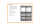
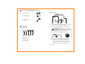
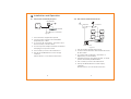
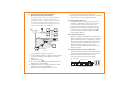
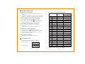
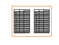
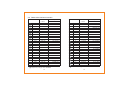
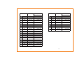
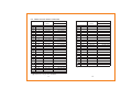
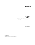
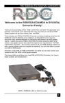
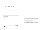
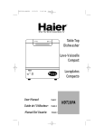
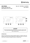
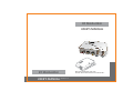
RF Modulator
USER'S MANUAL
RF Modulator
USER'S MANUAL
BEFORE OPERATING THE UNIT,
PLEASE READ THIS MANUAL THOROUGHLY
6060404014-10
SAFETY INFORMATION
CAUTION
RISK OF ELECTRONIC
SHOCK DO NOT OPEN
CAUTION:
DO NOT REMOVE THE COVER FOR REDUCING THE
RISK OF ELECTRONIC SHOCK
NO USER-SERVICEABLE PARTS INSIDE REFER
SERVICING TO QUALIFIED SERVICE PERSONNEL.
WARNING:
To prevent fire or shock hazard, do not expose
the unit to rain or moisture.
Safety term and Symbols
Warning: Warning statements identify
conditions or practices that could
result in injur y or loss of life.
Caution: Caution statements identify
conditions or practices that could
result in damage to this product or
other property.
Danger: Do not remove the cover for
reducing the risk of electric shock.
IMPORTANT SAFETY INSTRUCTIONS
1. All the safety and operating instructions should
be read before the product is operated.
2. The safety and operating instructions should be
retained for future reference.
3. All warnings on the product and in the operating
instructions should be adhered to.
4. All operating and use instructions should be
followed.
5. Unplug this product from the wall outlet before
cleaning. Do not use liquid cleaners or aerosol
cleaners. Use a damp cloth for the cleaning.
6. Do not use attachments not recommended by the
products manufacturer if they may cause hazards.
7. Do not use this product near water - for example,
near a bath tub, wash bowl, kitchen sink, or
laundry tub, in a wet basement, or near a
swimming pool; and the like.
8. Any mounting of the product should follow the
manufacturer's instructions, and should use a
mounting accessory recommended by the
manufacturer.
9. This product should be operated only from the
type of power source indicated on the marking
label. If you are not sure of the type or power
supply to your home, consult your product
dealer or local Power Company. For products
intended to operate from battery power,
or other sources, refer to the operating
instruction.
10.Power supply cord should be routed so that are
not likely to be walked on or pinched by items
placed upon or against them, paying particular
attention to cords at plugs, or other sources,
refer to the operating instructions.
11.For added protection for this product during a
lightning storm, or it is left unattended and
unused for long periods of time, unplug it from
the wall outlet and disconnect cable system.
This will prevent damage to the product due to
lightning and powerline surges.
12.Never push objects of any kind into this product
through openings as they may touch dangerous
voltage points or short-out parts that could
result in a fire or electronic shock. Never spill
liquid of any kind on the product.
13. Do not overload wall outlets, extension cords,
or integral convenience receptacles as this can
result in a risk of fire or electric shock.
14. Unplug this product from the wall outlet and
refer servicing to qualified service personnel
under the following conditions.
When the power-supply cord or plug is damaged.
If liquid have been spilled, or objects have fallen
into the products.
If the product does not operate normally by
following the operating instructions, adjust only
those controls that are covered by the operating
instructions as an improper adjustment of other
controls may result in damage and will often
require extensive work by a qualified technician
to restore this product to its normal operation.
If the products has been dropped or damaged in
any way.
When the product exhibits a distinct change in
performance - this indicates a need for service.
15. When replacement parts are required, be sure
the service technician has used replacement
parts specified by the manufacturer or that
have the same characteristics as the original
part. Unauthorized substitutions may result in
fire, electric shock, or other hazards.
16.Upon completion of any service or repair to this
product, ask the service technician to perform
safety checks to determine that the product is
in proper operating conditions.
17.The product should be situated away from heat
sources such as radiators, heat registers,
stoves, or other products including amplifiers
that produce heat.
Table of Contents
1 Introduction
1.1
1.2
1.3
1.4
............................. 1
...............................
Overview
........................
Main Features
........................
Applications
........................
Specification
1
1
1
2
2 Check package before use ....... 3
3 Controls
.................................. 3
4 Installation and Operation .........
4.1 Work with VCD/DVD players .........
4.2 Work with Satellite Receiver .........
4.3 Connect the second load when
AV source just has one output .....
4.4 Dual power sources ..................
..................
4.5 Channel selection
4.6 How to check channel selected ...
5 Trouble Shooting
5
5
6
7
8
8
8
..................... 9
5.1 No picture or sound ...................
5.2 The brightness of image
abnormal ................................
5.3 Interference the adjacent
channels ................................
5.4 LNB can not work properly ...........
..................
5.5 Distortion of sound
9
9
9
9
9
6 Channel Lists ............................. 9
6.1 Table of European Channels ........ 10
6.2 Table of Australian Channels ........ 13
6.3 Table of South Africa Channels ..... 17
1 Introduction
1.4 Specification
1.1 Overview
This stereo/mono RF modulator is a
programmable modulator which
generates an RF TV channel from a
baseband video and audio signal.
It is the practical solution of building
your home AV network. It can use
current cable network in the house to
transmit a good quality video and
audio to another room.
PAL I or PAL B/G
UHF: 470~862MHz
VHF: 126~300MHz
Europe:
Ch. 21 ~69
Ch. S4~S20, E5~E12
Australia:
Ch. 21 ~69
Ch. S4 ~ S20, 6~12
South Africa:
Ch. 21~61
Ch. 4 ~ 13
Output Power
Harmonic
Third distortion
Isolation
Insertion loss
82/72dBµV (Typical)
1.2 Main Features
PAL I for mono or PAL B/G for stereo
Dip switch channel selector
High output power up to 82dB µ V
Dual input power source
1.3 Applications
Home AV network
Hotel local TV program system
Specification
Item
Standard
Frequency Range
>55dBc
>58dBc
>20dBc
<1.5dB@800MHz
<[email protected]
Audio carrier frequency
PAL I : 5.5MHz
PAL B/G: 5.5, 5.742MHz
Audio frequency response 50-15KHz
Audio input level
1.7 Vpp max.
Separation
>20dB (Typical)
(test frequency:1KHz/1.7Vpp)
Current consumption
110mA
Input power
DC 9V/300mA for adaptor.
13/18V for satellite receiver
Power adaptor
Operating Temperature
DC 9V / 300mA
0 C ~ 50 C
85.8(L)X68.4(W)X21.3(H)
Dimension(mm)
Specification subject to change without prior notice.
1
2
2 Check package before use
1. RF Modulator
X 1
2. Power Adaptor
X 1
3. SCART to RCA
Adaptor
X 1
Bottom View
6
7
8
9
6. Left: DC source switch (DC jack power supply
only if you remove the jumper)
7. Right: Video loaded jumper (unplug when
using video splitter)
3 Controls
Rear View
Caution:
Do not plug the jumpers horizontally
for avoiding any damage in Set-top Box.
1
2
3
5
4
1. RF +1 ch output
2. RF input
3. Video Input
4. Audio Left
5. Audio Right
3
8. Channel switch: sw1 to sw7 for channel
switch, sw8 for test pattern on/off (if
sw8 is on, there will be two white bar
on TV screen on the channel that you
selected. sw9 for high / low power.
9. DC jack
4
4 Installation and Operation
4.2 Work with Satellite Receiver.
4.1 Work with VCD/DVD players.
RF Modulator
Diplexer
TV
Combiner
VCD/DVD
CATV or Terrestrial
TV
TV
TV
TV
Figure 1.
1. Turn off all A/V equipments power.
2. Connect RF modulator and VCD/DVD
players by A/V cable.
3. To connect RF modulator, Television and
RF sources by coaxial cable.
4. Connect power adaptor with RF modulator
and plug it into power socket.
5. Turn on the A/V source and television.
6. Set up the RF Modulator on the empty
channel.
Please refer to "4.5 Channel selection"
LNB
AV
Receiver
RF Modulator
Figure 2.
1. Turn off all A/V equipments power.
2. Connect RF modulator and satellite receiver
by A/V cable.
3. To connect RF modulator, Television or
Diplexer by coaxial cable.
4. Satellite receiver can supply power, no extra
power needed by RF Modulator.
5. Turn on the A/V source and television.
6. Set up the RF Modulator on the empty
channel.
Please refer to "4.5 Channel selection"
5
6
4.3 Connect the second load when
AV source has just one output
This RF Modulator offers an extended loop
through function. Satellite receiver can
transmit program to the TV beside it through
AV cable with high quality AV signal, and
it can also transmit the program to the other
rooms through the RF modulator.
Diplexer
Combiner
TV
TV
TV
TV
Receiver
LNB
AV
SCART to RCA
AV
TV
AV
RF Modulator
Figure 3.
1. Turn off all A/V equipments power.
2. Connect RF modulator , television and satellite
receiver by SCART to RCA Adaptor .(refer to
Figure 3.)
3. Remove jumper 7 .
4. To connect RF modulator, satellite receiver or
Diplexer by coaxial cable.
5. Satellite receiver can supply power, no extra
power needed by RF Modulator.
Please refer to "4.4 Dual power sources".
7
6. Turn on the A/V source and television.
7. Set up the RF Modulator on the empty channel.
Please refer to "4.5 Channel selection"
4.4 Dual power sources
The RF Modulator can use the power from
adaptor or satellite receiver. If you connect
to both power source at same time, the
higher one will be used ( normally, the DC
power from satellite receiver will be 13/18V,
the adaptor is 9V). Remove the jumper 6
can force the modulator using the power
from Power Adaptor.
4.5 Channel selection
This RF modulator is designed in double side
band modulation that occupies two channel
space. The program you are going to have in
your home network should be placed at the
higher channel of at least two continuous
empty channels, and it is better to set
program on the middle of three continuous
empty channel.
4.6 How to check channel selected
This RF Modulator offers an internal video test
pattern- if you switch sw8 to 1, and TV screen
shows up black and white bars, that is
you have gotten the correct channel.
E5:11010010
Switch sw8 to 1
ON
ON
1 2 3 4 5 6 7 8 9
1 1 0 1 0 0 1 0
1 2 3 4 5 6 7 8 9
1 1 0 1 0 0 1 1
Internal video test pattern
8
5 Trouble Shooting
5.1 No picture or sound
6.1 Table of European Channels
Check all the cables well and connected
rightly.
Check the channels correctly set up. Please
refer to "4.6 How to check channel selected".
5.2 The brightness of image abnormal
Too light: Check jumper 7 plug rightly
Too dark: Check jumper 7 removed if there
is other loading or it is connecting with TV.
5.3 Interfere the adjacent channels:
Re-set up the program to other empty
channel.
Please refer to "4.5 Channel Selection".
5.4 LNB can not work properly
Remove jumper 6 and plug power
adaptor to force RF modulator consuming
power from socket outlet instead of that
from satellite receiver.
5.5 Distortion of sound
Turn down the volume of AV source.
6 Channel Lists
Adjust Dip switch to get the channel.
E5:11010010
ON
1 2 3 4 5 6 7 8 9
1 1 0 1 0 0 1 0
E6:00110010
ON
1 2 3 4 5 6 7 8 9
0 0 1 1 0 0 1 0
9
Video
Switch position
carrier
12345678
A
53.75
11100010
00010010
E2
48.25
10010010
E3
55.25
01010010
E4
62.25
E5
175.25
11010010
E6
182.25
00110010
E7
189.25
10110010
E8
196.25
01110010
11110010
E9
203.25
00001010
E10
210.25
E11
217.25
10001010
01001010
E12
224.25
10000000
S1
183.75
01000000
S2
192.25
11000000
S3
201.25
00100000
S4
126.25
10100000
S5
133.25
01100000
S6
140.25
S7
147.25
11100000
S8
154.25
00010000
S9
161.25
10010000
S10
01010000
168.25
S11
231.25
11010000
00110000
S12
238.25
S13
10110000
245.25
01110000
S14
252.25
259.25
11110000
S15
Frequency range:126-300MHz
Channel
10
Video
Switch position
carrier
12345678
S16
266.25
00001000
10001000
S17
273.25
01001000
S18
280.25
11001000
S19
287.25
S20
294.25
00101000
21
471.25
10101000
22
479.25
01101000
23
487.25
11101000
00011000
24
495.25
10011000
25
503.25
26
511.25
01011000
11011000
27
519.25
00111000
28
527.25
10111000
29
535.25
01111000
30
543.25
11111000
31
551.25
00000100
32
559.25
10000100
33
567.25
34
575.25
01000100
35
583.25
11000100
36
591.25
00100100
37
10100100
599.25
38
607.25
01100100
11100100
39
615.25
40
00010100
623.25
10010100
41
631.25
639.25
01010100
42
Frequency range:126-300MHz
Channel
11
Video
Switch position
carrier
12345678
43
647.25
11010100
00110100
44
655.25
10110100
45
663.25
01110100
46
671.25
47
679.25
11110100
48
687.25
00001100
695.25
49
10001100
703.25
50
01001100
11001100
711.25
51
00101100
719.25
52
727.25
53
10101100
01101100
735.25
54
11101100
55
743.25
00011100
56
751.25
10011100
57
759.25
01011100
58
767.25
11011100
59
775.25
00111100
60
783.25
61
791.25
10111100
62
799.25
01111100
63
807.25
11111100
64
815.25
00000010
65
823.25
10000010
01000010
66
831.25
67
11000010
839.25
00100010
68
847.25
855.25
10100010
69
Frequency range: 470-860MHz
Channel
12
6.2 Table of Australian Channels
Video
Switch position
carrier
12345678
S4
126.25
01010010
S5
133.25
11010010
S6
140.25
00110010
S7
147.25
10110010
S8
154.25
01110010
S9
161.25
11110010
S10
168.25
00001010
S11
231.25
10001010
S12
238.25
01001010
S13
245.25
11001010
S14
252.25
00101010
S15
259.25
10101010
S16
266.25
01101010
11101010
S17
273.25
S18
00011010
280.25
S19
10011010
287.25
S20
01011010
294.25
S21
11011010
303.25
S22
00111010
310.25
S23
10111010
317.25
S24
01111010
324.25
S25
331.25
11111010
S26
338.25
00000110
S27
345.25
10000110
S28
352.25
01000110
S29
359.25
11000110
S30
366.25
00100110
Frequency range:126-300MHz
Channel
13
Video
Switch position
carrier
12345678
S31
373.25
10100110
01100110
S32
380.25
11100110
S33
387.25
00010110
S34
394.25
S35
401.25
10010110
S36
408.25
01010110
415.25
S37
11010110
422.25
S38
00110110
10110110
429.25
S39
01110110
436.25
S40
443.25
S41
11110110
01100000
175.25
6
11100000
7
182.25
00010000
8
189.25
10010000
9
196.25
01010000
10
209.25
11010000
11
216.25
00110000
12
224.25
21
478.25
10101000
22
485.25
01101000
492.25
23
11101000
24
499.25
00011000
25
506.25
10011000
01011000
26
513.25
11011000
520.25
27
00111000
28
527.25
534.25
10111000
29
Frequency range: 470-860MHz
Channel
14
Channel
30
31
32
33
34
35
36
37
38
39
40
41
42
43
44
45
46
47
48
49
50
51
52
53
54
55
56
Video
carrier
541.25
548.25
555.25
562.25
569.25
576.25
583.25
590.25
597.25
604.25
611.25
618.25
625.25
632.25
639.25
646.25
653.25
660.25
667.25
674.25
681.25
688.25
695.25
702.25
709.25
716.25
723.25
15
Switch position
12345678
01111000
11111000
00000100
10000100
01000100
11000100
00100100
10100100
01100100
11100100
00010100
10010100
01010100
11010100
00110100
10110100
01110100
11110100
00001100
10001100
01001100
11001100
00101100
10101100
01101100
11101100
00011100
Video
Switch position
carrier
12345678
57
730.25
10011100
58
737.25
01011100
11011100
59
744.25
00111100
60
751.25
10111100
61
758.25
01111100
62
765.25
11111100
63
772.25
779.25
00000010
64
786.25
10000010
65
793.25
01000010
66
800.25
11000010
67
807.25
00100010
68
10100010
69
814.25
Frequency range: 470-860MHz
Channel
16
6.3 Table of South Africa Channels
Video
Switch position
carrier
12345678
01010010
4
175.25
5
183.25
11010010
00110010
6
110.25
10110010
7
199.25
207.25
01110010
8
215.25
11110010
9
00001010
223.25
10
10001010
11
231.25
13
247.425
11001010
21
471.25
10101000
22
479.25
01101000
487.25
23
11101000
24
495.25
00011000
25
503.25
10011000
01011000
26
511.25
11011000
519.25
27
00111000
28
527.25
535.25
10111000
29
30
543.25
01111000
31
551.25
11111000
32
559.25
00000100
33
567.25
10000100
34
575.25
01000100
35
583.25
11000100
36
591.25
00100100
37
599.25
10100100
38
607.25
01100100
Frequency range:126-300MHz
Channel
17
Video
carrier
Switch position
12345678
39
11100100
615.25
40
00010100
623.25
10010100
631.25
41
01010100
639.25
42
43
11010100
647.25
00110100
655.25
44
10110100
45
663.25
01110100
46
671.25
11110100
679.25
47
687.25
48
00001100
695.25
10001100
49
50
703.25
01001100
51
711.25
11001100
52
719.25
00101100
53
727.25
10101100
54
735.25
01101100
55
743.25
11101100
56
751.25
00011100
57
759.25
10011100
58
767.25
01011100
11011100
59
775.25
00111100
60
783.25
10111100
61
791.25
Frequency range: 470-860MHz
Channel
18