1
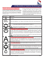
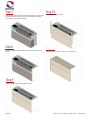
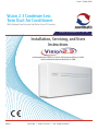
Issue 1.2 May 2015
Vision 2.3 Condenser-Less
Twin Duct Air Conditioner
With Optional Low Pressure Hot Water Fan or DC Inverter
w w w. p ow r m a t i c. co. u k
Installation, Servicing, and Users
Instructions
Including data for the Vision 2.3, Vision 2.3 DC inverter and Vision 2.3 LTHW,
with assembly instructions for the Vision 2.3 LTHW
GB & IE
HEATING // VENTILATION // AIR CONDITIONING
powrmatic
Certificate of Guarantee
Dear Customer
This is to certify that this air conditioner has a parts only one year warranty from the date of
original commissioning. The air conditioner must be commissioned within 4 weeks of
installation.
To make a claim
In the first instance you must contact your appliance supplier, or installer and provide:1.
The appliance type and serial number.
2.
The original commissioning documentation.
3.
As much detail as possible on the fault.
Your supplier, or installer, will then contact Powrmatic to make a guarantee claim
on your behalf.
Conditions of Guarantee
1.
2.
3.
4.
5.
6.
7.
8.
The air conditioner must have been installed by a competent recognised
installer, and in accordance with the manufactures instructions, building
regulations and local regulations.
The air conditioner has been professionally commissioned, within 4 weeks of
installation, and a copy of the Commissioning sheet returned to Powrmatic.
The air conditioner has been maintained on a yearly basis by a competent
servicing company.
The air conditioner has been used in accordance with the manufactures
instructions.
The correct specification voltage has been used.
No unauthorised repairs or modifications have been made.
Powrmatic ‘General Conditions of Sales’ have been observed.
Except for the obligation of Powrmatic Ltd to perform warranty repairs during the
guarantee period Powrmatic will not be liable in respect of any claim for direct or
indirect consequential losses, including loss of profit or increased cost arising
from loss of use of the air conditioner, or any event arising there from.
-------------------------------------------------------------------
Powrmatic Ltd. Hort Bridge, Ilminster, Somerset, TA19 9PS
Tel: 01460 53535
Fax: 01460 52341
Web: www.powrmatic.co.uk e-mail [email protected]
Important :This certificate must
be kept with the appliance
Installer
Date :_____________ Signed ____________________________________________Installer
Commissioned
Date :_____________ Signed _______________________________Commissioning Engineer
Page 2
Vision 2.3 Air Conditioner Range Issue 1.2 May 2015
Dear Customer - thank you for choosing Powrmatic.
We appreciate you buying one of our high quality products and know that you have made the best
choice. We pride ourselves by manufacturing products that provide clean, comfortable and safe
working environments worldwide together with the personal & professional service and back-up you
deserve. If you have any questions or concerns regarding this product, please contact our Technical
Support Team by calling 01460 53535.
Compliance
This unit complies with European directives:
• Low voltage 2006/95/EC
• Electro-magnetic compatibility 2004/108/EC
• Use restrictions of hazardous substances in
electrical and electronic 2011/65/EC
(RoHS2)
•
•
Waste electrical and electronic equipment
2002/96/EC(WEEE)
Energy consumption indication on the labels
of energy related products 2010/30/EU
Symbols
Pictograms in the next chapter provides the necessary information for a correct and safe use of the
machine in a rapid, unmistakable way.
Editorial pictograms
U
User
Refers to pages containing instructions of
information for the user.
I
Installer
Refers to pages containing instructions or
information for the installer.
S
Service
Refers to pages containing instructions or
information for the CUSTOMER TECHNICAL
ASSISTANCE SERVICE installer.
Vision 2.3 Air Conditioner Range Issue 1.2 May 2015
Safety pictograms
Warning
It indicates actions that require caution and a
suitable preparation.
Do Not
Refers to actions that absolutely must not be
performed.
Page 3
Users, Installation, Servicing and User Instructions
Troubleshooting
Title
CONTENTS
Section
Contents
General
1.1
1.2
1.3
1.4
1.5
1.6
1.7
1.8
1.9
General warning
Fundamental safety rules
Description
Receipt and unpacking
Storage
Handling
Shipping dimensions and weight
Supplied components
Unit parts
Installation
2.1
2.2
2.3
2.4
2.5
2.6
2.7
2.8
2.9
2.10
Installation mode
Choosing the position of the unit
Assembling the unit
Assembling air ducts and external shutters
Mounting the appliance on the bracket
Electrical connection
High/Low installation configuration
Setting cool only or heat only modes
Touch-screen display key lock
Operations tests and anomaly diagnosis
9
9
10
12
13
13
14
16
16
16
Troubleshooting
3.1
3.2
3.3
Periodic Maintenance
Troubleshooting
Technical data
17
18
19
User Manual
4.1
Management of the appliance with the
touch-screen display
Managing the appliance with the remote
control
Description of machine functioning
Advice for energy saving
4.2
4.3
4.4
appendex.
Page 4
5.1
Page
Assembly instructions for the
Vision 2.3 LTHW
5
5
6
6
6
6
7
7
8
20
20
21
23
24
Vision 2.3 Air Conditioner Range Issue 1.2 May 2015
1.1 General Warning (UIS)
After unpacking, check that the contents are
intact and that all parts are included. If they are
not, please contact the supplier who sold you the
appliance.
If the temperature is set too low or too high, not
only will it be unhealthy, but it is also a waste of
energy. Avoid prolonged direct contact with the
air flow.
The appliance must be installed by an authorised Installer. Once the work is done, they must
issue a declaration of conformity to the client in
compliance with current regulations and with
indications on this instruction manual supplied
with the appliance.
Do not leave the room closed for long periods.
Open the windows periodically to change the air.
These appliances have been designed for conditioning and heating rooms, and they must be
destined solely for this purpose compatible with
their performance characteristics.
The manufacturer refuses any contractual or
extra-contractual responsibilities for damage
caused to people, animals, or things resulting
from incorrect installation, adjustment, maintenance or improper use.
This instruction booklet is an integral part of the
appliance and therefore it must be kept safely
and must ALWAYS accompany the appliance
even when the later is transferred to another
owner or user, or moved or sold. If it gets damaged or lost, please request another copy.
Any repair or maintenance operation must be
performed by a qualified person in accordance
with this booklet. Do not modify or tamper with
the appliance as this could lead potential danger
and the manufacturer will not be liable for any
damage caused.
In the event of water leaks, turn off the main
switch and close the water taps.
Immediately call the Technical Assistance
service or other qualified personnel and do not
intervene personally on the appliance.
1.2 Fundamental safety rules (UIS)
We would like to remind you that some fundamental safety rules should be followed when
using products that work with electricity and
water.
The use of the appliance by children and unassisted disabled persons if forbidden.
It is forbidden to pull out or twist the electric
cables coming out of the appliance, even if they
are disconnected from the pains power supply.
It is forbidden to introduce objects and substances though the air inlet and outlet grids.
It is forbidden to touch the appliance if barefooted or with wet or damp parts of the body.
It is forbidden to open the access doors to the
internal parts or the appliance without having
turned off the mains switch first.
It is forbidden to clean the appliance without
having first disconnected the appliance from the
mains power supply by turning off the mains
switch.
It is forbidden to leave the packing material
within the reach of children as they could be a
source of danger. This material should be recycled or disposed of properly.
It is forbidden to modify or adjust safety devices
without authorisation and instructions from the
manufacturer.
It is forbidden to climb onto the appliance and/or
to place any type of object on top of it.
Vision 2.3 Air Conditioner Range Issue 1.2 May 2015
Page 5
1.3 Description (UIS)
The Vision 2.3 is the new solution by Powrmatic, a significant step towards reducing the aesthetic impact of air
conditioners. Being only 16 centimetres deep, the Vision
2.3 is the thinnest and less bulky in this category, therefore both the internal and external aesthetic impact is kept
to a minimum.
Optimised Capacities
The conditioning capacity of the Vision 2.3 have been
optimised so as to obtain the right temperature for the
best level of comfort and, therefore less consumption and
less noise. Thanks to the careful choice of sound insulation materials, the noise is similar to that of a standard
wall split unit and consumption is drastically contained
thanks to the new direct current fan.
162 millimetre holes
An important choice, not only design-wise, but also
because of a considerable installation advantage: it is
easier to find drilling tools, with lower aesthetic impact.
Easy to install
The Vision 2.3 can be installed on any perimeter wall
either low or high. Everything needed for installation
(template, support bracket, hole pipes and external grids),
excluding the drill, is included in the box.
Folding external grids
Remote control and touch screen display.
In addition to the remote control, the touch screen display
on the unit enables the setting of any function. There is
even a ‘lock’ mode to avoid any improper use. It is possible to deactivate the ‘heating’ mode by simply touching
the screen. the unit then works in ‘cool only’ mode,
without the need to use the condensation drain pipe. The
orientation of the air flap can also be adjusted by simply
pressing one key.
1.4 Receipt and unpacking (UIS)
report it to the delivery company within 3 days of
receipt by registered letter with return receipt
and attaching photographic documentation. A
copy should also be sent by fax/email to the
MANUFACTURER. No notice of damage will be
accepted after 3 days from delivery.
The packing is made of suitable material and carried out
by expert personnel. All units are checked and tested and
are delivered complete and in perfect condition. However
please perform the following instructions to check the
condition of the received product:
Upon receipt , check if the box is damaged. If
that is the case, accept the goods with reservations and keep photographic evidence of any
damage found.
Unpack and check the contents against the
packing list.
Check that none of the parts have been damaged during shipment. In case of damage,
Keep the packing for at least the length of the
warranty should you need to return the appliance to the service centre for repair. dispose of
the packing materials in compliance with current
regulations on waste disposal.
1.5 Storage (UIS)
If the conditioner is not to be installed immediately, store
the box in a closed environment, protected from atmospheric agents and isolate it from the floor using planks or
pallets.
Do not turn upside down.
1.6 Handling (UIS)
The unit is packed singularly in a cardboard box. Boxes
can either be carried singularly by hand by two operators
or loaded on trolley, maximum three units high.
Handling must be performed by qualified
personnel, with specific tools and with equipment suitable for the weight of the equipment.
Page 6
The appliance is unbalanced on the right (compressor side)
During transportation, the appliance must be
kept in a upright position.
Vision 2.3 Air Conditioner Range Issue 1.2 May 2015
1.7 Shipping dimensions and weight (UIS)
Packing
Dimensions
Weight
Length
Height
Depth
“Vision 2.3” 10 HP
Kg
mm
mm
mm
50
1110
660
260
1.8 Supplied components (UIS)
The air conditioner supplied comprises of the parts listed
in the following table. Before assembly, please check that
they are all included.
A
B
C
D
E
F
External grids for air inlet and outlet with springs
and chains (2 pcs)
Screws and plugs kit (6 pcs)
Bracket for wall mounting
User manual
Remote control
Paper template for holes
Vision 2.3 Air Conditioner Range Issue 1.2 May 2015
G
H
I
L
M
N
O
CR2025 3V remote control battery
Wall inlet pipes (2 pcs)
Energy efficiency label
Bottom cover
Screws for mounting the bottom cover (2 pcs)
Installation manual
Internal flange (2 pcs)
Page 7
1.9 Unit parts (UIS)
1
2
3
4
5
6
Page 8
Air outlet flaps
Touch-screen display
Front panel
Outdoor air suction
Outdoor air outlet
Air suction grid
7
8
9
10
11
12
Air filters
Outdoor air outlet fan
Outdoor air heat exchanger
Compressor
Indoor air heat exchanger
Electronic board
Vision 2.3 Air Conditioner Range Issue 1.2 May 2015
2.1Installation mode (I)
Before installing the conditioner, it is essential to calculate
the summer thermal loads (and winter ones for the
models with a heat pump) of the room. The more accurate calculations, the better the product will work. Please
refer to current regulations to carry out calculations. For
big installations please call a study specialised in thermodynamics. Try to reduce the thermal refrigeration load of
the room following these instructions:
Cover large windows exposed to sunlight with curtains or
with external masking (blinds, porches, reflecting films
etc.)
The room must remain closed for as long as possible.
Avoid using halogen lamps or other high energy
consumption appliances such as small ovens, steam
irons, cooking plates etc.
2.2 Choosing the position of the unit (I)
For a better performance of the appliance and to avoid
malfunctions or dangerous situations, the location of the
unit must meet the following requisites:
Respect the minimum distances indicated in the
picture.
The wall on which you wish to anchor the unit
must be robust to support its weight.
Leave enough space around the unit to perform
maintenance operations.
Nothing must obstruct the air flow both in the top
suction part (curtains, plants, furniture) and in
the lower outlet part, as it could cause vibrations
which might prevent the appliance form working
correctly.
The appliance must be installed against a wall
connecting with the outside.
Vision 2.3 Air Conditioner Range Issue 1.2 May 2015
Check that there are no structures or systems
(beams, pillars, hydraulic pipes, electrical cables
etc.) in the part of the wall that must be drilled.
Check that nothing is placed in front of the holes
thus obstructing the air flow (plants and leaves,
panels, shutters, grates, etc)
The unit should not be installed in a position
where the air flow aims directly at people nearby.
Do not force the air flap open.
The appliance must not be installed directly
above, or below another electrical appliance
(TV, radio, fridge, etc.) or above a source of
heat.
Page 9
2.3 Assembling the unit (I)
The maximum length of the holes is of 1 m and
there must be no bends. Use the supplied grids
or grids with the same characteristics.
The holes must be drilled slightly downward
towards the outside, to avoid water from entering
the building.
For the unit to work, two holes must be placed as indicated on the template.
The majority of the removed material is expelled outwards
so please be careful that it does not hit people or objects.
In order to avoid breaking the outer plaster, be careful
while drilling the final part of the hole and ease the pressure on the core drill.
Drill the 6 holes for the bracket as indicated on the
template.
The appliance weights more on the right side, so make
sure it is properly supported on this side. The holes must
have an 8mm diameter to accommodate the 6 supplied
plugs.
In any case, check the characteristics and the consistency of the wall to see whether specific plugs may be
needed.
The holes on the wall must be drilled using suitable equipment that does not cause damage or excessive inconvenience to your client. The best tools to make big holes are
special drills (called “core drills”) with a high torque and
whose speed can be adjusted according to the diameter
of the hole and the material to be drilled. In order to avoid
excesses dust and debris in the room, “core drills” can be
combined with suction systems composed of a vacuum
connected and a suction cup which can be placed next to
the drill. In order to make the holes, proceed as follows.
Place the template provided against the wall,
respecting the minimum distances from the
ceiling, the floor, and the side walls, as indicated
on the template. The template can be held in
place using adhesive tape. A spirit level can be
used to ensure the unit is square.
Mark the centre of each hole with a small drill or
a punch before actual drilling commences.
Using the core drill, make two holes for the inlet
and outlet air.
A
B
C
D
Page 10
The manufacturer cannot be held responsible for
any underestimates or the structural consistency
of the anchoring arrangement made by the
installer. We therefore encourage you to pay the
utmost attention to the operation, as if performed
badly it could cause serious injury or damage.
Drill a hole in the position indicated on the template for
those heat pump appliances without a condensation drain
built in the wall in order to enable the drainage of condensation.
Holes for M8 Plugs
Electrical connection area
Ø162mm holes for air channelling
Ø14mm condensation drain
Vision 2.3 Air Conditioner Range Issue 1.2 May 2015
Condensation drain predisposition
The exact position in which to place the pipe
mouth is indicated on the template.
For heat pump appliances, a condensation drain pipe
(Ø10mm, internal, not supplied) must be connected to the
pipe on the top part of the appliance.
A solenoid valve will start the flow of the condensation
from the internal collection tray when the maximum level
has been reached. For cooling only appliances, said pipe
must be connected if the appliance is going to be used
with low external temperatures, (below 23oC). As it is a
gravity drain, it is essential for the line to have at least 3%
slope minimum at every point. A rigid or flexible pipe can
be used with a minimum internal diameter of 10mm. If the
line flows into a sewage system, it is necessary to be
trapped before connecting to the drain. Said trap must be
placed at least 300mm under the mouth of the appliance.
Check that the expelled water does not cause
any damage, or problem to people or objects.
During winter this condensation can freeze to
form ice on pathways.
When connecting the condensation drain, be
careful not to squeeze the rubber duct.
It is possible to empty the collecting tray using
the safety drain at the base of the appliance if
necessary.
If the line flows into a container (e.g. a tank) do
not close the container hermetically and avoid
immersing the draining pipe into the water.
The hole for the condensation pipe must always
lean towards the outside.
1
2
Safety drain to empty tray
Condensation drain duct
2.1 Fitting the unit
Vision 2.3 Air Conditioner Range Issue 1.2 May 2015
Page 11
2.4 Assembling air ducts
and external shutters (I)
Once the holes have been made, place the supplied
plastic sheet inside them.
Roll up the sheet and insert it in the hole, checking that
the joint is facing upwards.
Use a cutter to remove any excess pipe.
To place the external grids, proceed as follows:
Connect the chains to the ends of the springs.
Fold the external shutters.
Insert your arm in the hole to push the shutter to
the outside, whist holding the the chain with the
other hand to prevent the shutter from falling.
Open the shutter inside the hole.
Rotate the shutter to bring the flat into the vertical “C” position and check that the closing mechanism works.
Pull the chains by tensioning the springs.
Insert the internal flange in the hole with the
internal hooks in the vertical position.
-
Fix the chains to the internal flange’s hooks
Use a bolt cutter to remove any excess chain.
Anchor the hook of the chain to wall “B”.
Use only the supplied grids or grids with the
same characteristics.
The grids must be positioned with the flaps vertical.
The shutters are different. Check the opening of
the shutter to determine if they are the inlet or
outlet shutter, and fit accordingly.
A
B
C
Junction line
Internal flange
Flap in vertical position
IN
OUT
Page 12
Vision 2.3 Air Conditioner Range Issue 1.2 May 2015
2.5 Mounting the appliance on the bracket (I)
After checking that the bracket is anchored to the wall and
that all necessary electrical connections and condensation drain have been made, you can mount the conditioner. Lift it by the sides of the bottom base until the bracket
fits on all of the right spots on the appliance. In order to
ease the operation, slightly tilt the appliance towards you.
Direct electrical connections (disconnecting the power
supply cable) and the anchoring of the condensation
drain must be carried out after having spaced the appliance from the wall using wooden wedges or any other
similar object.
Once the work is done, check that there are no openings
on the back of the appliance especially where the air
ducts are connected.
1
2
Bracket
Bracket anchoring points
2.6 Electrical connection (I)
The appliance is equipped with a power cord and plug
(Y-type connection, the cord can only be replaced by the
manufacturer, the assistance centre or a qualified installer) If using a socket near the appliance, insert the plug.
Before connecting the conditioner check that:
-
The appliance must be connected to 230V/50Hz
mains via an omnipolar switch with a contact
opening distance of a minimum of 3mm, or using
a device enabling the complete disconnection of
the appliance in overvoltage III category conditions.
The power supply voltage and frequency values
comply with the data plate of the appliance.
The power supply line is provided with a suitable
earth connection and that it is dimensional for
the maximum absorption of the conditioner (minimum cable section equal to 1.5mm2)
Power is only supplied using a suitable socket
through a supplied plug.
It is possible to carry out the electrical connection using a
cable inside of the wall as indicated in the installation
template (recommended for installations in the upper part
of the wall)
Please check that the power supply is provided with
suitable protections against overloads and/or short
circuits (using a 10 at delay fuse or other equivalent
devices is recommended)
The power cord must be replaced only by the
technical assistance service or by authorised
personnel.
This operation must be performed only by the
installer or by authorised personnel in compliance with current national regulations.
Vision 2.3 Air Conditioner Range Issue 1.2 May 2015
Page 13
It is essential to disconnect the main switch before making
any connection or maintenance operation in order to
avoid any risk of electrocution.
To carry out direct connections and substitute the power
cord using the cable in the wall, proceed as follows:
Space the appliance from the wall using wooden
wedge or a small object.
Disconnect the power cord by unscrewing the 3
screws from the terminal board.
Connect the wall cable checking that the power
supply line is provided with a suitable earth
connection and that it is dimensioned for the
maximum absorption of the conditioner (minimum cable section equal to 1.5mm2)
CP presence contact input connection
When the CP contact opens (connected to a free non-live
contact) the appliance is put in standby and CP appears
on the display.
Using this contact it is possible to connect an external
device that inhibits the function of the appliance such as
open window contact, remote control on/off, infrared presence sensor, qualification badge etc.
A 230V50Hz Electrical power supply terminal board
B CP pressence contact
These operations must be carried out with the
appliance already placed on the bracket, therefore read the following instructions carefully
before completing the connection.
2.7 High/Low installation configuration (I)
The unit can be installed either at high level or low level on
the wall, in order to optimise air distribution and comfort,
the direction of the air flow can be modified by adjusting
the position of the air flap.
The appliance is supplied ready to be installed in the
lower part of the way, so air is dispensed upwards. The
same configuration can also be used high on the wall in
cooling mode, which increases the air flow in the room
(coanda effect)
This operation must be performed whilst the
appliance is switched off and disconnected.
Modifications from lower wall to the
upper wall position
Page 14
1
2
3
4
5
6
the lower hole.
Remove the upper grill.
Remove the two plastic side panels by moving
them up.
Unscrew the fixing screws
Remove the front panel
Place the bottom cover and fix it with the
supplied screws.
Refit in the reverse order.
Block insert
Bottom cover
Fixing screws
Upper grill
Plastic side panels
Front panel
Open the air outlet flap gently.
Remove the flap opening block insert located
internally on the air outlet mouth and place it in
Vision 2.3 Air Conditioner Range Issue 1.2 May 2015
After adjusting the air outlet flap position, it is necessary to
set up the electronic control of the appliance:
Press and hold the
button on the display for
5 seconds.
The “dn” (lower wall) symbol lights up on the
display.
Press the
button again.
The “uP” (upper wall) symbol lights up on the
display.
Vision 2.3 Air Conditioner Range Issue 1.2 May 2015
-
If no other operations are performed in the
following 2 seconds, the new setting is memorised.
For the appliance to work properly, each time the
configuration of the air outlet flap is modified the
electronic control must be set.
Page 15
2.8 Setting cool only or heat only modes (I)
It is possible to deactivate the heating or the cooling
modes following a simple procedure.
Pres and hold the “A” key for 5 seconds until the “HC”
(heating and cooling) appears on the display.
Press the “A” key for 1 second for the Co (cooling only)
mode.
Press the “A” key for Ho (heating only) mode.
Wait for 3 seconds without touching anything to memorise
the setting.
2.9 Touch-screen display key lock (I)
The key lock is activated by press and hold the Timer
symbol for 3 second.
The key pad is then locked and no operations are available to the user.
The stand-by symbol flashes at 1 second intervals.
To deactivate the lock, press and hold the Timer
symbol for 3 seconds.
Any key on the remote control will also deactivate the
lock!
2.10 Operations, tests
and anomaly diagnosis (I)
The conditioner can perform a short self-diagnosis cycle
to check the temperatures detected by the 4 probes and
the status of the 3 inlets.
In order to activate the self diagnosis function, press the
button within 10 seconds from the electric power
being turned on.
The display will light all symbols for 2 seconds and then it
will show the 7 test information at 2 second intervals.
After 5 cycles, or when any key is pressed either in the
display or on the remote control, the self diagnosis mode
will stop.
If the conditioner stops because of an alarm (see the
following table), please contact the supplier with the code.
Display code
E1
E2
E3
E4
E5
E6
E7
Cause
Broken room temperature RT probe
Broken evaporative battery IPT probe
Broken outdoor air temperature OT probe
Broken conditioner battery OPT probe
Broken indoor air fan motor
Broken outdoor air fan
Lack of communication with the display
Open CP contact
If the contact is not closed on the CP connections the
appliance will not start and the CP alarm appears on the
display.
Page 16
Emergency condensation air discharge
Should any anomaly occur in the condensation water
system, the maximum level float blocks the conditioner
and the OF code appears on the display.
During cooling and dehumidification, electronics switch
the compressor off and keeps the water distribution
system active with the battery - together with the fan - to
disperse excess water in the container. If the problem
persists, please contact the assistance service.
During heating, condensation should drain freely through
the specific pipe. In the event of an alarm, check that the
condensation pipe is not bent or obstructed, thus preventing the water from flowing out.
Operation after installing
Before leaving, collect the packaging and clean any dust
on the appliance with a damp cloth. These operations,
though not strictly essential, transmit a sense of professionalism to the user.
In order to avoid unnecessary calls from the user, it is
best, before leaving to :
Explain the contents of the Manual.
Explain how to clean the filter.
Clarify when and how to call the Assistance
Service.
Vision 2.3 Air Conditioner Range Issue 1.2 May 2015
3.1Periodic Maintenance (S)
The air conditioner you have bought has been designed
to keep maintenance operations to a minimum, which
only concern the following cleaning operations.
-
External cleaning
-
Before any cleaning and maintenance operation
disconnect the unit from the mains by switching
off the mains switch.
Clean the air filter after a period of continuous
use and in accordance with the concentration of
impurities in the air, or when you wish to start-up
the appliance after a period of inactivity.
The filter is placed on the top part of the appliance.
Do not use abrasive sponges or abrasive or
corrosive detergents to avoid damaging the
varnished surfaces.
To extract the filters:
Open the grid and remove it.
Extract the filter by lifting them.
Remove the dust from the filter with a vacuum
cleaner or wash the unit in running water without
detergents or solvents and leave to dry.
Put the filters back on top of the batteries, taking
care to position them correctly.
Put the grid back.
-
When necessary, clean the external surfaces with a soft
damp cloth.
Check that the panel is mounted correctly after
cleaning operations.
Cleaning filter
Using the appliance without the filter is prohibited.
Wait until the parts have cooled down to avoid
getting burned.
The air conditioner you have bought has been designed
to keep maintenance operations to a minimum, which
only concern the following cleaning operations:
Vision 2.3 Air Conditioner Range Issue 1.2 May 2015
Page 17
3.2 Troubleshooting (S)
In case of a malfunction, please refer to the following
table. If, after performing the suggested checks, the probAnomaly
The appliance
does not switch
on.
Possible cause
No power supply
Batteries have run out
The appliance
does not cool/
heat enough.
The set temperature is too high
or too low.
The air filter is clogged.
Check that there is no other
obstructions blocking air flow
either internally or externally
The thermal refrigeration load has
increased (for example, a door or
window has been left open or an
appliance has been installed in the
room, generating heat (ie computer,
or fridge))
lem is not solved, please contact the authorised technical
assistance.
Solution
Check you have a power supply to the unit (try turning on a
light switch, or plugging in another electrical device.)
Check that the exclusive magneto-thermic switch that
protects the appliance has not engaged (if it has, reset it). If
the problem repeats immediately contact the supplier for
assistance)
Check that the appliance turns on by the touch screen display,
and change batteries.
Check and adjust the temperature on the remote.
Check the air filter and clean if it is necessary.
Remove anything that might block the air flow.
Try to reduce the thermal refrigeration load of the room with
the following advice:
Cover large windows exposed to sunlight with curtains or
with external masking (blinds, porches, reflecting films. etc)
The room must remain closed for as long as possible.
Avoid turning on halogen lamps or other high energy
consumption appliances such as small ovens, steam irons,
cooking plates etc.)
Display alarms
An alarm code appears on the display in case of anomalies. Some of the functions remain active (see FUNCTIONING column)
Alarm display
E1
Code
Broken room temperature RT sensor
E2
E3
Broken internal battery IPT sensor
Broken outside temperature OT
sensor
Broken out side battery OPT sensor
E4
E5
E6
E7
CP
Broken internal ventilator motor
Broken external ventilator motor
Lack of communication with the
display
Open CP contact
OF
Maximum level float intervention
Page 18
The only way to solve the problem is to disconnect and
reconnect the appliance, if the alarm still appears, please
contact the authorised technical assistance.
Functioning
It is still possible to activate the Cooling, Dehumidification
and Heating modes. It only monitors the antifreeze function
of the internal battery.
None of the functioning modes work.
None of the functioning modes work.
It is still possible to activate the Cooling, Dehumidification
and heating modes. Defrosting is performed at fixed times.
None of the functioning modes work.
None of the functioning modes work.
None of the functioning modes work.
The appliance only works if the contact is closed. Check
that the clamps are connected.
During cooling and dehumidification, electronics switches
the compressor off and keeps the water distribution system
active with the battery - together with the fan - to disperse
excess water in the container. During heating,
condensations should drain freely through he specific pipe.
In the event of an alarm, check that the condensation pipe is
not bent or obstructed, thus preventing the water from
flowing out.
Vision 2.3 Air Conditioner Range Issue 1.2 May 2015
3.3 Technical data (S)
Please read the data plates to obtain the technical data
listed below.
Power supply voltage
Maximum absorbed
power
Maximum absorbed current
Amount of refrigerant gas
Casing protection level
Max. Working pressure
Technical data
U.M.
Cooling power (1)
kW
Heating power (2)
kW
Power absorbed when cooling (1)
W
Power absorbed when heating (2)
W
Annual energy consumption for cooling (1)
kWh
Dehumidification capacity
l/h
Power supply voltage
V-F-Hz
EER
W/W
COP
W/W
Energy efficiency rating when cooling
Energy efficiency rating when heating
Internal-external ventilation speed
No.
Dimensions (WxHxD)
mm
Weight
Kg
Noise level (min -max)*
dB(A)
Wall holes diameter
mm
Refrigerant gas
R410A refrigerant charge
g
Maximum adsorbed power
W
Maximum absorbed current
A
Maximum working pressure PS
MPa
Casing protection level
* Boost capacity runs only until set temperature is reached.
Vision 2.3
2.30
2.25
850
725
425
1.1
230-1-50
2.71
3.10
A
A
3
1030x555x170
48
32/41
162
R-401A
520
920
4.1
3.8
IPXO
DCINV
2.35 / 3.20*
2.36 / 3.20*
730
720
425
1.1
230-1-50
3.22
3.28
A+
A
4
1030x555x165
48.5
27/41
162
R-401A
520
1060
4.8
3.8
IPXO
LTHW
2.30
2.25 / (4.23)
850
725
425
1.1
230-1-50
2.71
3.108
A
A
3
1030x555x308
60.8
32/41
162
R-401A
520
920
4.1
3.8
IPXO
Refer conditions
Room t
DB 27oC - WB 19oC
DB 20oC - WB 15oC
(1)
(2)
Cooling mode tests
Heating mode tests
*
Noise pressure measured 1 m away and 1.5 m high
External t
DB 35oC - WB 24oC
DB 7oC - WB 6oC
Regulation EN 14511.1.2.3.4
Operating limits
Maximum operating temperature in cooling mode
Minimum operating temperature in cooling mode
Maximum operating temperature in heating
Minimum operating temperature in heating
Vision 2.3 Air Conditioner Range Issue 1.2 May 2015
Internal ambient temp.
DB 35oC - WB 24oC
DB 18oC
DB 27oC
DB 5oC
Outside ambient temp.
DB 43oC - WB 32oC
DB -5oC
DB 24oC - WB 18oC
DB -10oC
Page 19
4.1 Management of the appliance
with the touch-screen displayd (u)
Normally, the display shows the operating status (see
Description of machine functioning paragraph) as well as
any alarms (see Display alarms paragraph).
In addition, it is possible to select the various functions by
pressing the symbols.
4.2 Management of the appliance
with the remote control (u)
-
Leave exposed to direct sun light.
Obstruct between the remote and the appliance
whilst using it.
In addition:
If there are other appliances using remote
controls in the room (TV, radio, stereos, etc.),
interference may occur.
Electronic or fluorescent lamps can interfere with
communication between the remote and the
appliance.
Remove the battery if not using the remote for a
long period.
Battery insertion
It is possible to select the various modes by pressing the
buttons (see Description of machine functions paragraph).
The remote control provided has been designed
to be functional and resilient, however it must be
handled cautiously.
Avoid:
-
Page 20
Only CR2012 3V dry lithium batteries must be used (supplied). Used batteries must be handed over to a specific
collection area as arranged by the Local Authorities for
this type of waste.
In order to insert the batteries, open the specific cover in
the bottom part of the remote. The battery must be inserted respecting polarity. Once the battery is inserted close
the cover.
Expose the remote control to fluids.
Dropping or hitting the remote control.
Vision 2.3 Air Conditioner Range Issue 1.2 May 2015
4.3 Description of machine functioning (U)
General start-up and management
In order to manage the appliance using the remote control
and the touch-screen, the main switch on the electrical
power supply lime must be turned on (its exact position
will be best known by the technician who installed the
appliance) or the power supply plug must be connected to
the system socket.
Key/Display
Once such operations have been performed, it is possible
to manage the system using the symbols on the
touch-screen or the remote control in order to transmit
commands to the internal unit, the top part of the remote
must point towards the display of said internal unit. The
reception of the command is confirmed by a beep and by
the display. The maximum distance for the remote control
to work is approximately 8 metres.
Operation
The buttons on the remote and the keys on the touch-screen display have the same
function.
When the appliance is on, 3 digits on the display will show the room temperature.
-
It is possible to adjust the set point between 16 and 31oC
Avoid setting the temperature too low or too high as, in addition to being
unhealthy, it is a waste of energy.
Switching the appliance on and off
It is possible to switch the appliance on or off (stand-by) by pressing the specific
button. The control system of the appliance is equipped with a memory, so setting
will not be lost if the appliance is switched off in the event of low voltage. The
button must be used to activate or deactivate the appliance for short periods of
time.
In case of long periods of inactivity, the appliance must be deactivated either
the main switch or the plug from the socket.
Well-being button (economic automatic mode)
By choosing this mode on the appliance, it is set so as to obtain the best level of
comfort in the room. The conditioner selects the mode automatically (cooling or
heating) according to the temperature set and ventilation speed according to the
temperature of the room.
Cooling only mode
In this mode, the appliance dehumidifies and cools the room.
-
It is possible to set the desired temperature between 16 and 31oC and, if such
temperature is lower than the room temperature, the compressor starts up
after three minutes (maximum) and the appliance starts dispensing cool air,
maintaining ventilation active even if the set point has been reached.
Dehumidification only mode
In this mode, the appliance dehumidifies the room. Selecting this mode is useful
during mid-seasons, that is to say during those days (e.g. rainy ones) when the temperatures is rather pleasant, but excess humidity causes discomfort. It is normal for
the appliance to work intermittently.
Vision 2.3 Air Conditioner Range Issue 1.2 May 2015
Page 21
Key/Display
Operation
Ventilation only mode
By selecting this mode, the compressor is not activated and the appliance does not
intervene on room temperature or humidity. It is possible to choose the fan speed.
Heating only mode
- In this mode, the appliance heats the room.
-
Set on heating only mode, the appliance defrosts the evaporative battery
periodically if necessary. During this phase, the conditioner does not
dispense warm air, even if it is internal parts are on except for air ventilation.
It is possible to set the desired temperature between 16 and 31oC and, if such
temperature is lower than the room temperature, the compressor starts up
after three minutes (maximum) and the appliance starts dispensing warm air.
Nocturnal well-being button
While the appliance is on, in the selected cooling or heating mode. It is possible to
choose different functions by pressing the button in order to maximise noise reduction, energy saving and nocturnal well-being regulation.
In this mode, ventilation is set on minimum speed.
This mode should be activated right before going to sleep.
In cooling mode the set temperature is risen by 1oC after one hour and by
another degree after two. After the second hour, the temperature is no longer
changed and, after six hours, the appliance is put in stand-by.
In heating mode the set temperature is lowered by 1oC after one hour and by
another degree after two. After the second hour, the temperature is no longer
changed and, after six hours, the appliance is put in stand-by.
This function is not available for dehumidification only, ventilation only and
economic automatic modes and can be excluded any time (ideally once awake) by
pressing the button again.
If the timer has also been set, the appliance will turn off at the set time.
Control of air flow direction
By pressing the specific button, it is possible to select the continuous oscillation of
the mobile air outlet flap - in such case, the symbol on the display is lit - or block it
in any position.
IMPORTANT: the mobile flap must never be moved manually.
Fan speed control
By pressing this button, the speed changes according to the following sequence:
Minimum, Maximum and Automatic.
The higher the speed, the better the performance, though the appliance will be
more noisy. By selecting the Automatic speed (which can be visualised by sliding
the 3 speed bars on the display), the microprocessor regulates the speed automatically, increasing or decreasing it according to the difference between the room temperature and the set temperature. It is not possible to control the speed while in
dehumidification only and nocturnal well-being mode, as the appliance can only
work in low speed.
Page 22
Vision 2.3 Air Conditioner Range Issue 1.2 May 2015
Key/Display
Operation
Timer mode setting
The appliance offers users the chance to programme its activation and deacti-
vation according to their needs.
While the conditioner is on, it is possible to programme the switch-off time by
pressing the timer button and setting the number of hours (1 to 24) after
which the appliance will be put in stand-by.
When the conditioner is off, it is possible to programme the switch-on time by
pressing the timer button and setting the number of hours (1 to 24) after
which the appliance will start-up.
Press the button to confirm.
Touch-screen display key lock
The key lock is activated by keeping the timer symbol on the touch screen
-
pressed for three seconds. Any action is prevented by the user. The stand-by
symbol flashes at 1 second intervals.
To deactivate the lock, keep the timer symbol pressed for three seconds again.
Any key on the remote control deactivates the lock!
Managing the appliance if the remote
control is not available
If you lose the remote control, if it brakes or if the batteries
run out, the appliance can be managed using the
touch-screen display.
command is confirmed by a beep and by the display. The
maximum distance for the remote control to work is
approximately 8 metres.
4.4 Advice for energy saving (U)
-
Always keep filters clean (see maintenance and
cleaning chapter).
Keep doors and windows closed.
Avoid direct sunlight in the room (use curtains,
pull down blinds or close shutters.
Vision 2.3 Air Conditioner Range Issue 1.2 May 2015
-
Do not obstruct the air flow (inwards and
outwards) as, on top of affecting performance, it
prevents the system from working correctly and
it may cause irreparable damage to the appliance.
Page 23
Assembly Instructions
Page 24
Vision 2.3 Air Conditioner Range Issue 1.2 May 2015
Step 1
Step 4
Remove both corner pieces by lifting them upwards.
Unscrew the 4 screws to the top of the unit and remove sides
pieces.
Step 2
Step 5
Unscrew 4 screws on the front and remove the front panel
Fix wall bracket to the wall with the 6 screws provided. Using
the template provided.
Step 3
Step 6
Remove upper grid by lifting upward
Attach and hang the Vision 2.3 onto the bracket
Vision 2.3 Air Conditioner Range Issue 1.2 May 2015
Page 25
Step 7
Connect the 2 blue spade connection (polarity is not important)
on the back section to the front section, and then hang the
front section onto the back section.
Step 8
Position the bigger side panels to the side of the heater and
secure.
.
Step 10
Position both corner pieces.
Step 11
Place the two top grids on the top of the Vision 2.3.
Step 9
Position frontal panel and fix with 4 screws.
Page 26
Vision 2.3 Air Conditioner Range Issue 1.2 May 2015
Vision 2.3 LTHW Instructions :
2 heating modes can be selected :
1) “FH” mode: In case the heat pump does not reach within 20 minutes the set temperature, the fancoil self activates automatically
2)”FO” mode : In WINTER functioning, only fancoil is activated ( heat pump functioning is deactivated)
To switch from “FH” to “FO”, just press FAN and after 8 seconds the selected mode appears. To switch again , press again FAN.
Vision 2.3 Air Conditioner Range Issue 1.2 May 2015
Page 27
HEATING DIVISION
Hort Bridge
Ilminster, Somerset TA19 9PS
Tel: 01460 53535
Fax: 01460 52341
Every effort is made to ensure accuracy at time of going to press. However as part of our policy of continued product
improvement, we reserve the right to alter specification without prior notice.
Page 28
Vision 2.3 Air Conditioner Range Issue 1.2 May 2015