1
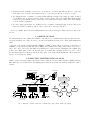
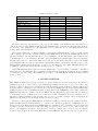
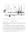
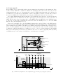
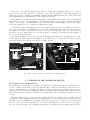
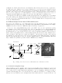
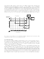
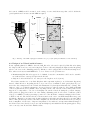
ARAL: a facility to fuel VLTI instruments with photons
Sébastien Morel∗ a , Martin Vanniera , Serge Ménardib , Fabio Biancat-Marchetb ,
Michael D. Fischera , Philippe Gittonb , Andreas Glindemannb , Stéphane Guisarda ,
Nicolás Haddada , Nico Housena , Alexis Huxleyb , Mario Kiekebuscha , Antonio Longinottib ,
Thanh Phan-Ducb , Markus Schöllera , Anders Wallanderb
a European
Southern Observatory, avenida Alonso de Córdova 3107,
Casilla 19001, Vitacura - Santiago, Chile;
b European Southern Observatory, Karl-Schwarzschild-Straße 2,
85748 Garching-bei-München, Germany
ABSTRACT
The ARAL system of the VLTI is a multipurpose facility that helps to have the interferometric instruments ready
for night observations. It consists of an artificial source (allowing a Mach-Zehnder mode of the interferometric
instruments for autotest), an alignment unit (verifying the position of the celestial target in the VLTI field-ofview), and an optical path router (controlling the optical switchyard and the instrument feeding-optics in the
VLTI laboratory). With the multiplication of VLTI instruments and their specific features (wavelength coverage,
number of beams), an upgrade of ARAL (from its November 2002 version) had to be carried out: the alignment
unit has been redesigned, as well as the artificial source. This source will provide a point in the visible and in J,
H, K and N infrared bands, split into four beams (with a zero optical path difference at the reference position).
After a description of the optomechanics and of the computer architecture of ARAL, we detail the difficulties of
building an interferometric artificial source with a wide spectral range.
Keywords: interferometric instruments, optical alignment, artificial source.
1. INTRODUCTION
One difficulty of long baseline interferometry is the complexity and the length of the optical paths. The requirement of Coudé foci for the telescopes, of delay-lines and the possibility to select one (if not a pair) among several
instruments, imply a large number of mirrors, and a narrow field-of-view. Another challenge is the pointing and
tracking accuracies, that are required to overlap the beams inside the instrument. When the celestial object
to be acquired is within the maximum available field-of-view, it should be possible to monitor the position of
the object for each beam. From this information, the telescope pointing can be corrected, in order to bring the
centroid of the object at an optimal position for the instrument.
Moreover, it is important for some instruments to have a daily health check of their intrinsic interferometric
transfer function (fringe contrast for an unresolved source). This monitoring requires an artificial source providing
coherent beams. Such a device can also help to diagnose instrument problems like a failure of the piezo modulator
(used to generate interferograms by scanning the optical path difference – OPD – between the beams).
A modern interferometric facility must also be able to host several instruments, depending on the type of
science to be done. Each instrument has specific features such as spectral range, spectral resolution, number of
beams to be recombined, etc... It is therefore important to be able to seamlessly switch from one instrument
to another one, or to use several instruments at the same time. This implies the use of computer-controlled
motors that can translate and rotate mirrors and dichroics to quickly change the optical path inside the room
(“laboratory”), where the instruments are installed.
The system providing all the above functionalities for the VLTI is called ARAL (ARtificial source and
ALignment unit). It currently consists of:
∗
E-mail: [email protected]
• An interferometric spatially-coherent source, providing two coherent beams with λ from 0.6 to 5 µm, and
in the future four coherent beams with λ from 0.6 to 5 µm, and probably also λ from 8 to 13 µm.
• An “alignment unit”, consisting of a technical CCD (TCCD), sensitive in the visible spectrum, mounted
on a sighting-telescope (refractor) that is aligned on the reference axis of the VLTI. This alignment unit
features an optomechanical system to image any of the VLTI stellar beams, focusing either at the infinity
or at the entrance pupil plane.
• A beam routing system inside the VLTI laboratory, consisting of switchyard mirrors and feeding-optics
mirrors and dichroics. All the positions of these optics can be remotely controlled .
As we see, ARAL offers more functionalities than its acronym would suggest. This comes from “historical”
reasons.
2. ORIGINS OF ARAL
The first instrument of the VLTI, called VINCI,1 was dedicated to commissioning mostly. It featured an interferometric artificial source called “Leonardo”, as well as an alignment checking device called ALIU (ALIgnment
Unit).
Because of the arrival of instruments like AMBER2 or MIDI3 working with more than two beams (three for
AMBER) or in specific wavebands (N-band for MIDI), and requiring new feeding-optics, it has been decided to
remove the control of Leonardo and ALIU from VINCI, and to build a “hidden” instrument called ARAL, that
would control ALIU and Leonardo. At the same time, we realized that a machine would be needed to control
the switchyard (after motorization) and the feeding-optics of the future VLTI instruments. These tasks have
therefore been delegated to ARAL.
3. COMPUTER ARCHITECTURE OF ARAL
ARAL consists of a Unix workstation (waral) and of three LCUs (local control units), which are VME-bus chassis.
Each LCU uses a PowerPC CPU board running under VxWorks (real-time OS) with the VLT LCU common
software.
User workstation or X-terminal
wvgvlti WS (ISS)
waral WS (OS, ICS, DCS)
VLTI instrument
(MIDI, VINCI, AMBER)
OS (operated through BOB)
Network
larics1 LCU (ICS)
larics2 LCU (ICS)
Interferometer
supervisor
software (ISS)
lartccd LCU (DCS)
ARAL ICS
GUI
Photons
Artificial-source
lamps
M
M
ALIU and Artificialsource motors
M
M
ARAL DCS
GUI
ARAL OS
ARAL
ICS
ARAL
DCS
Motors
TCCD
M
Switchyard and
feeding-optics motors
Technical CCD
Fig. 1. Hardware computer architecture of ARAL (left) ; and Software architecture (right).
Table 1. ARAL motor list
Motor name
Switchyard
Artificial source
Alignment unit
MIDI feeding-optics
VINCI feeding-optics
FINITO feeding-optics
AMBER feeding-optics
PRIMA/MIDI laser optics
PRIMA FSU-A feeding optics
IRIS feeding optics
Type
Rotation
Translation
Translation
Rotation
Translation
Rotation
Rotation
Translation
Translation
Translation
Quantity (current)
3
2
3
2
2
3
3
0
0
0
Quantity (future)
8
4
3
2
2
3
3
2
2
3
The LCU called lartccd is dedicated to the control of the TCCD of the alignment unit. The LCU larics1
controls the motors of the alignment unit and of the artificial source, as well as the lamps and the “K-laser”
(see Sect. 6.1) of the artificial source. The third LCU, larics2, controls the motors of the switchyard and of the
feeding-optics of the instruments.
The software architecture of ARAL is similar to any standard VLT instrument,4 based on CCS (central
control software). Its core is the observation software (OS), which is the front end for the VLTI ISS (interferometer
supervisor software). The OS dispatches the received commands to the ICS (instrument control software) and
to the DCS (detector control software). The ICS controls the ARAL motors and the light sources. A part of the
ICS (the low level motor control) runs within larics1 and larics2. The DCS controls the readout of the TCCD
of the alignment unit. It is based on the standard VLT TCCD software, and includes a modified version of the
RTD (real-time display) panel, allowing the operator to set the integration time easily. This RTD includes the
possibility to “pick” in the field-of-view the celestial object to be centered.
Any VLTI instrument that requires action from ARAL has to do it by sending a command to ISS that is
then forwarded to the ARAL OS. These commands are included in the instrument “templates” used for building
observation blocks. The control of the ARAL devices can also be done manually, through the ICS GUI controlled
by the operator.
4. MOTOR CONTROL
Each ARAL mechanical device features a DC motor, an incremental encoder, and a tachometer. For linear (or
translation) motions of optics, Schneeberger (Switzerland) translation stages have been procured. For rotary
motions of optics, we have chosen rotation stages from Newport/Micro-Contrôle (France). The list of the motors
is given by Table 1: currently, a total of 18 motors is controlled by ARAL. Once the 1st generation VLTI facility
is fully integrated, 32 motors (including the future feeding-optics for the PRIMA fringe sensor units,5 and for the
IRIS infrared tip-tilt sensor6 ) will be controlled by ARAL. An extra LCU will be required then. The specifications
of positioning accuracy of ARAL devices are ± 100 µm for a mirror translation along its normal direction, ±
200 µm for a mirror translation along its plane, and ± 5 arcsec for a mirror rotation. These specifications are
fully met by the Schneeberger and Newport stages we have procured.
The motor control system is ESO standard, and has successfully been used in the past on numerous instruments and subsystems at Paranal Observatory: each motor is controlled in position by a VME Maccon board,
and in velocity by an ESO custom-made VME4SA DC servo amplifier board.7 The Maccon board computes in
real-time a velocity order from the actual positioning error given by the position encoder. This velocity order
is sent to the amplifier board which controls the motor current according to the received velocity order and the
actual velocity read from the tachometer. Each Maccon and VME4SA board pair can control up to four motors.
V
U
Trioptics
focus
ARAL
LCUs
Pupil lens
Switchyard
optics
AMBER feeding optics
FINITO
feeding
optics
VINCI feeding-optics
MIDI
feeding
optics
Artificial
source
optics
ALIU
: existing rotation stage
: rotation stage in project
: existing linear stage
: linear stage in project
: other existing motor
incoming beam
(from M16)
Fig. 2. VLTI laboratory layout with the locations of the ARAL-controlled motors. Grey lines: possible routing for the
optical beam SWD-4-I, also known as “beam A” (see Sect. 5.2).
5. THE ALIGNMENT UNIT
5.1. Purpose of ALIU
At the beginning of a VLTI run using the 8.2-m VLT Unit Telescopes (UTs), it is important to check that the
optical path is free. This is done for each beam by switching on a beacon (halogen lamp) located near the
Nasmyth focus of the corresponding telescope, downstream of the M4 mirror. The image of this beacon should
be seen on the ALIU TCCD.
The alignment of instruments like VINCI or AMBER also uses ALIU. By retro-illuminating their fibers, a
spot is seen on the TCCD. It should correspond to the spot from the artificial source. These spots define the
“reference pixels” of the instruments for each beam in autotest. On sky, the reference pixel is defined for each
beam by the center of the field-of-view of the VLTI as seen on the ALIU TCCD, for example by pointing at
the Moon. During the acquisition phase, the centroid of the star image must be moved to the reference pixels.
For each telescope, and from the centroid in the field-of-view of the ALIU TCCD, the measured error vector
is converted into an alt-az offset, in the case of the VLTI with siderostats. In the case of the VLTI with the
UTs, an offset computed from the error vector is applied to the Coudé guider which controls the UT secondary
mirror. These procedures are iterated until the error vector is smaller than a threshold. From the operator side,
the procedures are identical, whether the telescopes for the VLTI are the siderostats or the UTs.
In the case of MIDI, since this instrument has an imaging mode with a small (2 arcsec) but sufficient fieldof-view, the ALIU TCCD is not required for the stellar acquisition procedure.
5.2. Latest upgrade
In the VLTI laboratory, eight parallel stellar beams are running from the switchyard to the instruments. These
beams are named “SWD-x-I” or “SWD-x-S”. SWD means “switchyard” (where these beams come from), ‘x’ is an
identifying number (from 1 to 4), ‘I’ means that the beam feeds a VLTI scientific instrument, and ‘S’ that it feeds
a technical sensor. Commonly, we call SWD-4-I “beam A” and SWD-3-I “beam B” (note that this convention
is reversed for MIDI !). The nominal OPD between any pair of SWD-x-I/S beam is zero (see Sect. 6.1).
The original ARAL alignment unit was installed on the VINCI table and featured an optical setup allowing
image acquisition from two VLTI beams only. The original upgrade plan was designed for a four-beam version of
ALIU. The idea was to place a long linear stage on the MIDI feeding-optics (FO) table of the VLTI laboratory
to “intercept” one among the four instrument beams and feed it into the TCCD (moved to a corner of the MIDI
FO table, along with its sighting-telescope).
However, the possibility to also look at the PRIMA beams was later considered. Therefore, the ALIU upgrade
had to be foreseen for eight beams. This required a 1680-mm range (at least) translation stage. Unfortunately, the
longest translation stage available from Schneeberger (NCB-76 series) had a 1490-mm range, and was therefore
able to check the alignment of seven beams. It has been decided that the beams observable by ARAL would
be SWD-2-I to SWD-4-I and SWD-1-S to SWD-4-S, in order to be able to check the alignment of the PRIMA
fringe sensor units5 (FSUs). In the future, the SWD-1-I beam can be accessible by upgrading ALIU (mounting
a small linear stage on the carriage of the NCB-76 to extend its range, for example).
VINCI
feeding-optics
Retroreflector
Linear stage
(TMF3-100)
for the pupil lens
BS cube on linear stage
(TMF3-100)
Sighting
telescope
Mirrors on linear stage
(NCB-76)
TCCD
VINCI
feeding-optics
BS cube on linear stage
(TMF3-100)
To VINCI
VINCI table
V
Retroreflector
U
Beam A
Beam B
From the telescopes
PRIMA beams
Beam C Beam B Beam A
MIDI
reference plate
SWD-2-I SWD-3-I SWD-4-I SWD-1-S SWD-2-S SWD-3-S SWD-4-S
Linear stage
(TMF3-100)
for the pupil lens
To
MIDI
MIDI feeding-optics table
Sighting
telescope
TCCD
Linear stage (NCB-76)
BS cube
U
Retroreflector
To VINCI, AMBER, PRIMA
V
Fig. 3. ALIU in its original two-beam configuration (top) ; and the proposed upgrade (bottom).
The carriage of the NCB-76 translation stage supports a CaF2 50/50 beamsplitter (BS) cube, as well as a
retro-reflector (corner cube). It is therefore possible, not only to directly visualize a beam coming upstream from
VLTI optics, but also to visualize retro-illuminated instruments, like VINCI, which use fiber optics. This allows
the internal alignment of such instruments on the VLTI reference frame.
The sighting-telescope (taken from the old ALIU) has been manufactured by Trioptics. Its focal length is 300
mm, and its focus can be remotely adjusted by the ARAL ICS. Also, a “pupil lens” (f = 300-mm achromat) is
mounted on the carriage of a 100-mm Schneeberger motorized translation stage (TMF3 series). It can be slid in
front of the sighting-telescope to visualize the VLTI entrance pupil.
The TCCD is coupled to the sighting-telescope via a relay lens that provides a 1.15 magnification. Therefore,
the effective focal length of the sighting-telescope is 345 mm. This TCCD8 has a 290 × 386 pixels resolution
(each pixel has a 22 µm × 22 µm size), and a 24 ē readout noise. The integration time can be set between 10
ms and 30 s. It can continuously be read out, and the frames are displayed on the RTD (real time display) of
the operator’s control workstation.
The upgrade of ALIU to seven beams took place in January 2004 and lasted one week (integration + verification). The most delicate part was the alignment on the VLTI reference beam (defined by removable targets
put on fixed frames). Nevertheless, the system is now fully operative.
TCCD head
Retroreflector (back)
Pupil lens on
linear stage
Beamsplitter
cube
Focus
motor
Sightingtelescope
entrance
Pupil lens on
linear stage
Sighting-telescope (Trioptics)
NCB-76 linear stage
Fig. 4. The new ALIU as it has been integrated in the VLTI laboratory.
6. UPGRADE OF THE ARTIFICIAL SOURCE
6.1. Purpose of the artificial source
An artificial source for an interferometer must be the equivalent of an artificial calibrator star. It should therefore
consist of a unique polychromatic point source which is split into different beams. Each beam from the source
feeds one of the instrument optical inputs. The OPD between the beams from the artificial source is known by
design and is used as a reference for tuning the internal optical OPD of the instrument. In the VLTI laboratory,
right downstream of the switchyard, the OPD between all the SWD beams is nominally zero when crossed by a
‘v’ axis.
The current artificial source corresponds to the original design of Leonardo (Fig. 5), but is now fully controlled
by ARAL. It consists of lamps installed in an integrating sphere (a gold-coated spherical cavity) procured from
LabSphere, Inc. (New Hampshire). The light from the sphere is injected into a single-mode (for the K-band)
fiber. The other end of the fiber is plugged onto the back of a drilled flat mirror, at a position corresponding to
the focus of a parabola mirror. The resulting 18-mm collimated beam (reflected by the drilled mirror) is split by
a CaF2 BS cube. Each beam is then sent to the instrument, either directly (“autotest” mode), or upstream to
the VLTI optics (“autocollimation” mode). In autocollimation mode, retro-reflectors can be installed at various
points in the VLTI optical beam to send the light back to the instrument. This allows, for example, to test the
delay line control. As an option, instead of the single-mode fiber coming from the sphere, a fibered HeNe red
laser (to provide a visible source for visual alignment) or a fibered 2.3-µm K-laser (long-coherence source for
engineering tests with VINCI) can be plugged onto the back of the drilled mirror, as primary sources.
Though autotest is daily used for VINCI for health check (measurement of the splitting ratios of the MONA
fiber beam combiner), autocollimation is used for special engineering tests only. Currently, the Leonardo source
can only be used for two-beam instruments in K-band (i.e., mostly for VINCI). Therefore, its upgrade is necessary
for the new VLTI instruments.
6.2. Different designs for the future VLTI artificial source
The upgrade of the artificial source of the VLTI is still pending. The main difficulty has been to determine which
features would be needed for this source, depending on the requirements for each instrument. For example,
AMBER needs a three-beam source. MIDI may require a N-band (8 to 13 µm) source.
In the case of the existing FINITO fringe-tracker of the VLTI,9 there are some requirements regarding
the polarization of the beams produced by the source. Moreover, using BS cubes for feeding an instrument in
autotest has been proved to be useless (imaging both the source and a stellar object on the ARAL TCCD or on
the instrument is never done), and these BS cubes can be replaced by flat mirrors (having a better reflection for
all the considered wavelengths, and more robust mounting systems). Also, BS cubes for autocollimation can be
replaced by mirrors. These mirrors are designed and adjusted to only reflect the lower half of each beam from
the artificial source. After reflection by corner cubes (located anywhere in the VLTI optical train), each returned
clipped beam would pass just above the edge of its autocollimation mirror to reach the instrument. This would
help to eliminate the polarization problems, critical for FINITO in autocollimation.
To the instruments
BS cube for
autocollimation
OPD=0 here
BS cube
Parabola
Drilled flat
mirror
120
Single-mode
fiber
120
BS cubes for
autotest
(in position)
Lamps
Integrating sphere
V
U
240
From the telescopes
BS cube for
autocollimation
Detail of the fiber plugged onto the back
of the drilled flat mirror
Fig. 5. Drawing of the current “Leonardo” VLTI artificial source. Dimensions are in mm.
6.2.1. Classical beamsplitter design
Using beamsplitters, as in the original Leonardo system, a new design (Fig. 6) has been imagined for a four-beam
artificial source using three beamsplitters. The condition that the OPD between the beams is zero when crossed
by a ‘v’ axis is respected. This design has the disadvantage to rely on beamsplitters, with all the problems of
polarization this may imply. Moreover, for the N-band source, CaF2 cubes would have to be exchanged for ZnSe
plates (see Sect. 6.3). In this case, due to the high refraction index of ZnSe (2.44 at λ = 2.2 µm, and 2.41 at λ = 10
µm), antireflection (AR) coatings are required. However, it is difficult to imagine an AR coating that would
transmit from 0.6 µm (for visible alignment) to 13 µm. Moreover, it is also difficult to elaborate a beamsplitting
coating with a 50/50 reflection-transmission ratio (R/T ) over this spectral range. The option would be to have
two sets of beamsplitters: the existing CaF2 cubes, and the ZnSe BS plates with compensators. One set of
this optics (either CaF2 or ZnSe) would rest on a “cone-groove-plane” kinematic mounts of the artificial source
opto-mechanical setup, while the other set is on-the-shelf temporarily. Hence, it would be possible to manually
switch between the “short wavelengths” mode and the “long wavelengths” mode quickly. Since the usage of the
N-band source is expected to be rare, an automatic or remote switching from the ARAL software is not required.
Light source
N-band
(MM fiber)
To the instruments
OPD=0 between
any pair of beams
along beam axis
BS0
Light source
JHK-bands
(SM fiber)
BS1
120
120
BS2
120
120
120
120
120
120
This distance can
be anything
V
U
120
From the telescopes
Fig. 6. Design of a 4-beam artificial source for the VLTI using beamsplitters. Only the autotest mode is shown here. This
design includes the N-band source (see Sect. 6.3). Dimensions are in mm.
6.2.2. Split pupil design
Due to the problem of finding beamsplitter elements with R/T = 50/50 over a wide spectral range, and due to
the polarization problems that such elements may have, an alternative would be to spatially split the collimated
beam from the source using a mask (Fig. 7, left). In the plane of the mask, the OPD between two rays of any
pair is zero. The optics downstream of this source need to be designed to keep this property up to the parallel
propagation of the beams along −u to the instrument.
The advantage of such an artificial source is indeed the absence of any chromatism problems (that we may
have with beamsplitters). Hence, it is really possible to have a source with a wide spectral range. The current
plan10 would be to have a vertical collimated beam, split into 4 beams with a smaller diameter. This collimated
source would be installed on the Leonardo table. The design (Fig. 7, right) includes extra feeding-optics (that
might be controlled by ARAL) for one of the PRIMA fringe sensor units. An extra breadboard and table would
be required. The current masked primary source project does not include the N-band. Nevertheless, the general
layout might include the N-band artificial source (see Sect. 6.3) for the two beams of MIDI. In this case, the
ZnSe beamsplitter, the ZnSe compensator plate, and the mirror to feed the beam SWD-3-I (corresponding to
the beam A of MIDI) would be mounted on the carriage of a motorized linear stage that could be slid in the
optical path whenever an autotest with MIDI is required.
Beam D
Beam A
Beam B
Beam C
Mask
Collimator
Fiber exit
Fig. 7. Drawing of the VLTI “split-pupil” artificial source project (the principle is illustrated on the left hand).
6.3. Design of an N-band artificial source
It was originally planned for MIDI, to have the CaF2 BS cubes of Leonardo replaced by ZnSe BS cubes (using
the design described in Sect. 6.2.1), and a single-mode fiber for N-band (bringing the light from the integrating
sphere to the focus of the collimating parabola). This fiber could be plugged instead of the K-band single mode
fiber, whenever an autotest with MIDI had to be done. However, some problems arose:
• Manufacturing ZnSe BS cubes appeared to be difficult, because the cements that could be used to assemble
two half-cubes have a strong absorption in the N-band.
• Single-mode fibers in N-band do not exist yet for the length we needed (≈1 m).
The solution was therefore to use ZnSe BS plates with compensation plates (to avoid chromatic dispersion)
instead of ZnSe BS cubes. Regarding the fiber, we procured a set of multimode chalcogenide (As-Se-Te) onemeter fiber bits, transparent for the N-band and manufactured by Amorphous Materials, Inc. (Texas). The
diameter of the core of this fiber is 100 µm. A new problem arose when we wanted to have Diamond E-2000
connectors (standard Leonardo/VINCI connectors) crimped at the ends of the fiber bits to make patchcords. It
happened to be impossible to do it, due to the fragility: the test fiber bits broke during the operation. Anyway,
such a patchcord, plugged in at the focus of the existing collimating parabola of Leonardo, would have yielded
a big spot on MIDI, not really representing a point source. The alternative consists in crimping a fiber bit into
a chuck at each end. The chuck at the fiber exit is mounted at the center of an XYZ manual linear stage, and
the light is collimated by an extra parabola with a different focal length, and then reflected by an extra drilled
mirror. This optical setup would feed the first beamsplitter at 90◦ from the current K-band source (see Fig. 6)
if the beamsplitter 4-beam source design were implemented. Nevertheless, low-temperature filament lamps for
the N-band source have already been procured (from LabSphere) and installed in the integrating sphere. They
can be remotely controlled from the ARAL software.
7. CONCLUSION
We have presented an auxiliary (but a real) instrument that every night serves the scientific instruments of the
VLTI. The diversity of the VLTI instruments, whether they are in operation already, or are under commissioning,
or will be integrated in the future, is a challenge for the evolution of ARAL. Its upgrade (regarding especially
the artificial source functionalities) is still under development, but many plans have already been studied, and
we are now converging towards a realistic solution. We hope that our experience with ARAL will be useful for
the design of any future interferometer: a centralized facility like ARAL, that can be controlled by any scientific
instrument seems mandatory to have an efficient interferometer.
ACKNOWLEDGMENTS
We thank Volker Heinz and Erich Bugueño at Paranal Observatory, as well as the team of the mechanics workshop
at La Silla Observatory, for having helped us to realize some parts of the ARAL upgrade. We are grateful to
Koen Engels (student at Technische Hogeschool Rijswijk, The Netherlands) for having made some drawings of
these parts. We also thank Cristián Herrera and Andrés Zarate (telescope and VLTI operators), for their help
during the integration of the new alignment unit.
REFERENCES
1. P. Kervella, V. Coudé du Foresto, A. Glindemann, and R. Hofmann, “VINCI: the VLT Interferometer
commissioning instrument,” in Interferometry for Optical Astronomy II, P. J. Léna and A. Quirrenbach,
ed., Proc. SPIE 4006, pp. 31–42, 2000.
2. R. Petrov, F. Malbet, G. Weigelt, F. Lisi, P. Puget, P. Antonelli, U. Beckmann, S. Lagarde, E. Lecoarer,
S. Robbe-Dubois, G. Duvert, S. Gennari, A. Chelli, M. Dugué, K. Rousselet-Perraut, M. Vannier, and D.
Mourard, “Using the near infrared VLTI instrument AMBER,” in Interferometry for Optical Astronomy II,
W. A. Traub, ed., Proc. SPIE 4838, pp. 924–933, 2003.
3. Ch. Leinert, U. Graser, L. B. F. M. Waters, G. Perrin, W. Jaffe, B. Lopez, F. Przygodda, O. Chesneau,
P. Schuller, A. Glazenborg, B. Grimm, W. Laun, S. Ligori, J. Meisner, K. Wagner, E. Bakker, B. Cotton,
J. de Jong, R. J. Mathar, U. Neumann, and C. Storz, “Ten-micron instrument MIDI: getting ready for
observations on the VLTI,” in Interferometry for Optical Astronomy II, W. A. Traub, ed., Proc. SPIE
4838, pp. 893–904, 2003.
4. A. Wallander, J. Argomedo, P. Ballester, B. Bauvir, M. Comin, R. Donaldson, P. Duhoux, A. Gennai,
B. Gilli, N. Housen, A. Huxley, R. Karban, M. Kiekebusch, A. Longinotti, I. Muñoz, and T. Phan-Duc,
“Status of VLTI control system: how to make an optical interferometer a data producing facility,” in
Advanced Telescope and Instrumentation Control Software II, H. Lewis, ed., Proc. SPIE 4848, pp. 95–106,
2002.
5. F. Cassaing, C. Coudrain, B. Fleury, P. Madec, A. Glindemann, S. Lévèque, “Optimized fringe tracker for
the VLTI/PRIMA instrument,” in Interferometry for Optical Astronomy II, P. J. Léna and A. Quirrenbach,
eds., Proc. SPIE 4006, 2000.
6. P. Gitton, S. Lévèque, G. Avila , “IRIS: an infrared tip-tilt sensor for the VLTI,” in New Frontiers in Stellar
Interferometry, W. A. Traub, ed., Proc. SPIE 5491, 2004.
7. B. Gustafsson, CCS-LCU servo amplifier driver user manual. ESO, 2001. VLT-MAN-ESO-17210-0361 - v.
1.4.
8. M. Cullum, Technical CCD systems, operation manual. ESO, 2001. VLT-MAN-ESO-11700-1775 - v. 2.1.
9. M. Gai, B. Bauvir, D. Bonino, L. Corcione, M. Dimmler, G. Massone, S. Ménardi, F. Reynaud, A. Wallander,
“FINITO: the VLTI fringe tracker,” in New Frontiers in Stellar Interferometry, W. A. Traub, ed., Proc.
SPIE 5491, 2004.
10. S. Ménardi, “Technical specification for the JHK beam generator of ARAL/Leonardo,” tech. rep., ESO,
2004. VLT-SPE-ESO-15444-3219.