1
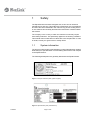
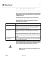
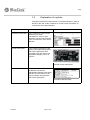
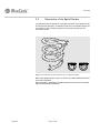
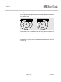
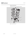
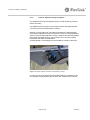
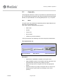
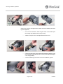
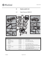
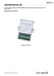
Created by EBCCW 00:06
96:05
Created by EBCCW 00:06
5478EN-3
Spiral Elevator
Type 5995512
User Manual
Original Instructions 2011
Created by EBCCW 00:06
96:05
Created by EBCCW 00:06
Spiral Elevator
User Manual
© Flexlink Components AB 2010
All Rights Reserved
No part of this program and manual may be used, reproduced, stored or
transmitted in any form or by any means without the written permission of
FlexLink Components AB. The contents of this manual are for informational
use only. All information and specifications contained in this document
have been carefully checked to the best efforts of FlexLink Components
AB, and are believed to be true and accurate as of time of publishing.
However, due to continued efforts in product development FlexLink
Components AB reserves the right to modify products and its manuals
without notice.
FlexLink Components AB assumes no responsibility or liability on any
errors or inaccuracies in this program or documentation. Any kind of
material damages or other indirect consequences resulting from any
FlexLink Components AB product part, documentation discrepancies and
errors or non-anticipated program behavior are limited to the value of
appropriate products purchased from FlexLink Components AB. The
products are delivered to the customer at the ’as is’ state and revision level
they are on the moment of purchasing, and are declared in detail in the
license agreements between FlexLink Components AB and user. User
accepts and is obliged to follow the guidelines stated in the separate
license agreement needed in using any parts of this product package.
5478EN-3
5478EN-3
Created by EBCCW 00:06
Content
1
Safety ....................................................... 3
5.2
Assembly ................................................29
1.1
System information.................................. 3
5.3
Validation ................................................33
1.2
The most important safety conditions ...... 4
5.4
Integration in a (transport) system .........35
1.3
Description of safety provisions ............... 5
5.5
Setting of the Spiral Elevator...................37
1.4
Safety measures to be taken .................... 6
5.6
Test run - partially loaded........................39
1.5
Explanation of symbols ............................ 7
6
Technical maintenance ............................43
2
Technical specifications............................ 8
6.1
Check and control procedures ................43
2.1
Technical data........................................... 9
6.2
Maintenance procedures.........................47
2.2
Ordering information.............................. 10
6.3
Troubleshooting list ................................57
2.3
Operating conditions .............................. 11
6.4
Maintenance schedule Spiral Elevator.....60
3
Introduction ........................................... 12
7
Put out of commission............................62
3.1
Purpose of use ....................................... 12
7.1
Disconnect the power sources ................62
3.2
Description of the Spiral Elevator ........... 13
7.2
Disassemble............................................62
3.3
Working principle ................................... 19
7.3
Transport ................................................63
3.4
Control units .......................................... 21
7.4
Disposal ..................................................64
4
Unload the Spiral Elevator ...................... 22
7.5
Reuse......................................................64
4.1
Preparation............................................. 22
8
Spare parts list........................................65
4.2
Unloading instructions ........................... 23
8.1
Spiral Elevator 5995512..........................65
5
Mounting, installation, adjustment ......... 27
9
Supplier’s information.............................66
5.1
Provisions to be provided ...................... 27
10
Manufacturer’s declaration......................67
5478EN-3
Page I of II
Page II of II
5478EN-3
Preface
Purpose of this manual
The purpose of this manual is to describe various operations that are
intended for the user to perform.
This document contains remarks that point out a risky or specific situation
to the user. In many cases this situation is provided with one of the symbols
given below.
General warning for danger!
.
Warning for electrical voltage!
.
Attention, this is an important notice!
.
Compliance with the operations described in this document is important in
order to prevent dangerous situations and unnecessary damage to
the Spiral Elevator
It is recommended to keep one copy of this manual near the machine and
one copy with your technical documentation.
Structure of the manual
Created by EBCCW 00:06
The user's manual has been composed in such a way, that a number
of operations can quickly and easily be found.
This manual does not describe operations that are not intended for the user
to perform.
The user's manual has been divided into sections which describe a variety
of functions including the safety and the safe operation of the
Spiral Elevator.
It is recommended that this manual is read by all users of this equipment
with particular reference to Section 1 on page 3: Safety.
5478EN-3
Page 1 of 68
Requirements of the user
The Spiral Elevator should only be operated by a person who has become
acquainted with section 1 'safety' and trained in the use of the unit.
The Spiral Elevator should only be installed by persons who have become
acquainted with section 4 'unload the Spiral Elevator.
.
.
Note! Maintenance activities on the Spiral Elevator should only
be carried out by a technically qualified person.
Note! Technically qualified employees means: persons that have
received adequate training for carrying out the activities involved.
Page 2 of 68
5478EN-3
Safety
1
Safety
The Spiral Elevator has been designed such, that it can be used and
maintained in a safe way. This holds for the application, the circumstances
and the instructions described in the manual. Any person working with or
on this machine should study and follow the instructions contained within
this manual.
The company or the country in which the machine is used may require
extra safety measures. This particularly applies to the working conditions.
This manual does not describe how these are to be complied with. In case
of doubt, consult your government or safety officer!
1.1
System information
The project number and/or general drawing number (identification number)
shall always be specified when communicating with FlexLink with respect
to the Spiral Elevator.
The following detail plates are generally attached to the Spiral Elevator.
Created by EBCCW 00:06
Figure 1 Example of Machine plate (system supplier)
Figure 2 Spiral Elevator plate ( Manufacturer)
5478EN-3
Page 3 of 68
Safety
1.2
The most important safety conditions
Before the Spiral Elevator is put in to service, the following safety
conditions must be met:
•
Provide good ambient lighting.
•
Equipment users should have read and understood the operating
instructions to operate, maintain or clean the machine.
•
Equipment users should not reach into the machine while it is
running. Even if the machine is not running, it may be 'on', which
means it may start operating automatically.
•
Safety provisions (where fitted), such as side plating, bottom
plating, emergency stops and detectors must not be removed or
deactivated while the Spiral Elevator is running.
•
Before clearing of any jams, the unit should be stopped and safely
isolated.
Page 4 of 68
5478EN-3
Safety
1.3
Description of safety provisions
As a standard the Spiral Elevator is not provided with control or any safety
provisions. Before putting the Spiral Elevator into service some safety
provisions are to be incorporated. The purpose of these safety provisions
is to protect the user, the product and the Spiral Elevator against undesired
situations (damage). If these safety provisions are not incorporated it will
invalidate the warranty.
The table below gives a general description of the safety provisions
required. Only technically qualified persons should work on the settings of
the safety provisions!
The safety provisions listed in the table are a general guide only. The actual
safety provisions to be used must be determined by relevant risk
assessment of the overall system.
Control
Remark
Emergency stop switch
Each Spiral Elevator is to be provided with one or more emergency stop
switches that can be operated within reach of the user. The emergency
stop switch must make sure that the input and output conveyors or
machines are switched off simultaneously.
Motor protection
The technical specification of the Spiral Elevator is, among other things,
geared to the load given in the technical specification, quotation or
drawing.
Should the Spiral Elevator (gear motor) become overloaded, this should be
detected by the motor protection in the control system. Without this
protection there is a chance that the gear motor or other components of the
Spiral Elevator will be damaged and this damage will not be covered by the
warranty.
Motor isolation
Means of isolating the motor from the power supply must be provided and
within close proximity to the motor.
Where the possibility exists for oversize product to enter the Spiral Elevator
it is recommended to install a detector prior to the Spiral Elevator and use
this to stop the elevator thus preventing damage from occurring.
Created by EBCCW 00:06
Note! If an oversize product jams in the Spiral Elevator it may
damage the unit.
5478EN-3
Page 5 of 68
Safety
Mechanical
Remark
Height / width
detector
Product entering the Spiral Elevator should not be of a size where the product
can become jammed in the Spiral Elevator.
In order to ensure that product cannot become jammed in the Spiral Elevator
due to oversize some automatic checks for width and height can be done.
This detection must take place before the Spiral Elevator in order to stop the
product or Spiral Elevator.
The maximum dimensions of the product are given in the technical
specification, quotation or drawing.
Transition guard
The basic Spiral Elevator is not supplied with any guarding at the drive / idler
ends. A risk assessment should be conducted with consideration to the
adjacent conveyors/equipment product etc. to establish any requirements for
guarding.
Note! Only technically qualified persons are allowed to change
the settings of the safety provisions.
.
1.4
Safety measures to be taken
For a safe operation of the Spiral Elevator a number of safety measures are
to be taken. These include the following measures:
•
Clean floor surface - With a clean floor surface the operator will
not be hindered while operating the Spiral Elevator. This can
prevent tripping or slipping, so that the operator does not
unexpectedly come into contact with the Spiral Elevator.
•
Hearing protection -Different tests have shown that the
Spiral Elevator does not produce more than 85dB(A)
Page 6 of 68
5478EN-3
Safety
1.5
Explanation of symbols
Pictogram symbols have been placed on the Spiral Elevator in order to
identify to the user certain conditions or provide certain information on
components of the Spiral Elevator.
No.
Description
Picture
1.Spiral Elevator plate
This contains the name and the
address of the initial
manufacturer, series or type
indication, serial number and the
year of construction of the Spiral
Elevator.
2.Gear motor plate
This contains information of the
gear motor supplier along with the
CE-mark if appropriate. Also
indicated is the gear motor type,
applicable voltages, power, oil
type etc.
Example of Gear motor plate
3. Machine plate
This contains the system supplier,
installation date and the
Identification Number of the Spiral
Elevator and information of the
system supplier along with the
CE-mark if appropriate.
Created by EBCCW 00:06
Example of Machine plate
5478EN-3
Page 7 of 68
Technical specifications
2
Technical specifications
Below is the technical specification of the Spiral Elevator.
Further product details to which the Spiral Elevator has been designed are
contained within the overall Project Documentation (when purchased as
part of a Project System).
Use of the Spiral Elevator outside of the scope detailed within the technical
specification, quotation or documentation will invalidate the warranty.
General FlexLink Spiral Elevator specification
•
500 mm inclination per winding (9 degree)
•
3-8 windings
•
1000 mm nominal centreline diameter
•
Speed 5 - 60 metres per minute
•
Lower height:- 600, 700, 800, 900 or 1000 mm
-
Adjustable -50/+70 mm
•
Max load 10 Kg/m (specific Spiral Elevators may be with a lower
limit due to actual gear motor used)
•
Product size:
-
width= 50 - 200 mm
-
length= 80 - 250 mm
-
height= 1,5 x Length (max 300 mm)
-
see Project Documentation if applicable
•
Drive and idler ends are horizontal
•
Chain width 100 mm
•
Friction top chain
•
Steel chain with bearings running on the inner guide rail
•
Wet coated mild steel frame
•
Column diameter 160 mm
•
M8 thread for guide rail
Page 8 of 68
5478EN-3
Technical specifications
2.1
Technical data
500 mm
(inclination)
5000 mm
(Max. heigth
8 windings)
Lower height
600/700/800/900/1000 mm -50/+70
Machine incl.
adjustable feet
5°
8x45°
350
815
In/ Out Feed Configurations
n159
985
Created by EBCCW 00:06
1000
5478EN-3
Page 9 of 68
A
B
Technical specifications
2.2
Ordering information
Example of a Spiral Elevator designation obtained from the FlexLink
product configurator:
Item no A
B
C
D E F
G
H I
5995512 100 - 1000 - 500 - S - A -TU - 800 - 3 - 25
5995512- Item number
A
Chain width
B
Spiral center of chain diameter
C
Incline per winding
D
Mild steel (S) material configuration
E
Configuration A or B
F
Transport direction up/down TU or TD
G
Lower height 600/700/800/900/1000
H
Number of windings 3,4,5,6,7,8
I
Shaft diameter 20 mm (for gear motor type SA37) or 25 mm (for
gear motor type SA47)
For more information please contact your local FlexLink office.
Page 10 of 68
5478EN-3
Technical specifications
2.3
Operating conditions
The circumstances under which the Spiral Elevator can be operated partly
depend on the materials selected. FlexLink has defined a number of
parameters within which the Spiral Elevator would be allowed to function.
Should the Spiral Elevator still be operated beyond these limiting values,
FlexLink cannot guarantee the good functioning of the Spiral Elevator.
Ambient temperature (in operation)
0 to +35°C
During transport / storage
5 to +40°C
Relative air humidity (RH)
30% to 95%, not condensing
Lighting
Normal ambient lighting
Height
Up to max. 2000 m above sea
level
As a standard no lighting is installed on the Spiral Elevator although this
can not be added as an option. Normal ambient lighting is sufficient to work
safely with the Spiral Elevator. The Spiral Elevator is not intended for use
in an open air environment or in an area with a risk of explosion, although
static safe materials are available.
Created by EBCCW 00:06
If in doubt of the suitability FlexLink should be consulted.
5478EN-3
Page 11 of 68
Introduction
3
Introduction
This section deals with a number of general matters with respect to
the Spiral Elevator. This involves, among other things, the purpose of use,
the conditions of use and the working principle of the Spiral Elevator.
Should you have any further questions on the safe operation of the
Spiral Elevator please contact FlexLink.
The warranty conditions have been included in the FlexLink quotation or
are available separately from FlexLink.
FlexLink does not accept any liability for unsafe situations, accidents and
damages resulting from:
•
Neglect of warnings or stipulations as displayed on the machine,
in this documentation or in the Project Documentation
(if applicable).
•
Use in applications or circumstances other than those specified in
this manual, the quotation, the Project documentation
(if applicable), or FlexLink catalogue.
•
Modifications to the machine. This also includes the use of
replacement parts other than those specified and supplied by
FlexLink.
•
Insufficient or incorrect maintenance.
FlexLink does not accept any liability for the consequential damage in case
of failures of the machine, for example damage of products, interruption of
operation, etc.
3.1
Purpose of use
The purpose of use of the Spiral Elevator is to transport products / goods
in a vertical direction. This may be for bridging a difference in height or for
functioning as a cooling buffer.
It is not recommended to use the Spiral Elevator for transporting products
with parts that are protruding, hanging loose, for transporting products that
result in a higher load than mentioned in the documentation or for
transporting products with measurements deviating from those given in the
technical specification associated with the particular Spiral Elevator.
Additionally it is not permitted to walk, stand or sit on the Spiral Elevator or
to stick objects or body parts between the guards, conveyor plates or other
moving parts.
Page 12 of 68
5478EN-3
Introduction
3.2
Description of the Spiral Elevator
The Spiral Elevator is applied in a (transport) system where products can
be transported vertically in a relatively small area. The Spiral Elevator can
be coupled to other transport systems and be built according to the
customer's needs.
A
B
Figure 3 Principle sketch (Transport direction up) / Configuration options
Created by EBCCW 00:06
Before the Spiral Elevator is put in to service a suitable Risk Assessment
should be completed.
After integration / installation the Spiral Elevator should not be relocated
without further Risk Assessment
5478EN-3
Page 13 of 68
Introduction
Configuration input / output
The configuration of the Spiral Elevator is available in different formats with
regard to input / output positions. These configuration types are expressed
in the letters A or B.
A
B
It is possible to have a configuration with which the output side is placed at
a different angle. For any special configurations please contact FlexLink.
Dimensions of the Spiral Elevator
The height of the Spiral Elevator is dependant upon the low level height
plus the number of turns of the spiral (see Technical Specification - Section
2 on page 8).
Page 14 of 68
5478EN-3
Introduction
Components Spiral Elevator
The Spiral Elevator consists of the following components:
1
2
3
4
5
Created by EBCCW 00:06
Figure 4 Components Spiral elevator
5478EN-3
Page 15 of 68
Introduction
No.
Component
Description
1, 2, 4
and 5
Frame
The basic frame of the Spiral Elevator consists of a central column (1), an
upper end (2), a lower end (5) and a frame (4) that is attached to the floor
surface. The materials of these components depend on the configuration
selected. Both the upper end and the lower end may function as the input or
output part of the Spiral Elevator.
3.
Conveyor
chain (slats)
The conveyor chain consists of a chain and conveyor chain / plates with guide
rollers. The top of the chain has a high friction material to ensure no sliding of
products on the chain. The conveyor chain rotates in a spiral form around the
central cylinder and is guided on the plastic slide strips. The conveyor chain is
driven by the gear motor.
Gear motor
The gear motor is mounted on the drive shaft of the conveyor drive end.
The standard Spiral elevator is not delivered with a gear motor. However a
gear motor may be added as part of the supply contract.
Suggested Gear motor specifications can be obtained from the FlexLink
Configurator or from FlexLink.
The gear motor requires a Torque arm kit and a Absorber kit to prevent rotation
and two types are available as follows:
•
For SA37 type gear motors, Torque arm kit = 5057039
-
•
Absorber kit = 5113736
For SA47 type gear motors Torque arm kit = 5050459
-
Absorber kit = 5113736
On the driving shaft a sprocket wheel has been mounted that is connected to
the chain of the conveyor chain.
Guide rail,
optional
The guide rail ensures that the products follow the conveyor chain and prevent
them from falling off the Spiral Elevator.
Spiral elevator (typically as
delivered)
Lower end
Page 16 of 68
Upper end
5478EN-3
Introduction
General terminology used for the Spiral Elevator parts
Central column
A
B
Lower end unit
B
6
Upper end unit
1
2
3
4
5
7
8
6
1
Metal chain or
transmission
chain
2
3
7
Slide rail
4
Sprocket or
Sprocket wheel
Base frame
Created by EBCCW 00:06
Feet
5478EN-3
Bearing for
conveyor chain
Link
Conveyor
A
8
Conveyor
chain plate,
link or slat
Page 17 of 68
5
Sprocket or
Sprocket wheel
Bearing housing
with bearing
Introduction
4
3
1
2
1) Conveyor plate
1) Motor
2) Basic chain
2) Drive shaft
3) Link
3) Sprocket wheel
4) Bearing
4) Torque arm
Components conveyor chain
No.
Component
Description
1.
Conveyor chain plate
(slat)
Narrow plastic plate provided with a guide roller. Conveyor plates are
mounted in a row on the basic chain and so form the transport
surface.
2.
Metal chain
(transmission chain)
This is a laterally flexible chain on which the conveyor chain is
mounted.
3.
Link
Links of the Metal chain (item 2)
4.
Bearing
Bearing for the conveyor chain plate
Components conveyor drive end and gear motor
No.
Components
Description
1.
Gear motor
Optional
2.
Drive shaft
_
3.
Sprocket wheel
_
4.
Toque arm
Type specific dependant upon gear motor type
Page 18 of 68
5478EN-3
Introduction
3.3
Working principle
The purpose of the Spiral Elevator is to transport products / goods vertically
to bridge a difference of height.
2
1
5
3
4
Created by EBCCW 00:06
Figure 5 Principle sketch Spiral elevator
5478EN-3
1
Conveyor chain
2
Upper end
3
Lower end
4
Return part
5
Gear motor (not shown)
Page 19 of 68
Introduction
In most cases the Spiral Elevator is integrated in to a system. The input /
output side of the Spiral Elevator is determined dependent on the system.
In the following example, it is assumed that the input is at the lower end of
the Spiral Elevator and that the product will bridge a difference in height in
order to continue the required transport on the output.
Input end
Transport of Products
Output end
1
The product is transferred onto the input of the Spiral Elevator.
The gear motor drives the conveyor chain with the required
speed.
2
Subsequently, the product on the conveyor chain will travel
around the Spiral Elevator and bridge the height difference
between input and output.
3
When the product arrives at the output of the Spiral Elevator it will
continue along the system. The conveyor chain returns in the
underside of the Spiral Elevator to the input position.
Page 20 of 68
5478EN-3
Introduction
3.4
Control units
As a standard the Spiral Elevator is delivered without any control system.
When a Spiral Elevator is supplied without control it is the responsibility of
the system integrator / installer to design a suitable control system.
It is preferable to install an isolating switch for the gear motor and it should
be of a type able to be padlock off.With this switch the power to the gear
motor can be switched / locked off in order to ensure safe working on the
Spiral Elevator.
The designer of the Control System should evaluate the requirements of
other devices such as Emergency stops etc. in order to provide a safe
working system.
Created by EBCCW 00:06
Figure 6 Example of a Isolator
5478EN-3
Page 21 of 68
Unload the Spiral Elevator
4
Unload the Spiral Elevator
4.1
Preparation
Before starting the unloading, good preparation is required.
The appropriate devices must be available.
A series of checks must be made to the Spiral Elevator and these should
be done:
•
Before off-loading from the delivery vehicle.
•
Immediately after off-loading.
•
Immediately after unpacking.
Any damage must be detailed on the delivery note before signing for
acceptance of delivery and also notified to FlexLink in order to possibly
progress any warranty claim.
Details of the dimensions and technical specifications are available on one
or more of the following:
•
Technical specification
•
Quotation
•
Drawing
•
Order
Any deviation must be notified to FlexLink immediately.
Page 22 of 68
5478EN-3
Unload the Spiral Elevator
4.2
Unloading instructions
Initially the Spiral Elevator should be removed from the delivery vehicle by
lifting the Spiral Elevator complete with any pallet base and / or packing
materials.
Before starting unloading, all fastening means (securing belts, screws, etc.)
that secure the Spiral Elevator onto the transport vehicle must be removed.
It is preferable to move the Spiral Elevator complete with any pallet base
and / or packing materials to an area near to the final position and then
unload the spiral elevator and place it directly on the floor whilst taking care
not to cause any damage to the painted surfaces.
The Spiral Elevator may be delivered horizontally or vertically dependent
on the dimensions.
If the Spiral Elevator is delivered vertically it can be lifted using a ForkLift
truck under the base frame or by using a sling and suitable eye bolt in the
top of the central column.
Created by EBCCW 00:06
If the Spiral Elevator is delivered horizontally, it can be lifted using a ForkLift
truck with forks spaced wide apart and inserted under the horizontal central
column. Soft packing should be used between the forks and the central
column to avoid damage and marking. Care must be taken to avoid the
Spiral Elevator rolling whilst on the forks. Alternatively slings can be used
and attached to two positions around the central column.
5478EN-3
Page 23 of 68
Unload the Spiral Elevator
4.2.1
Erecting the Spiral Elevator
This section is for taller Spiral Elevators which are transported in the
horizontal position.
When putting the unit upright or when moving the Spiral Elevator make
sure that the floor is level and clean and has sufficient load carrying
capacity.
It is generally safer to move the Spiral Elevator to a position close to the
final area with the Spiral Elevator remaining on the delivery packing (where
applicable).
When the Spiral Elevator is near to the final position it can be put upright.
Dependent on the situation, the Spiral Elevator can be raised to upright
using a hoist, a crane or a forklift truck.
Device(s)
Hoist Crane
.
Open-end spanner
Note! Make sure when raising to upright, that there is enough
space / height to put the Spiral Elevator upright.
Page 24 of 68
5478EN-3
Unload the Spiral Elevator
The following describes a typical method utilizing a hoist
•
The hoisting device is to be fastened to the cylinder at the top of
the Spiral Elevator. Whilst hoisting, the hoist should be well fixed
and must not be able to ride/shift away unexpectedly.
•
Raise the top of the Spiral Elevator around 200mm and stop.
•
Remove the frame with feet which is temporarily mounted to the
Spiral Elevator column top.
•
Raise the Spiral Elevator until lifted completely from the floor and
in the vertical position. Take care not to put excessive side load on
the feet to avoid bending or damaging them
Note! Be aware that the Spiral Elevator may tip at the moment it
is near to the upright position. Make sure there are no persons
near the Spiral Elevator!
.
Created by EBCCW 00:06
•
5478EN-3
Remove feet from the now horizontal position and re-fit in to the
other holes in the frame to have the feet in the vertical position.
Page 25 of 68
Unload the Spiral Elevator
.
.
.
•
Re-attach the frame with feet, to the final position at the bottom of
the Spiral Elevator column. Attach the stay brackets between the
Spiral Elevator column and the bottom frames.
•
Remove feet from the now horizontal position and re-fit in to the
other holes in the frame to have the feet in the vertical position.
•
Check all bolts for the lower frames, feet and stay brackets are in
place and secure.
•
Lower the Spiral Elevator down on to the floor.
•
Move the Spiral Elevator in to final position taking care not to place
undue side load on the feet to avoid damage. If the Spiral Elevator
is moved using a ForkLift truck or Pallet Truck, great care must be
taken due to the height of the Spiral Elevator to ensure that it does
not topple over.
•
The feet can be adjusted to give the correct height. Make sure all
four feet are adjusted evenly.
Note! Carry out these operations calmly in order to be able to
carefully monitor any movement of the Spiral Elevator.
Warning: It is forbidden to walk under the Spiral Elevator
duringthe procedure of rising to the upright position.
Note! Make sure that while raising the Spiral Elevator that there
are no unauthorised persons near the Spiral Elevator.
Page 26 of 68
5478EN-3
Mounting, installation, adjustment
5
Mounting, installation, adjustment
This section deals with the installation and adjustments for the
Spiral Elevator.
The safety conditions detailed in section 1.2 and the Safety Provisions
detailed in section 1.3 should be read and understood before installation.
5.1
Provisions to be provided
Make sure before integrating that the safety measures detailed in section
1.4 are taken.
5.1.1
Floor construction
During installation / integration a number of items must be considered
including the suitability of the floor and how the unit is fixed to the floor.
Created by EBCCW 00:06
Tools (typical)
5478EN-3
•
After having placed the Spiral Elevator in the correct position, the
Spiral Elevator should be set to the correct height and the column
must be vertical.
•
Following this the feet should be fastened to the floor surface by
using the holes in the adjusting feet.
•
Fasteners suitable for the type of floor / mounting surface should
be used.
Page 27 of 68
Mounting, installation, adjustment
5.1.2
Links to adjacent conveyor systems
Any additional bracing of the Spiral Elevator in-feed should be provided
where necessary.
Any additional bracing of the conveyor/process after the Spiral Elevator
out-feed should be provided where necessary.
With the correct heights set, the distances between the Spiral Elevator
ends and the adjacent conveyors / machines can be set. The gap between
spiral conveyor end and adjacent conveyor / machine should not be greater
than 25mm and depends upon various factors such as product being
transferred and safety considerations.
A sliding bridge or roller bridge may be needed for transfer of products.
Figure 7 Example of typical connection to an adjoining conveyor
If conveyors are to be attached to the Spiral Elevator it is possible to use
the specially designed joining pieces which are available from FlexLink.
Page 28 of 68
5478EN-3
Mounting, installation, adjustment
5.2
Assembly
This paragraph describes a number of operations for Spiral Elevators that
are not delivered fully assembled. After having finished mounting the Spiral
Elevator, the Spiral Elevator can be integrated (Section 1.4) in a system.
5.2.1
Motor
The gear motor may be delivered separately with the Spiral Elevator and
then has to be mounted on site.
First check if all the required parts are present:
•
Gear motor
•
Grease
•
Torque arm
•
Key for shaft
•
Fasteners (screw and washer)
The key and torque arm fastening to the frame may be pre-assembled.
The required tools are:
Open-end spanner
Ring spanner
Internal spring pliers
Created by EBCCW 00:06
Procedure:
5478EN-3
•
Determine the installation orientation of the gear motor.
•
Apply installation grease on the shaft to slide the gear motor onto
the shaft easier and prevent any fretting corrosion.
•
Attach the torque arm to the gear motor with the appropriate
fixings.
•
Place the locking ring (circlip) in the gear motor or move to the
desired groove in gear motor (if not already in the correct
position).
Page 29 of 68
Mounting, installation, adjustment
(Note: The conveyor and gear motor shown are not necessarily the same
type as supplied.)
•
In the correct orientation, slide the gear motor on the shaft up till
the locking ring (aligning the keyway to key).
•
Attach the torque arm to the Spiral Elevator drive end.
•
Fasten the shaft to the motor with bolt and washer inside the gear
motor hollow shaft and place the cover to protect the opening (if
cover is applicable).
•
Check all fastenings and remove excess installation grease.
Page 30 of 68
5478EN-3
Mounting, installation, adjustment
5.2.2
Mounting Guide rail components
The basic Spiral Elevator does not include guide rail or brackets. Along the
sides of the conveyor track are M8 tapped holes typically every 45º to allow
brackets to be attached.
The following describes how a typical FlexLink Guide Rail Bracket system
can be used on the Spiral Elevator.
For final detail of the optimum guide rail and bracket arrangement consult
the Spiral Elevator supplier or FlexLink.
Tools
Typical Guide Rail and bracket components
4
5
3
2
6
1
Note!
Created by EBCCW 00:06
Guide rail components (typical)
1
Guide rail bracket
2
Guide rail clamp support
3
Guide rail clamp
4
Guide rail
5
Guide rail cover
6
Distance piece
Note! Grind or cut off the small lugs on the FlexLink guide rail bracket
(or distance piece) before assembly.
5478EN-3
Page 31 of 68
Mounting, installation, adjustment
Procedure for fitting a typical guide rail
Attach the Guide Rail Brackets to the frame.
If an offset has been chosen, any distance piece has to be placed between
the frame and the Guide Rail Bracket.
The bolts used to attach the brackets to the conveyor sides should be M8.
The length of bolt depends upon the guide rail bracket arrangement used,
but should not protrude in to the beam profile by more than 10mm.
With the brackets in place, the guide rail profile can be mounted to the
brackets and clamps.
Figure 8 Connection mounting bracket
If the guide rail is to be FlexLink polyethylene, XLRS 3x15 P type then to
ensure rigidity at the ends it is suggested to pre-bend a 150 mm long and
10x10 mm metal bar or an Ø10 mm metal rod to the radius of the guide rail
and insert it in the guide rail at each end.
Make sure that there is a smooth connection between the guide rail joints,
to ensure product passes along the guide rail un-hindered.
Page 32 of 68
5478EN-3
Mounting, installation, adjustment
5.3
Validation
Initially the validation checks should be for visual condition and
dimensions.
Subsequently a short test run should be made with the Spiral Elevator in an
un-loaded condition.
5.3.1
Dimension check Spiral Elevator
The technical specification and / or relevant drawing can be used for the
dimension check.
5.3.2
Adjusting and setting the Spiral Elevator
Before the start of the test run make visual checks for jammed parts or
items touching the Spiral Elevator chain links and stop immediately if any
exist.
During the test run pay attention to the correct rotation direction of the
conveyor chain and look at the behaviour of the conveyor chain and the
operation of the drive. The chain should move evenly and without undue
jerking motions.
It is not recommended to make a test run with the machine while the safety
provisions have been deactivated or guards removed. Make sure that the
operation is as safe as possible and that there are no unauthorised persons
near the Spiral Elevator.
If during the test run abnormal sounds are heard or if there is an impression
that other irregularities occur, immediately switch off the Spiral Elevator
then investigate and remedy the cause. The checklist in section 5.6 and the
troubleshooting list in section 6.3 may be of assistance.
If the problem cannot be solved, please contact the supplier for advice
before continuing the integration.
Created by EBCCW 00:06
If the initial test above is OK, then the following test procedure may be
followed.
5478EN-3
Page 33 of 68
Mounting, installation, adjustment
Test Procedure
No.
Test
Checks
Duration
1.
Run the Spiral Elevator
for very short duration
(at 10 Hz if variable
speed motor).
Check the Spiral Elevator for the
rotation direction of the conveyor
chain. If this is not correct, then make
necessary adjustments to the
electrical control circuit or system.
2.
Run the Spiral Elevator
(run at 10 Hz if variable
speed motor).
Check whether the conveyor chain
plates have been mounted correctly
the conveyor chain and the plates
run evenly over the slide rail.
Carried out
Yes / No
10
minutes
Yes / No
Check whether the chain runs
smoothly and without any significant
noises. Should there be any
problems, refer to the
troubleshooting list in Section 6.3.
3.
Run the Spiral Elevator
at 25 Hz (if variable
speed motor).
Repeat the checks in item 2 above.
10
minutes
Yes / No
4.
Let the Spiral Elevator
run at the nominal speed
described in the
technical specification or
detailed within the
quotation.
Check for peculiar sounds or
unusual movements of components.
10
minutes
Yes / No
5.
.
Check whether the chain runs
smoothly and without any significant
noises. Should there be any
problems, refer to the
troubleshooting list in Section 6.3.
If all of the items above have been complete and the Spiral Elevator runs
satisfactorily, then the remaining parts of the overall system can be checked
and the overall subsequently run.
Yes / No
Warning: It is not recommended to make a test run with the
machine while safety provisions have been deactivated or guards
removed.
Page 34 of 68
5478EN-3
Mounting, installation, adjustment
5.4
Integration in a (transport) system
The Spiral Elevator is a machine that is integrated in a system of
conveyors. This means that an input and output are to be connected to it.
If the Spiral Elevator is to be fitted into an existing situation, this usually
gives more problems with the installation than in a completely new
situation.
5.4.1
Frequency control
The operating conditions are optimal when the speed of the Spiral Elevator
is equal to the speeds of the in-feed and out-feed conveyors or machines.
If a speed difference does exist this can lead to product twisting at the
transfers and wear of the high friction conveyor plates.
If there are speed differences which are unavoidable, these should be kept
bellow 15% and the preferred arrangement is as follows:
•
Spiral Elevator up to 15% faster than in-feed conveyor or machine
speed.
•
Out-feed conveyor or machine speed to be up to 15% faster than
Spiral Elevator.
The speeds can be tuned by using a frequency controller within the control
system if desired.
If a frequency controller is used for the speed control, ramp-up and rampdown settings should be set such that the Spiral Elevator chain does not
'snatch' or 'jerk' on starting or stopping.
Created by EBCCW 00:06
.
5478EN-3
Note! For the correct setting of the frequency controller the
technical specification supplied with the unit should be followed.
Page 35 of 68
Mounting, installation, adjustment
5.4.2
Checklist integration
After the integration the checklist given below should be completed to
ensure a satisfactory integration.
No.
Component
Remark
Checked
1.
Lower end
Is the lower end at the correct height and is the distance to the
adjacent conveyor / machine satisfactory (should be below
25mm and suitable for other considerations regarding product
transfer and safety)?
Yes / No
For correct height refer to technical specification, quotation
details or drawings.
2.
Upper end
Is the upper end at the correct height and is the distance to the
adjacent conveyor / machine satisfactory (should be below
25mm and suitable for other considerations regarding product
transfer and safety)?
Yes / No
For correct height refer to technical specification, quotation
details or drawings.
3.
Spiral Elevator
Is there sufficient space around the Spiral Elevator to allow
adequate access for operation, and maintenance?
Yes / No
4.
Fastening /
foundation
Is the Spiral Elevator fixed to the floor satisfactorily and is the
central column vertical?
Yes / No
Page 36 of 68
5478EN-3
Mounting, installation, adjustment
5.5
Setting of the Spiral Elevator
The mechanical and control setting for the Spiral Elevator need to be done
correctly, with particular regard to the ends and transfers to ensure good
operation.
5.5.1
Mechanical
Mechanically there are a number of items which can be set for the Spiral
Elevator. The general items are detailed below .
Tools
No.
Component
Setting / Remark
1.
Height setting Spiral Elevator
The adjusting feet can be used to set the Spiral Elevator
to the correct height. If necessary, the connecting
conveyors should be adjusted to this as well.
It is not possible to change the difference in height
between the lower and upper ends after the Spiral
Elevator has been manufactured (i.e. the pitch between
turns are fixed).
2.
Guide rail, input and output
(optional)
The guide rail width setting may be able to be adjusted at
infeed and outfeed ends of the Spiral Elevator in order to
align with the feeding and receiving conveyor systems.
This may depend upon which guide rail and brackets are
fitted.
Created by EBCCW 00:06
It may be possible to 'flare out' the guide rails at the in-feed
end of the Spiral Elevator
5478EN-3
Page 37 of 68
Mounting, installation, adjustment
5.5.2
Controls
The table below gives some general guidelines with regard to the control
system used to operate the Spiral Elevator. .
No.
Component
Setting
Remark
1.
Frequency control
(where fitted)
15%
The speed difference of the feeding conveyor to the
Spiral Elevator or the Spiral Elevator to the receiving
conveyor should generally be below the setting value.
This is to avoid product twisting at the transfers and
excessive slipping of the product on the conveyor or
Spiral Elevator chain.
2.
Emergency stop switch
Direct
The Spiral Elevator should be protected via an
emergency stop circuit, such that if the relevant
emergency stop button (or other) is activated, all power
is removed from the Spiral Elevator gear motor,
following which the Spiral Elevator may overrun a little
(depending upon speed).
The full details of the emergency stop circuit and
procedure must be evaluated by the persons
responsible for designing the control system.
3.a.
Start / Stop via 'Direct on
Line' control
<3 sec.
The conveyor will start almost immediately and will stop
and overrun a little (depending upon speed).
3.b.
Start / Stop via
Frequency controller
(Inverter)
2 sec.
For normal conditions the ramp-up and ramp-down
time set in the frequency controller should be set to 2
seconds.
4.
Height / width detector
Direct
Where over height or over width detection is
incorporated, the stopping of the conveyor should be
activated immediately with the stopping times
suggested in the above items.
Page 38 of 68
5478EN-3
Mounting, installation, adjustment
5.6
Test run - partially loaded
In this paragraph the Spiral Elevator will be checked in a semi-loaded
condition with all safety provisions activated. If during the test run any of
the following situations occur, the test must be stopped and the
Spiral Elevator must not be tested further until the issue has been solved.
•
Irregular sounds
•
Other irregularities / anomalies
•
Spiral Elevator does not meet specifications
•
Some of the product do not fit on the Spiral Elevator
•
Product become stuck or slip
Carry out the check
Initially start the Spiral Elevator with no product loaded and conduct the
items in the checklist.
Then gradually add product to the system up to 50% of the specified feed
rate as detailed in the technical specification or quotations and conduct the
items in the checklist again.
The gradually add more product to the system up to 100% of the specified
feed rate as detailed in the technical specification or quotations and
conduct the items in the checklist again.
If during any of the tests problems are detected, the Spiral Elevator must
be stopped and the problem investigated / remedied and then the tests
restarted.
Check Spiral Elevator
Below is the checklist detailing the main items to check on the
Spiral Elevator when making the test runs.
Created by EBCCW 00:06
Checklist
No.
Check
Remarks
Passed
1.
Does excessive noise occur?
This may occur because the tension of the
chain is not correct, conveyor plates are loose
or a sprocket wheel is not aligned (see Section
6.3 on page 57).
Yes / No
2.
Is a 'ticking' sound is
present?
This may occur because the tension of the
chain is not correct, conveyor plates are loose
or a sprocket wheel is not aligned (see Section
6.3 on page 57).
Yes / No
5478EN-3
Page 39 of 68
Mounting, installation, adjustment
No.
Check
Remarks
Passed
3.
Are any conveyor chain
plates moving unexpectedly
at any position throughout
the Spiral Elevator?
This may occur if there are some loose
conveyor plates (see Section 6.3 on page 57).
Yes / No
4.
Are there any conveyor chain
plates which are raised at
any position?
This may occur because conveyor plates are
loose or the reversing rollers or a sprocket
wheel are not aligned well (see Section 6.3 on
page 57).
Yes / No
5.
Are there any damaged
conveyor chain plates or is
there friction material
missing?
If any are detected the conveyor chain plates
concerned are to be replaced (see Section
6.2.2 on page 48).
Yes / No
6.
Are conveyor chain plates
touching the frame, the
guide, the guard or anything
else?
Adjust the guide or the guard and carefully
check the correct setting / dimension of this.
See 'technical specification', quotation or
drawing for any relevant settings.
Yes / No
7.
Do all products fit on the
conveyor chain?
Check in the technical specification, quotation
or drawing whether the product dimensions are
correct to those specified.
Yes / No
8.
Do any products slide off of
the conveyor chain?
Are the conditions, sizes and weights of the
products correct to the technical specification,
quotation or drawing?
Yes / No
Is there any 'foreign substance' on the product
or conveyor chain reducing the effect of the
friction material?
Generally the sliding of products should not
occur, therefore contact the supplier.
9.
10.
Are there any products that
do not continue over the
transfer on to or off of the
Spiral Elevator.
Check the condition of the transfers.
Is the product arriving on to
and transferring off of the
Spiral Elevator correctly
oriented?
The design of the adjoining equipment should
be checked.
Yes / No
Any transfers supplied as part of the system are
in addition to the standard Spiral Elevator and
generally these transfers are not powered,
therefore some product may remain on the
transfer (depending upon various factors such
as speeds, condition, size or weight of product).
Page 40 of 68
Yes / No
5478EN-3
Created by EBCCW 00:06
Mounting, installation, adjustment
No.
Check
Remarks
Passed
11.
Is the product properly
transported throughout the
Spiral Elevator.
Generally the product will not twist whilst
travelling up or down the Spiral Elevator. If
undue twisting does occur, discuss this with the
supplier.
Yes / No
12.
Are there any protrusions or
irregularities along the guide
rail?
The product should not stick or jam against the
guide rail.
Yes / No
5478EN-3
Page 41 of 68
Mounting, installation, adjustment
Check (safety) provisions
The basic Spiral Elevator supplied by FlexLink does not include any
additional safety provisions such as isolators, stop/start devices,
emergency stopping systems or guards at the in-feed / out-feed ends.
Any issues with regard to the safety items should be investigated and
discussed with the designer of the control and safety system.
Below is a check list for some general safety items.
No.
Check
Remarks
Passed
1.
Does the stop button stop the
Spiral Elevator within the time
expected.
Both the Spiral Elevator and the input/output
chain should stop immediately within the time
dictated in the 'technical specification',
control design specification or within 3
seconds depending upon speed.
Yes / No
2.
Does the Spiral Elevator stop
when the emergency stop is
pressed.
The Spiral Elevator should stop immediately
and this should be less than 3 seconds
depending upon speed.
Yes / No
3.
Does the optional height / width
indicator function when
processing a product which is too
large.
The height / width detector should react when
a product is coming by that is larger than the
specified product mentioned in the 'technical
specification' or quotation.
Yes / No
Should the (safety) provisions not function as expected, they should be set
or adjusted again or repaired by the person responsible
(installer / technician).
Page 42 of 68
5478EN-3
Technical maintenance
6
Technical maintenance
Technical maintenance is an important part of this manual.
Good maintenance will prolong the life of the Spiral Elevator and help to
reduce any costs resulting from breakages or downtime.
This section includes a troubleshooting list in section 6.3 and a
maintenance schedule in section 6.4.
Before any maintenance functions are carried out on the Spiral Elevator the
power supply to the gear motor must be safely isolated.
6.1
Check and control procedures
6.1.1
Checking conveyor plates
As a result of products becoming jammed the conveyor plates may partly
break off or be pushed from the conveyor chain.
If missing or broken conveyor plates are detected, these are to be
replaced.
Figure 9 Conveyor plate broken
Created by EBCCW 00:06
Dirt or product labels sticking to the conveyor plates may also make the
plates break or become loose. It is therefore strongly recommended to
regularly check and clean the Spiral Elevator.
5478EN-3
Page 43 of 68
Technical maintenance
6.1.2
Checking chain tension and chain stretch
The conveyor chain of the Spiral Elevator must have the correct tension.
If the tension is not correct, the following may occur:
•
Chain runs off the sprocket (jumps a cog).
•
Conveyor plates grab into the return track causing them to break
or become loose from the chain.
•
Excessive wear of the end sprocket caused by too high tension.
In order to prevent these problems, it is necessary to regularly check the
chain tension. This can be done by following the procedure below.
Procedure to check chain tension
•
Make sure that the main switch has been switched off, and safely
isolated.
•
Measure/mark a 500mm section of the conveyor chain near to the
lower end. Then compress and stretch this 500mm section of the
conveyor chain and measure the variation in the length.
•
If this variation is more than 38.5 mm (1.52") this indicates that at
least one conveyor link can be removed from the chain. On the
side of the conveyor there may be a graduated scale with up to
38mm indicated in green and above 38mm indicated in red and
this scale can be used to gauge the variation in length.
Figure 10 Distance check
.
Note! If you are not sure whether the conveyor chain is to be
shortened or not, please contact the supplier of the Spiral
Elevator.
Page 44 of 68
5478EN-3
Technical maintenance
Procedure to check chain stretch
•
Make sure that the main switch has been switched off, and safely
isolated.
•
At a position on the idler or drive end of the Spiral Elevator, stretch
at least 8 conveyor chain plate links apart.
•
Measure the distance between the start of plate 1 and the start of
slat 8 (i.e. the pitch across 7 conveyor chain plates - see picture).
For a new chain this distance is 267 mm [10,5"].
•
The maximum allowed chain stretch is 1.5%.
•
Therefore the metal chain must be replaced when the measured
distance is more than 271 mm [10,67"].
•
Refer to section 8 for spare part numbers and contact FlexLink to
procure the necessary parts.
Nominal 267 mm, Maximum 271 mm
Figure 11 Tape measure on conveyor chain
Created by EBCCW 00:06
.
5478EN-3
Note! If more than 1.5% of the original number of conveyor chain
plate links have been removed to correct chain tension, then this
indicates that the overall chain is in need of replacement..
Page 45 of 68
Technical maintenance
6.1.3
Checking guide rail
Products that are transported over the Spiral Elevator can make contact
with the guide rail. A stoppage may damage the guide rail. This may later
result in products getting stuck at the damaged place and therefore it is
important that the guide rail is regularly checked for irregularities and is
adjusted or repaired if necessary.
6.1.4
Checking for products sliding
One of the conditions that apply to the Spiral Elevator is that products being
transported should not slide.
Conveyor plates have high friction material to avoid this.
Therefore it should be checked regularly whether sliding does or does not
occur.
Any observed sliding may have different causes, which can include the
following:
.
•
Worn high friction conveyor which will need to be replaced with
new.
•
Products are transported that are not described in the technical
specification. If this is the case the end user is expected to contact
the supplier of the Spiral Elevator.
•
Foreign matter is on the friction conveyor or on the product. This
foreign matter must be removed.
Note! If the sliding cannot be remedied, please contact the
supplier of the Spiral Elevator.
Page 46 of 68
5478EN-3
Technical maintenance
6.2
Maintenance procedures
It's strongly recommended to perform maintenance activities according to
the methods described. During maintenance proper and safe tools must be
used. Before disassembling any part please refer to the assembly section
in this manual.
6.2.1
To move the conveyor chain
Follow the below procedure to move the conveyor chain within the Spiral
Elevator:
.
Created by EBCCW 00:06
.
5478EN-3
1
Ensure that the Spiral Elevator is free of products
2
Make sure that the main switch has been switched off, and safely
isolated.
3
Release the brake if present on the gear motor so the chain can
move freely.
4
Depending upon the ratio of the gear motor it may be necessary
to remove the gear motor.
5
Check the conveyor chain moves in the Spiral Elevator smoothly.
Note! If the rotation feels very heavy it's possible that the
conveyor chain is jamming somewhere. Check the conveyor
chain and remove any possible obstruction. Make sure the brake
is released.
Danger: Make sure that the main switch has been switched off,
and safely isolated, in order that there is no possibility that the
spiral elevator can be started unexpectedly.
Page 47 of 68
Technical maintenance
6.2.2
Replacing conveyor plates(slats)
This paragraph explains how to replace a broken or missing conveyor plate
(slat).
Note! If a conveyor plate is incorrectly mounted damage to the
Spiral Elevator and the products transported on it may result.
.
Danger: Make sure that the main switch has been switched off,
and safely isolated.
.
Follow the below procedure to replace a conveyor plate (slat):
•
The slat can be replaced best at the lower end of the
Spiral Elevator.
•
The slat is clicked onto a connection link with two lugs underneath
and can be removed from the chain by spreading these lugs. Pull
back on both tips of the slat while keeping your thumbs pressed
on the centre of the slat. The slat lugs will now be spread so that
it can be pulled from the chain see Fig. 10. Repeat this procedure
if more than one slat needs to be removed.
Figure 12 Removing a slat
•
New slats can now be placed on the metal chain. Make sure that
the slat is always placed on the connecting links of the chain and
that the bearing on the slat is placed on the column side of the
track. Pull back on both tips of the slat while keeping your thumbs
pressed on the centre of the slat. The slat lugs will now be spread
so the slat can be placed on the chain (see Fig. 11).
Page 48 of 68
5478EN-3
Technical maintenance
•
Apply force on the middle of the slat so that it clicks onto the chain.
You can possibly use a rubber mallet for this. Repeat this
procedure if more than one slat needs to be placed.
Figure 13 Placing a slat
•
.
.
.
.
Created by EBCCW 00:06
.
5478EN-3
After maintenance on the conveyor chain test run the machine at
10% of the speed and check if the conveyor chain runs correctly.
Note! Make sure that the slat is always placed on the connecting
links of the chain and that the bearing on the slat is placed on the
column side of the track.
Note! Each 5 metre of chain is connected by two connecting
links. To locate these links the slats above them are marked with
red dots. Make sure that the correct slats are placed back onto
the chain, possibly marking them.
Note! The flaps on the underside of the conveyor chain (slats)
are suited for one time use only. Disassembly of the conveyor
chain from the metal chain can cause damage to the flaps and
therefore it is not recommended to re-use conveyor chain links
(slats).
Note! If a conveyor plate is replaced because a plate is missing,
the chain tension should also be checked.
Note! If the Spiral Elevator has been provided with bottom
plating, one should check for remainders of conveyor plates. If
these are found, the bottom plating is to be removed in order to
remove these parts.
Page 49 of 68
Technical maintenance
6.2.3
Shorten chain
If the conveyor chain stretch exceeds the limit (see Section 6.1.2 on page
44) the chain must be shortened.
Shortening the chain can best be done at the lower end. FlexLink delivers
a chain tensioner with the machine to assist in this procedure.
Procedure to shorten the chain:
Figure 14 Working room at lower end
•
Every 5 m [16' 5"] the metal chain is connected with 2 connecting
links. The slats located above these links are marked with two red
dots. The chain can easily be shortened by removing one of these
two connecting links.
•
Create access to the metal chain by removing the conveyor slats
with the red dot plus several conveyor slats either side. The slats
are removed when in the position at the end of the lower end unit.
The procedure for slat removal is detailed in section 6.2.2. The
conveyor chain will need to be moved around to access the slats
and the procedure for this is detailed in section 6.2.1
•
First remove the security locks from both connecting links. Once
these have been removed the gold coloured plates and the
connecting link can be removed.
•
Now place the chain tensioner if available at both loose ends of
the chain and turn it until both ends meet see Fig. 13.
•
Place back one connecting link (including the security lock) and
the chain is then shortened. Fig. 14 shows what parts are taken
out of the belt.
•
Return the chain back to the service location and place the new
slats back on the chain. Make sure you place a marked slat over
the connecting link.
•
If the metal chain is still too long, repeat this procedure at another
location which still has two connecting links. At least one
connecting link must remain at each relevant location.
Figure 15 Tensioning the chain
Page 50 of 68
Figure 16 What remains!
5478EN-3
Technical maintenance
6.2.4
Align sprocket wheel
If the conveyor chain does not run smoothly or is noisy, one of the sprocket
wheels at the conveyor ends may not be aligned correctly. This may cause
extra wear of chain and sprocket wheel.
Tools
Procedure to align sprocket wheel at lower or upper end
Created by EBCCW 00:06
Figure 17 Lower end
5478EN-3
•
Move the conveyor plate with the coloured dot to the lower or
upper end. Remove several of the conveyor plates (slats), so that
when the link is removed from the chain the sprocket wheel is
released.
•
The sprocket wheel has been locked to the shaft with an Allen
screw. By loosening this, the wheel can be moved to the left or to
the right.
•
When the wheel has been aligned correctly, the chain can be
connected again by means of the locking link and subsequently
the conveyor plates can be replaced again. Make sure that a
conveyor plate with a coloured dot is put on to the correct position
of the locking link.
Figure 18 Upper end
Page 51 of 68
Figure 19 Allen screw
Technical maintenance
6.2.5
Replace sprocket wheel, upper end
Find the conveyor plate with a coloured dot marked on it and move this
conveyor plate to the upper end of the Spiral Elevator. Under this conveyor
plate there is a locking link that can easily be removed.
Tools
Danger: Make sure that the main switch has been switched off,
and safely isolated.
.
Procedure
Figure 20 Dismounting of bolt
•
Remove the conveyor plate with the coloured dot. Under this
conveyor plate there is a locking link and the metal chain can be
separated here. The sprocket wheel is now released from the
chain.
•
The gear motor should be dismounted from the shaft. This is done
by removing the bolt mounted in the hollow shaft of the gear motor
and after this the bolt that is connecting the torque arm with the
Spiral Elevator should be loosened. The gear motor can then be
removed.
Figure 21 Bolts torque arm
Page 52 of 68
Figure 22 Motor removed
5478EN-3
Technical maintenance
•
Once the gear motor has been removed, the grub screw in the
locking rings of the bearing blocks can be loosened. The bearing
blocks can then be removed and slid off of the ends of the shaft.
•
The shaft with sprocket wheel can then be removed from the end
unit.
Figure 23 Bearing block with locking
Figure 24 Shaft with sprocket wheel ring
Note! The shaft and sprocket are removed as one piece. These
can be replaced as one piece or as individual items. If replaced
as individual items make note of the orientation of the sprocket
wheel on the shaft.
Created by EBCCW 00:06
.
5478EN-3
•
Re-fitting is the reverse procedure of the removal.
•
After assembly the Spiral Elevator must be set up (section 5.3.2)
and then test run (section 5.6) to check that all items are
satisfactory.
•
After approval the Spiral Elevator may be put into operation again.
Page 53 of 68
Technical maintenance
6.2.6
Replace sprocket wheel, lower end
Find the conveyor plate with a coloured dot marked on it and move this
conveyor plate to the lower end of the spiral conveyor. Under this conveyor
plate there is a locking link that can easily be removed.
Tools
Danger: Make sure that the main switch has been switched off,
and safely isolated
.
Procedure
•
Figure 25 Dismounting of slide rails
Remove the conveyor plate with the coloured dot. Under this
conveyor plate there is a locking link and the metal chain can be
separated here. The sprocket wheel is now released from the
chain.
Figure 26 Dismounting of shaft
Figure 27 sprocket wheel
released from chain
•
Remove the slide rails to allow necessary space for subsequently
remove shaft and wheel (see Fig. 23.).
•
Loosen the central screw on each side of the shaft at the lower
end (see Fig. 24).
•
When the screws are removed, the shaft with the sprocket wheel
can be lifted / slid out.
Page 54 of 68
5478EN-3
Technical maintenance
Note! The shaft and sprocket are removed as one piece. These
can be replaced as one piece or as individual items. If replaced
as individual items make note of the orientation of the sprocket
wheel on the shaft.
Created by EBCCW 00:06
.
5478EN-3
•
Re-fitting is the reverse procedure of the removal.
•
After assembly the spiral elevator must be set up (section 5.3.2)
and then test run (section 5.6) to check that all items are
satisfactory.
•
After approval the Spiral Elevator may be put into operation again.
Page 55 of 68
Technical maintenance
6.2.7
Lubricate the motor
The lubrication of the Spiral Elevator gear motor should lead to a
continuous good functioning of the machine. The oil level of the motor is to
be checked regularly.
•
For details of the oil type see the motor specification plate or the
documentation from the supplier of the Spiral Elevator or the
supplier of the gear motor.
•
For details of the oil fill quantity and oil level refer to the gear motor
manufacturer.
•
For details of the routine maintenance frequencies etc. refer to the
gear motor manufacturer.
Figure 28 Typical gearbox breather (vent)
.
Note! For details of the maintenance and lubrication contact gear
motor manufacturer.
Page 56 of 68
5478EN-3
Technical maintenance
6.3
No.
Trouble
Possible cause
Solution
1.
Spiral Elevator
does not work
No power (volts) at the gear motor
The cause for lack of
power to be
investigated by
qualified personnel.
Gear motor defective
Replace the motor
Teeth on the sprocket wheel worn
Replace the sprocket
wheel.
2.
Created by EBCCW 00:06
3.
5478EN-3
Troubleshooting list
Spiral Elevator
does not work, but
the motor is
running
Conveyor plates
broken or
misaligned
It is recommended to
replace the entire chain
at the same time.
The metal chain is not located on the
sprocket
Realign the sprocket
and investigate the
cause.
Product jamming the Spiral Elevator
Remove the product
jam and check the width
/ height detectors (if
fitted).
Product weight overload / too much
product or weight on the Spiral
Elevator
Remove product and
operate within the
specification limits.
Metal chain broken
Repair or replace the
metal chain and check
sprockets.
Product jamming the Spiral Elevator
Remove the product
jam and check the width
/ height detectors (if
fitted).
Irregularities in the guide strips
Repair or replace the
relevant guide strip.
Foreign objects / material on conveyor
chain
Remove the foreign
objects or materials.
Chain too long, which makes the
plates grab at the entry to the
underside return guide
Shorten the chain (see
Section 6.2.3 on page
50).
Page 57 of 68
Technical maintenance
No.
Trouble
Possible cause
Solution
4.
Product stops as a
result of defective
conveyor plates
Missing or defective conveyor plate.
Replace conveyor plate
(see Section 6.2 on
page 47).
5.
Product stops at
beginning or end of
Spiral Elevator
Product orientation
Check cause of
products incorrect
orientation.
Defective transition roller arrangement
(if fitted)
Contact the supplier of
the FlexLink Spiral
Elevator.
The product is pushed to the outside,
because there is no space between
the products on the Spiral Elevator.
The feed rate of the
product is too high for
the Spiral Elevator
speed. Check to see if /
why the feed rate is
above the specification
or why the Spiral
Elevator speed is below
the specification.
Typically the products
should have a minimum
distance between of
25% of the product
length.
Poor alignment of the products
Align the product before
the Spiral Elevator.
Guide rails not set correctly
Set guide rails to correct
height.
Product height is too low for guide rail
Check if product is to
specification or contact
the supplier.
Combination of speed and continuous
load of product stoppage
Shorten the chain (see
Section 6.2.3 on page
50)
6.
7.
Product jams
under guide rail
Chain too long
Page 58 of 68
5478EN-3
Technical maintenance
No.
Trouble
Possible cause
Solution
8.
Transfer of product
on to or off of spiral
elevator is poor
(depending upon
product &
specification, the
actual transfer may
vary).
Product stoppage
Repair the transfer unit
if faulty
Product load too high
Check the technical
specification for the
maximum product
weight and contact the
supplier.
Transfer unit not aligned correctly.
Align the transfer unit.
Transfer unit dirty
Clean the transfer unit.
Torque arm locked too tightly, which
may cause torsion between shaft and
motor shaft hole e
Replace the seal and
look whether the
mounting causes the
problem.
Gear motor becoming too hot due to
overload
Check cause of
overload and remove.
Replace gear motor or
seal
Sprocket wheel not aligned
Align sprocket wheel
Chain tension
Check the chain tension
and shorten the chain if
necessary
Broken conveyor plate
Check the conveyor
chain and replace the
broken plate
9.
10.
Created by EBCCW 00:06
.
5478EN-3
Oil leaking on the
seal between drive
shaft and motor
Noise level from
the spiral elevator
is above normal
Note! Always remove the broken conveyor plate and loose plate
material before replacing the missing strip.
Page 59 of 68
Technical maintenance
6.4
Maintenance schedule Spiral Elevator
The FlexLink Spiral Elevator generally requires relatively little
maintenance.
The list below details the general maintenance operations which must be
carried out at the normal time intervals for those maintenance operations.
The maintenance intervals are for a Spiral Elevator operating in normal
conditions with single shift working (8 hours per day) and in a normal
environment.
For more working hours or for an environment which has more dirt or
abrasive particles around or on the Spiral Elevator, the end user must
decide upon the appropriate maintenance intervals taking in to account all
of the conditions.
To achieve good working life from the Spiral Elevator the various
maintenance items must be done correctly and at the correct time intervals.
Only replacement parts detailed within the recommended spare parts
listing detailed in section 8 should be used. The use of other parts which
are not detailed within the spare parts listing will invalidate the warranty.
For any warranty issues for the Spiral Elevator, all of the maintenance
operations and times must be fully documented and kept in a suitable
maintenance log or the warranty will be void.
Page 60 of 68
5478EN-3
Technical maintenance
Maintenance schedule Spiral Elevator
No.
Execution
Interval
Remark
1.
Clean conveyor
Monthly
Regular cleaning depends on
product and environment
2.
Check the conveyor chain for
broken or missing conveyor
plates, replace if necessary
Daily
It is the task of the operator to
check this daily (see user’s
manual)
3.
Check the chain tension
Monthly
Remove a link if the chain is 38.5
mm too long. If more than two
links at the same time are to be
removed, contact the supplier.
4.
Check the sprocket wheel
and alignment. Replace or
align if necessary
Monthly
Faulty alignment of the sprocket
may cause permanent wear or
make the chain derail and can so
cause serious stoppages.
5.
Check the guide rails for
dents, damages and
connection
Monthly
Replace guide pieces if they
damage the products to be
transported. If the cause is bad
guide rail, contact the supplier.
6.
Clean inside below ends
Monthly
Accessible dirt will accumulate at
the bottom side.
7.
Check the drive for oil
leakage and undue noise
Monthly
Repair or replace if necessary.
See the troubleshooting list
8.
Check whether the Motor is
fastened well to the Spiral
Elevator. Tighten the bolts if
necessary
Monthly
Drive vibrations can make the
bolts loosen, then faulty alignment
of the drive can bend the shaft
and the chain may derail.
9.
Check the oil level in the
Motor, fill up if necessary
Monthly
Take a look at the gear motor
specifications of the manufacturer
10.
Change the oil in the Gear
motor
In accordance with the gear motor specifications of the
manufacturer
Created by EBCCW 00:06
.
5478EN-3
Note! Make sure that the main switch has been switched off, and
safely isolated.
Page 61 of 68
Put out of commission
7
Put out of commission
Decommissioning should be undertaken in a safe and controlled manner.
This section details the items which must be done for this
decommissioning.
7.1
Disconnect the power sources
The main power isolator must be turned off and 'locked off' or power
permanently removed from the isolator. If the isolator is mounted on the
Spiral Elevator the power supply must be permanently removed from the
isolator.
This is to ensure that there can be no electrical supply to the gear motor
connections either before or after the gear motor is removed.
Danger: First switch off the main switch before the power source
may be disconnected.
.
7.2
Disassemble
While dismounting the machine, the regulations for waste processing
applicable for the country and local authorities at the time of the dismantling
are to be complied with.
The machine only contains commonly known materials.
At the time of assembly and delivery of the Spiral Elevator there were
processing possibilities for these materials and no particular risks were
known for persons involved in the dismantling process.
The disassembly of the Spiral Elevator generally requires few operations.
Depending upon the height of the Spiral Elevator it may be required to lay
the Spiral Elevator horizontal. If this is necessary the procedure for this is
generally the reverse of the procedure used to stand up the elevator
detailed in section 4.
.
Note! At the time of assembling the Spiral Elevator there were
processing possibilities for the various materials within the unit
and no particular risks were known for persons involved in the
dismantling process.
Page 62 of 68
5478EN-3
Put out of commission
7.3
Transport
While transporting the Spiral Elevator a number of safety measures are to
be taken.
Use the same tools and equipment as indicated in section 4 for the Unload
of the Spiral Elevator.
A suitable Method Statement and Risk Assessment for the dismantling and
transportation should be done by the relevant responsible person. This
Method Statement should be followed throughout the decommissioning
process.
.
Created by EBCCW 00:06
.
5478EN-3
Note! A transport frame / base should be used which is similar to
the unit used for the initial delivery of the Spiral
Note! Transport of the Spiral Elevator in the vertical or horizontal
mode depends upon the access route, vehicle height and general
height of the Spiral Elevator.
As a guide, all Spiral Elevators with a total height above 2.4
metres should be transported in the horizontal mode.
Page 63 of 68
Put out of commission
7.4
Disposal
If the Spiral Elevator is to be disposed of, then all current regulations for the
country and local authorities must be adhered to.
The main materials within the spiral elevator can vary depending upon the
design of the Spiral Elevator and any accessories attached to the
Spiral Elevator (such as guide rail parts). The following lists the general
materials within the Spiral Elevator but is not a total list:
7.5
•
Steel (various grades)
•
Stainless steel
•
Plastic
•
Hardened steel (e.g. bearings and transmission (metal) chain)
•
Aluminium
•
Polyamide
•
Polyethylene
•
Oil / grease in bearings, transmission (metal) chain and gear
motor
•
Materials within the gear motor
Reuse
If the Spiral Elevator is to be re-used for another application, then full details
must be checked to establish whether the Spiral Elevator is suitable for this
new application.
Clarification for the new application should be sought from the original
Spiral Elevator supplier or FlexLink (there may be a charge for this service).
A full Risk Assessment will need to be completed for the use in the new
application before the Spiral Elevator can be put in to service.
.
Note! Putting the Spiral Elevator out of commission or in to a new
use must only be carried out by technically qualified personnel.
Page 64 of 68
5478EN-3
Spare parts list
A 10
8
Spare parts list
8.1
Spiral Elevator 5995512
B
6
B
2
1
3
4
10
5
7
8
9
9
1
2
7
6
3
4
5
8
9
10
Created by EBCCW 00:06
9
A
Item
1
2
3
4
5
6
Description
Chain link
Bearing
Connection link
Sprocket wheel
Bearing
Chain
Part No
5112485
5112486
5112487
5112488
5112489
5112491
Qty
1
1
1
1
1
1
7
Slide rail
5112492
1
8
Sprocket wheel
5112493
1
9
Guides
5116179
1
10
Guide
5117173
2
5478EN-3
10
Comments
TPS1-MF-R PP
Kit of 20 pcs
3/4” steel, Kit of 5 pcs
3/4” 19T for shaft 30mm
3/4” Side flexing L=5m
Kit contains 20 meter slide rail 24x18
single ditch SV with pins and 3 mm drill bit
3/4” 19T for shaft 20 mm
Kit containing guides left/right, pins, drill bit
and assembly instruction
Single guide, order 2 pcs for each end
Page 65 of 68
Supplier’s information
9
Supplier’s information
This document was drawn up by:
FlexLink Components AB
Date: 2010/08/23
Copyright: FlexLink Sweden, 2010
The machine was produced/ supplied by:
Flexlink Components AB
Tel: +46 (0)31-337 31 00
SE-415 50 Göteborg
Fax: +46 (0)31-337 31 95
Sweden
E-mail: [email protected]
www.flexlink.com
and
Local FlexLink Systems supplier
.
Note! In case of failures please contact the system integrator.
Page 66 of 68
5478EN-3
Manufacturer’s declaration
10
Manufacturer’s declaration
The Spiral Elevator is supplied to be incorporated within an overall
transport system and is not intended to be used as a stand alone piece of
equipment.
Therefore a Certificate of Incorporation is applicable for the unit.
Created by EBCCW 00:06
Any Certificate of Incorporation will be contained within the separate
documentation supplied with the Spiral Elevator or overall system.
5478EN-3
Page 67 of 68
Manufacturer’s declaration
Page 68 of 68
5478EN-3