1
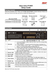
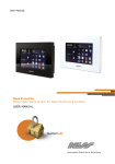
SmartLAN
Installation
Manual
Ethernet interface
The system-on-chip platform used in SmartLAN/G and SmartLAN/SI boards
provides Ness SmartLiving control panels with point-to-point networking capability
and fast connectivity to the internet.
If you wish to take full advantage of all the SmartLAN resources, it will be necessary
to contact your network administrator before configuring the board, as its
operational capabilities depend on the configuration of the network it is working in.
SmartLAN/SI - front view
A
Description of parts
A
RJ45 input for LAN line
B
D
DB9 input for serial line (on
the reverse side)
AUX power supply connector
(only for SmartLiving515)
µSD-card connector
E
RESET button
F
HARD RESET button
C
G
Board power supply LED
H
I
SmartLAN and control panel
connection LED
LAN link LED
L
LAN activity LED
M
100Mbps Mbps conection
speed LED
Transmission/Reception via
BUS RS232 LED
Network conflict LED
N
O
B
C
G
O
M
N
I
P
L
I
SmartLAN/G - front view
A
G
and earth proP Screw location
tection
Q
H
D
µSD-card
(not included)
P
E
F
Q
Ness SmartLAN Manual
1
B
Features
Both boards allow you to configure the control
panel parameters via the LAN using the
Ness SmartLeague programming software.
The SmartLAN/G allows you (the user) to:
Technical
specifications
SmartLAN/SI
SmartLAN/G
Power supply
12 V=
voltage
MAX current
70 mA
90 mA
draw
Operating
-5 / +40 °C
temperature
Dimensions
81 x 54 x 25 mm
MAX capacity of
32 Gb
µSD-card
Security protocol 8 bit encryption
AES-128 bit
PCB code
IN074
IN133
• Send panel-event related e-mails with
attachments
• Interact with the control panel via browser
(Explorer, Firefox, Opera, Safari, etc.) from
any computer with a web-server. After
authentication, the web-server will show:
- zones
- partitions
- timers
- events log
- a virtual keypad (similar to the one actually connected to the control panel).
From the virtual keypad, you (the user) can arm/disarm partitions, bypass/unbypass zones, activate/
deactivate outputs or reset the alarm and tamper memories.
For more details about the use of the web-server, please refer to the User Manual of the control panel
connected to the SmartLAN.
Powering up the SmartLAN board
In order to power up the SmartLAN board you must insert a jumper between pins 1 and 2 of the suitable
connector in the control panel mother board (see SmartLiving Installation Manual).
Configuring the SmartLAN/G board (from PC only)
The SmartLAN/G board can be programmed from any
computer with SmartLeague software.
To install a SmartLAN/G board on a SmartLiving control
panel, work carefully through the following steps.
1. From the User menu on the keypad, go to:
Activations > Internet access
then press
to enable the option.
2. Using the SmartLeague software, access Settings Application Settings.
3. In the Communication type section, select SmartLAN/G.
4. In the IP Address section, type-in the parameters of
the LAN board the SmartLeague application must communicate with:
• IP address
Insert the IP address followed by “:” and the number of
the programming port, when this is not “5004”.
• User Name
• Password
5. Press
.
6. The SmartLeague application will establish a connection to the control panel through the SmartLAN/G
board.
Ness SmartLAN Manual
2
Programming
parameters
SmartLAN/G default
values
IP address
Subnet-mask
User name
Password
Programming port
Web server port
SSL web server port
Gateway
DNS
192.168.1.92
255.255.255.0
admin
pass
5004
80
443
192.168.1.92
192.168.1.92
7. Click SmartLAN settings (on the
left side of the screen).
Press
to view the SmartLAN
parameters and, if necessary, change
the values. Press
to save any new
values.
8. Click the Parameters settings
option. Three sub-options will be
provided (tags at the top of the
screen):
LAN board - this
programming
section will allow you to configure the
LAN board.
• Connection parameters:
•• IP Address
•• Programming port
•• Web server port
•• SSL web server port
•• Subnet mask
•• Gateway
•• DNS
Note
If you change an IP address on this
screen, you must go back to Settings Application settings and type-in the
new IP Address in the respective field.
• Account:
•• User name
•• Password - the
button will allow you to mask/unmask the entered password.
• E-mail parameters:
•• Subject - this field is the e-mail header. Each e-mail, sent via the SmartLAN/G board, will include this header and
a description of the event type. For example, if "SmartLiving 1050 panel Ellis Bell" is typed in the "Subject" field and
a zone alarm occurs, the "Subject" field of the e-mail will show "SmartLiving 1050 panel Ellis Bell [Alarm zone]".
•• Sender - this field is for the e-mail address of the sender.
•• Mail Server - this field is for the SMTP address of the outgoing mail server.
•• Port - this field is for the output port of the mail server (SMTP).
If the STP server requires authentication, enable the Autentication required programming field and enter:
•• User name
•• Password
• DNS dynamic:
If you are dealing with a dynamic DNS with a public IP address, it is useful to have a domain name which will
allow direct connection to the SmartLAN/G in question at all times. The SmartLAN/G supports DynDns.org
services, such as mailhost with dynamic DNS.
Registering with DynDns.org (http://www.dyndns.org) will provide you with a personal third-level Internet name
(for example. myhouse.dyndns.org) and access data (user name, password). The SmartLAN/G will use this data
to link the public IP address with a static Internet name. In this way, access via Internet will be direct as by way
of the distinctive domain you choose.
•• Domain - this is the domain chosen @ DynDns.org (for example. myhouse.dyndns.org).
•• User name - this is the user name chosen during DynDns.org. registration.
•• Password - this is the password chosen during DynDns.org.registration.
•• Update every - this is the interval (in seconds) the SmartLAN/G allows between link updates with the public IP
address.
Ness SmartLAN Manual
3
Contacts - this screen allows you to type in the e-mail
addresses of up to 20 contacts. The e-mail contacts can be
saved on this screen but can also be changed in other parts
of the application (details and instructions to follow).
E-mail parameter configuration - this screen allows
you to configure the parameters relating to outgoing eventassociated e-mails.
Note
E-mails can be associated only with events which are saved
to the events log (“Event ON to log” and/or “Event OFF to
log” options must be enabled).
• Event Type - allows you to select the group of events
you wish to program (Zone alarm, Away/Stay mode,
Terminal tamper, etc.).
The application will show all the events relating to the
selected Type.
The Activations and Retoral screens are the same and allow you to program the notification of the start of an
event (Activation) and its end (Restoral).
• Sel - if this option is enabled (enabled by clicking on the
respective checkbox), it will be possible to program
simultaneously the respective e-mail recipients, message
and attachments (details and instructions to follow).
You can select/deselect ALL events by right-clicking on
the option header (directly on "Sel"), as shown opposite.
• Log - if this option is enabled, a copy of the event record
(as saved to the events log) will be included in the email.
• Recipient - double-click on the box which corresponds to the desired event to access the e-mail contacts
screen and/or change the e-mail addresses of the recipients.
This screen provides 3 buttons:
•• Apply - this option allows you to add/delete recipients
to/from the e-mail contact list associated with the
selected event only.
•• Apply to events in the selected group - this option
allows you to add/delete recipients to/from the e-mail
contact list related to the type of the selected event.
•• Apply to selected control panel events - this option
allows you to add/delete recipients to/from the e-mail
contact list related to the selected control panel events.
The example above shows that when "Apply to events in
the selected group" is enabled, the application will send an
e-mail to Currer Bell in the event of Zone Alarms involving
zones PANEL T01, PANEL T02, PANEL T04, PANEL T05 and
PANEL T06. If, under the same circumstances, "Apply" is
enabled, the application will send an e-mail to Currer Bell
only in the event of Zone Alarms involving zone PANEL T01,
owing to the fact that it is the only one currently active.
Ness SmartLAN Manual
4
• Message - this option will allow you to edit the e-mail
text structure.
Double click on the desired event field to open the
Message window, then type in the respective text (up
to 512 characters will be accepted). Each e-mail text is
capable of containing a direct link to a website or LAN
device (such as an IP camera) with http:// suffix.
The Apply, Apply to events in the selected group
and Apply to selected control panel events buttons
operate in the same way as previously described.
Position the mouse arrow on the Message field, to view the message contents (tooltip function).
• Attach - each event can be associated with an
attachment document/file.
To access Explore, double-click on the field which
corresponds to the selected event.
Note
If you are attaching files to e-mails, be sure that an SDcard is inserted into the appropriate connector on the
SmartLAN/G board (table Description of parts, [P]).
•• The
button will allow you to open a browser of the operative system and select the file you wish to transfer to
the SD-card.
•• The
button will allow you to delete the selected file from the SD-card.
•• The
button will allow you to update the contents of the SD-card.
•• The Apply, Apply to events in the selected group and Apply to selected control panel events buttons
operate in the same way as previously described.
9. Once the programming process is complete, click on the
SmartLAN/G board.
button to send the programming data to the
Note
The programming data will be saved to the SmartLAN/G board and not to the control panel board.
Note
The e-mail service does not guarantee the time within which e-mails and their attached files will be delivered, nor
whether they will be delivered or not.
Customizing the web-server interface logo
SmartLAN / G allows you to customize the logo on the home page of the web-server interface.
1.
2.
3.
4.
Create a directory named “web” inside a SD-card.
Inside the “web” directory save an image file named “logo.jpg”.
Insert the SD-card in the suitable connector (see table Description of parts, [D]).
The logo “logo.jpg” will be loaded until the SD-card is inserted.
Ness SmartLAN Manual
5
Programming the SmartLAN/SI (from PC only)
The SmartLAN/SI board can be programmed solely through the SmartLeague software application.
Following are the steps you must work through when installing the SmartLAN/SI on a SmartLiving control panel.
1. From the SmartLeague software application, select
Settings - Application settings.
2. From SmartLeague Communication type, select
SmartLAN/SI.
3. If you wish to encrypt data:
•• Enable the Encrypt data option on the screen.
•• From the Installer menu, select:
PROGRAMMING Parameters > Data encryption
•• Use the
4. Click-on the
5. Click-on the
button to enable the selected parameter.
button to open a new window.
button to search for the SmartLAN/SI
board in the network. When found, the application will
update the window with the new data.
6. Select Network, to make the SmartLAN/SI configuration compatible with the LAN it is connected to.
7. In the IP Configuration Method section, select
"Static".
8. The main programming section will allow you to
change the:
•• Local IP
•• Port
•• Subnet
•• Gateway
9. In the Operation Mode section, select "Server".
10.If, at any point, you wish to change the password,
access the Option section and, in the Password (TCP
Server) field, click-on Enable then type-in the new password (max 8 alphanumeric characters).
11.Once the configuration is complete, press the
button to send the new configuration to the board,
save it to the database and exit the window.
12.Type-in the new IP Address and Password on the Application settings window.
13.Press the
button to confirm.
Factory default settings
The SmartLAN/G board can be re-inialized by pressing the the “RESET” button (see table Description of parts,
[E]); it is also possible to restore the factory default settings by means of the “HARD RESET” button (see table
Description of parts, [F]).
To delete the current settings, work carefully through the following steps:
1. Press and keep pressing the “HARD RESET” button.
2. The “SYS” LED (see table Description of parts, [H]) blinks for 10 seconds.
3. When the blinking stops, release the button.
Ness SmartLAN Manual
6
Configuring a network
Minimum requirements:
• 1 router/modem connected to the Internet. The router/modem must have
"port forwarding" capability in order to route external connections properly;
• 1 SmartLAN connected to the router/modem.
Additionally, a PC with SmartLeague software (for programming purposes)
connected to a SmartLAN (point-to-point connection using twisted ethernet
cable or connected via router).
A good knowledge of networking and TCP/IP protocol is required during the
SmartLAN board configuration and the Internet connection phases:
Appendix
IP address - The IP address identifies each peripheral distinctly in the network, for example, each computer
connected in an "office" network or directly to the Internet.
The IP address of the SmartLAN board is "static" and therefore cannot be assigned automatically. You can assign
an IP address (192.168.1.92 at default) from the SmartLAN programming window in the SmartLeague software
application. The PC used when first programming the SmartLAN board must have an IP address in the same
address class 192.168.1.xxx (for example 192.168.1.123).
The initial IP address of the SmartLAN board can be changed at a later time, when the network administrator
provides you with one which increases the network capabilities.
Subnet mask - This specifies which address class can communicate with the SmartLAN board.
The mask must be provided by the network administrator. It is set at 255.255.255.0 at default, thus allowing
the SmartLAN board to communicate with all the peripherals with class address 192.168.1.xxx.
TCP/IP port - This identifies a service which a single peripheral in the network can use.
The SmartLAN board uses two TCP/IP Ports:
• The port reserved for web-server access. At default, this parameter is set at 80.
• The programming port (up/downloading). At default, this parameter is set at 5004.
Gateway - This is the gateway that passes traffic from the local net to the Internet. In a minimum
configuration, the gateway coincides with the router.
The IP address of the gateway must be in the same class as the IP address of the local net (for example:
192.168.1.1).
DNS - This is a server which translates Internet names into IP addresses (for example: www.google.com in
209.85.129.99). The IP address of the DNS server depends on the Internet-connection provider (Telecom,
Vodafone, etc.), therefore, must be provided by the network administrator.
SSL - protocol used for HTTPS connections. The security of the connection with the computer is guaranteed by
integrated cryptography. The security of the connection of mobile-phone devices is guaranteed by the SSL
protocol.
A secure HTTPS connection is used via the default SSL port (443) or via the programmed port of the SmartLAN/
G board.
Default SSL port (443): https://192.168.1.92
Customized SSL port (xyz): https://192.168.1.92:xyz
Configuring a router
External access to the SmartLAN board requires knowledge of the public IP address of the router, assigned by the
Internet-connection provider (Telecom, Vodafone, etc.). This address can be either static or dynamic and effects
connections external to the router:
• Dynamic public IP address connections
After a connection, or at set intervals, the provider may assign a modified public IP address to the router. This
operation hinders external access to the router.
In order to solve this problem, many routers have access to services which link dynamic IP addresses with
Internet names (for example: www.dyndns.com). It is necessary to register with a "dynamic DNS host" and
set up the router with the parameters supplied by the service (for example: user, password, domain, etc.). The
router will update the dynamic IP address periodically with the static name chosen during registration (for
example: http://myhouse.dyndns.org). In this way, it will be possible to communicate with the router by
means of the distinct lpublic IP address.
Ness SmartLAN Manual
7
• Static public IP addresses connections
These are connections to a public IP address that is always the same. In this case, it is possible to
communicate with the router directly using the static IP address or by obtaining a domain (for example:
www.myhouse.com) which can be re-addressed to a static IP address assigned by the connection provider.
Once the external connection with the router is established, it is necessary to forward the incoming connections
to the SmartLAN/G board. The previously configured "IP address" and "Port" parameters allow identification of
these connections. The manufacturer strongly recommends that you contact the network administrator during
this programming phase, in order to avoid IP address conflict.
If these services are enabled on the SmartLAN/G board, it will be necessary to open the router screen, reserved
for "port forwarding" (sometimes called "virtual server"), and set up the respective routes:
• Web server port
•• Communication protocol: TCP/IP
•• External port: 8080 (or any other free port provided by the network administrator)
•• Internal port: 80 (or the one selected during the programming phase)
•• IP Address: IP address of the SmartLAN board
• SSL web server port
•• Communication protocol: TCP/IP
•• External port: 443 (or any other free port provided by the network administrator)
•• Internal port: 443 (or the one selected during the programming phase)
•• IP Address: IP address of the SmartLAN board
• Programming port
•• Communication protocol: TCP/IP
•• External port: 5004 (or the one selected during the programming phase)
•• Internal port: 5004 (or the one selected during the programming phase)
•• IP Address: IP address of the SmartLAN board
External access
• To establish external communication with the SmartLAN/G web server via browser (Firefox, Opera, Internet
Explorer, etc.), type-in the configured "public IP address" of the router, followed by the number of the external
forwarding port, as follows:
•• http://www.myhouse.com:8080 (for domains with a Static public IP)
•• http://myhouse.dyndns.org:8080 (if registered at dyndns.org with Dynamic public IP)
• To establish external communication with the SmartLAN/G through the SmartLeague software application,
type-in the configuration parameters (IP address of the router and external forwarding port).
• To establish external communication with the SmartLAN/G through mobile-phone devices via browser, type-in
the configured "public IP address" of the router, followed by the number of the external forwarding SSL port,
as follows:
•• https://www.myhouse.com:443 (for domains with a Static public IP)
•• https://myhouse.dyndns.org:443 (if registered at dyndns.org with Dynamic public IP)
www.nesscorporation.com
SMARTLAN Installation Notes
National Customer Service Centre
Ph: 1300 551 991
[email protected]
All rights reserved. No part of this publication may be reproduced, transmitted or stored in a retrieval system
in any form or by any means, electronic, mechanical, photocopying, recording, or otherwise, without the prior
written permission of Ness.
Ness reserves the right to make changes to features and specifications at any time without prior notification in
the interest of ongoing product development and improvement.
© Ness Corporation Pty Ltd ABN 28 069 984 372
Ness SmartLAN Manual
8