1
Università degli Studi di degli Studi di Padova
FACOLTÀ DI INGEGNERIA
Corso di Laurea in Ingegneria dell’Automazione
Dipartimento di Ingegneria dell’Informazione
Dipartimento di Tecnica e Gestione dei sistemi industriali
Controllo di robot omnidirezionale tramite
Ethercat
Laureando:
Relatore:
Luca Magnabosco
Ch.mo Prof. Ing. Giulio Rosati
Anno Accademico 2012-2013
Controllo di robot omnidirezionale tramite Ethercat
3
Abstract
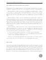
Omnidirectional mobile robots are increasingly popular due to their enhanced mobility. Compared
to the more common car-like robots, they have the superior agile capability to move towards any
position and attaining simultaneously any desired orientation.
The project’s purpose is to control the omnidirectional platform of the Barcelona Mobile Manipulator (BMM) built with the collaboration of the Mechanical Engineering Department of the
UPC. The idea is to control the three motors that move the omnidirectional wheels using EtherCAT
protocol system.
The development of the project requires: a) the study of the communication by EtherCAT
between the PC controller and motors’ drivers that are provided with an EtherCAT module; b)
the development of an EtherCAT master suited to the platform utilization; c) software developing
for both the real-time control by Joystick and the tracking of a planned trajectory.
The software has been developed using Orocos to allow a simple and efficient implementation
of the application, as well as real-time performance, while SOEM library has been used to control
EtherCAT communication.
4
Controllo di robot omnidirezionale tramite Ethercat
Controllo di robot omnidirezionale tramite Ethercat
5
Contents
Abstract
3
Preface
9
1 Introduction
11
2 Background
13
2.1
Omnidirectional Platforms . . . . . . . . . . . . . . . . . . . . . . . . . . . . . . . . . 13
2.2
Omnidirectional wheels . . . . . . . . . . . . . . . . . . . . . . . . . . . . . . . . . . 15
2.3
EtherCAT master . . . . . . . . . . . . . . . . . . . . . . . . . . . . . . . . . . . . . . 16
3 Motivation
19
4 Objectives
21
5 Involved Hardware
23
5.1
Spherical omnidirectional wheels . . . . . . . . . . . . . . . . . . . . . . . . . . . . . 23
5.2
Motors . . . . . . . . . . . . . . . . . . . . . . . . . . . . . . . . . . . . . . . . . . . . 24
5.3
Platform . . . . . . . . . . . . . . . . . . . . . . . . . . . . . . . . . . . . . . . . . . . 25
5.4
Joystick . . . . . . . . . . . . . . . . . . . . . . . . . . . . . . . . . . . . . . . . . . . 26
6 Involved Software
27
6.1
SOEM . . . . . . . . . . . . . . . . . . . . . . . . . . . . . . . . . . . . . . . . . . . . 27
6.2
Orocos . . . . . . . . . . . . . . . . . . . . . . . . . . . . . . . . . . . . . . . . . . . . 36
7 Orocos EtherCAT communication components
45
7.1
Orocos EtherCAT master . . . . . . . . . . . . . . . . . . . . . . . . . . . . . . . . . 45
7.2
Orocos EtherCAT slaves . . . . . . . . . . . . . . . . . . . . . . . . . . . . . . . . . 51
8 Orocos control components
55
6
Controllo di robot omnidirezionale tramite Ethercat
8.1
Joystick component . . . . . . . . . . . . . . . . . . . . . . . . . . . . . . . . . . . . . 56
8.2
Trajectory Generator component . . . . . . . . . . . . . . . . . . . . . . . . . . . . . 57
8.3
Platform component . . . . . . . . . . . . . . . . . . . . . . . . . . . . . . . . . . . . 60
9 Environmental Analysis
73
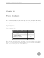
10 Costs Analysis
75
11 Results
77
12 Conclusions
81
13 Future Work
83
A EtherCAT
85
A.1 EtherCAT introduction . . . . . . . . . . . . . . . . . . . . . . . . . . . . . . . . . . 85
A.2 EtherCAT terminology . . . . . . . . . . . . . . . . . . . . . . . . . . . . . . . . . . . 88
A.3 Message syntax . . . . . . . . . . . . . . . . . . . . . . . . . . . . . . . . . . . . . . . 95
A.4 EtherCAT commands . . . . . . . . . . . . . . . . . . . . . . . . . . . . . . . . . . . 98
B User Manual
101
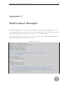
C TaskContext Example
111
Bibliography
115
Controllo di robot omnidirezionale tramite Ethercat
List of acronyms
BMM
Barcelona Mobile Manipulator
DC
Distributed Clock
See Appendix A.3 EtherCAT terminology for further details
DMA
Direct Memory Access
ENI
EtherCAT Network Information
See Appendix A.3 EtherCAT terminology for further details
EPROM
Electrically Erasable Programmable Read-Only Memory
ESC
EtherCAT Slave Controller
See Appendix A.3 EtherCAT terminology for further details
ESI
EtherCAT Slave Information
See Appendix A.3 EtherCAT terminology for further details
ESM
EtherCAT State Machine
See Appendix A.3 EtherCAT terminology for further details
ETG
EtherCAT Technology Group
FMMU
Fieldbus Memory Management Units
See Appendix A.2 EtherCAT terminology for further details
KDL
Kinematics and Dynamics Library
See Section 6.2 Orocos for further details
NIC
Network Interface Controller
OCL
Orocos Component library
See Section 6.2 Orocos for further details
OD
Object Dictionary
See Appendix EtherCAT terminology for further details
OROCOS
Open Robot Control Software
See Section 6.2 Orocos for further details
PDI
Process Data Interface
See Appendix EtherCAT terminology for further details
PDO
Process Data Object
See Appendix A.3 EtherCAT terminology for further details
RTT
Real-Time Toolkit
See Section 6.2 Orocos for further details
7
8
SII
Controllo di robot omnidirezionale tramite Ethercat
Slave Information Interface
See Appendix EtherCAT terminology for further details
SOEM
Simple Open EtherCAT Master
See Section 6.1 SOEM for further details
SDO
Service Data Object
See Appendix A.3 EtherCAT terminology for further details
Controllo di robot omnidirezionale tramite Ethercat
9
Preface
Omnidirectional mobile robots have the ability to move concurrently and independently in rotation
and movement in the plane and this fact is giving them a growing popularity not only in robotic
competition but in the industry too. In the last decades the majority of robotic research has focused
on either mobile platforms or manipulators, but nowadays one of the new challenges is to combine
the two areas into systems which would have both high mobility and the ability to manipulate
objects.
The growing interest is justified not only by the usually growing level of automation in the
industry field but by the service robotic too. Because of the demography of most western countries,
the service robotics will have more and more importance in the next years as the service sector will
suffer an increasing demand while the supply of human operators will be limited. The platform we
are going to present and control in this work consists of a Kuka lightweight Robot mounted on an
omnidirectional base. The target is a mobile manipulator that has a relative small footprint and is
highly maneuverable.
This work wants to obtain the result of a working program that not only communicates by
EtherCAT with the motors, performing the needed configuration, but that should also be able to
allow different control options such as controlling real-time in open loop with a Joystick or tracking
a predefined trajectory. A possible algorithm of obstacle avoiding, performing the above operations,
will be described too.
The EtherCAT choice deals with the different methods that exist to connect I/O devices, in
general, and servodriver, specifically, to a computer to ensure a highly synchronized level of control.
One way would have been to put in the computer a single card for every motor but the EtherCAT
choice was made to avoid problems due to slots requirements in the computer and mainly because
of the high synchronization that this protocol ensures if used with the internal mechanism of DC
clock.
10
Controllo di robot omnidirezionale tramite Ethercat
Controllo di robot omnidirezionale tramite Ethercat
11
Chapter 1
Introduction
The platform that this work aims at controlling, is an omnidirectional non holonomic mobile platform that bases its functional principle on three pairs of omnidirectional wheels developed by
the Mechanical Engineering Department of the UPC. The platform has been dimensioned to be
equipped with a Kuka lightweight robot with the purpose to be totally autonomous, therefore the
space for the Kuka’s controller and for the batteries has been taken into account. The total weight
of the platform without the batteries is about 70 kg. It will be moved by three direct-drive servomotors that are capable of high torques and therefore don’t need reduction. This has been planned
to avoid the play between gears without using highly expensive gearbox.
The communication between the user and the platform will be performed by Wi-Fi while the
on board PC will communicate with the servo drivers and with the Kuka controller using wired
Ethernet connections. For the communication between the PC controller and the servo drivers the
EtherCAT protocol will be used.
This project aims at obtaining a working program that ensures the possibility to control the
platform base at least every millisecond and that should constitute the base for the future development of control algorithms that will control both the base and the Kuka robot together to
interoperate between robots.
The work is structured to guarantee a base software package for motors’ control by EtherCAT
while an upper part of the software will be developed to check the effectiveness of the base software
and the applicability of various controller models.
The software that deals with EtherCAT has been designed having transparency in mind. The
so called EtherCAT master, represented by the program running in the PC that takes care of
the communication, has been developed to be used with different motors or generally different
EtherCAT slaves requiring just a minimal effort to program few lines of code that depends on the
12
Controllo di robot omnidirezionale tramite Ethercat
specific model that is going to be used. This has been done to allow a simple portability of the
code, in case of a motor change, for the next generation platform that will be developed based on
the acquired experience of this one. Moreover such a kind of master could result useful in case
sensors, that are EtherCAT capable, are going to be integrated in the project.
Controllo di robot omnidirezionale tramite Ethercat
13
Chapter 2
Background
2.1
Omnidirectional Platforms
Nowadays the interest of the Industries around mobile robotics is growing mainly because of two
reasons:
• these platforms are particularly useful in service robotics, an application of robotics that is
increasing day by day.
• these platforms could enhance the benefit of automating an industrial process by adding to
a manipulator the possibility of moving it around its work space taking advantage of the
omnidirectionality to maintain the space required for the movement as smaller as possible.
Few companies have recently developed platforms mainly for mobile manipulators. Among them
mainly three options have been examined to verify if one of them could satisfy our needs.
Kuka platform
Kuka sells an omnidirectional platform (fig. 2.1) that can be equipped with various kinds of arm.
It uses four omnidirectional wheels with peripheral rollers. At the moment only the smallest model
[length: 580 mm, width: 380 mm, height: 140 mm] is available and it has a payload of 24 kg and
a maximum speed of 0.8 m/s [22].
CoroBot platform
CoroWare makes available two platform configurations so the user can choose between a 4WD
skid steer base or 2WD differential drive base. As it can be seen (fig. 2.2), they do not use
14
Controllo di robot omnidirezionale tramite Ethercat
(a) Kuka YouBot platform.
(b) Kuka Omnirob platform.
Figure 2.1: Kuka mobile manipulators
omnidirectional wheels, therefore such platforms aren’t omnidirectional. Their characteristics are:
dimensions[length: 304.8 mm, width: 330.2 mm, height: 254 mm], payload of 2.268 kg and a speed
of 0.45 m/s.
(a) 4WD skid steer base.
(b) 2WD differential drive base.
Figure 2.2: CoroBot platforms
15
Controllo di robot omnidirezionale tramite Ethercat
NEOBOTIX platforms
Neobotix offers a range of standard platforms, among them 2 series are interesting for purposes
similar to what we have: 500-line and 700-line. The MPO-500 (fig. 2.3) measures [length:986 x
width:692 x height:409], it has a payload of 50kg/120kg and a maximum speed of 0.8m/s. The
MPO-700 (fig. 2.3) measures [length:711 x width:497 x height:431], it has a payload of 80kg and a
maximum speed of 0.8m/s. The last one uses 4 Steering wheels while the previous one is equipped
with four omnidirectional wheels with peripheral rollers.
(a) MPO-500.
(b) MPO-700.
Figure 2.3: NEOBOTIX platforms
2.2
Omnidirectional wheels
As it has been shown, various omnidirectional platforms that are available on the market use
omnidirectional wheels of various kind with different configurations. But what is an omnidirectional
wheel?
An omnidirectional wheel is a wheel with directional slip, that is a mechanical device to simulate
a link sliding to the ground in a particular direction fixed to the platform or vehicle in question.
The tangential strength between the wheel and the ground is then perpendicular to the direction
of sliding. In the mobile and automated guided vehicles that use this type of wheels there are
basically two constructive solutions (fig. 2.4).
The omnidirectional wheels’ working principle is based upon the fact that rollers can rotate
freely around its axis, so that in every moment the roller touches the ground while rolling freely, to
simulate sliding, in the direction normal to its axis, therefore preventing from slippage in the axial
16
Controllo di robot omnidirezionale tramite Ethercat
(a) Rollers inclinated of 45 respect the wheel axis.
(b) Rollers inclinated of 90 respect the wheel axis.
Figure 2.4: Platforms with peripheral rollers wheels.
direction. Then, controlling the rotation speed of each wheel by its independent motor, the three
platform’s movement degrees of freedom can be controlled.
In this work we are going to control an omnidirectional platform equipped with three omnidirectional wheels whose innovative design has been developed by the UPC Mechanical Engineering
Department. Their design will be explained in section 5.1.
2.3
EtherCAT master
An EtherCAT master is necessary to control the EtherCAT slaves on the network by using the
master-slave principle. It is possible to implement an EtherCAT master to every processing unit
with a standard Ethernet controller. The EtherCAT master is usually implemented on a (industrial)
PC running a real-time operating system to provide real-time guarantees.
EtherCAT masters
There are many EtherCAT master drivers available for different operating systems and hardware
platforms, e.g. Windows, Linux, QNX, PLC’s etc. For Windows the most known one is maybe
TwinCAT by Beckhoff, while for Linux there are lgH EtherCAT Master and Simple Open EtherCAT
Master (SOEM).
TwinCAT
TwinCAT can’t be considered only as an EtherCAT master as it provides a rich environment of
tools that are oriented to turn a PC into a real-time controller as explained in the TwinCAT site.
Controllo di robot omnidirezionale tramite Ethercat
17
The Beckhoff TwinCAT software system turns almost any compatible PC into a real-time
controller with a multi-PLC system, NC axis control, programming environment and operating
station. TwinCAT replaces conventional PLC and NC/CNC controllers as well as operating devices
with:
• open, compatible PC hardware
• embedded IEC 61131-3 software PLC, software NC and software CNC in Windows NT/ 2000/
XP/ Vista, Windows 7, NT/ XP Embedded, CE
• programming and run-time systems optionally together on one PC or separated
• connection to all common fieldbuses
• PC interfaces support
• data communication with user interfaces and other programs by means of open Microsoft
standards (OPC, OCX, DLL, etc.)
It can be considered extremely complete but our choice will be oriented to an open-source
system and drivers so we preferred to evaluate the two other possibilities.
EtherLab
IgH EtherCAT Master is an EtherCAT master library that is written in C by the Ingenieurgemeinschaft IgH. This EtherCAT master library works as a Real Time for the Linux 2.6 kernel and comes
with specific EtherCAT-capable drivers for several common Network Interface Controllers (NIC).
SOEM
Simple Open EtherCAT Master (SOEM) is an EtherCAT master library that is completely written
in C and is targeted for any Linux operating system as a user space application. An important
advantage of this EtherCAT master library is that it doesn’t provide limitations on the applied
design architecture.
Final choice
Finally, for this project, SOEM is preferred over the EtherLab Master because it can be used as
a user space application instead of implementing it as a kernel space application like IgH does,
therefore it is more portable and can be implemented without difficulties in any GNU/Linux with
real-time extensions such as RTAI, Xenomai or RT-Preempt but also in another POSIX compliant
real-time operating system like QNX. This is not easily realizable with IgH because it is completely
implemented in Linux kernel space therefore it contains much kernel specific source code.
18
Controllo di robot omnidirezionale tramite Ethercat
Another important reason that favours our choice of SOEM1 is also that it is portable between
different computers running Linux, without hardware compatibility problems, because all arbitrary
NICs that are able to connect to a RAW socket can be used without any modification. On the
contrary EtherLab always needs a special designed EtherCAT driver for each different Ethernet
controller and therefore limits the compatibility between computer systems with different hardware.
1
The SOEM library will be described in chapter 6.1.
Controllo di robot omnidirezionale tramite Ethercat
19
Chapter 3
Motivation
The present work is focused on the development of a software package that should allow the basic
control of the new mobile omnidirectional platform of the IOC. The work starts with the basic
configuration of the motors and takes care of all the process till the trajectory tracking passing
through the problematic concerning EtherCAT communication with the servo drivers.
This work intends to represent the first step in controlling the omnidirectional base of the
Barcelona Mobile Manipulator, that has been designed to be equipped with the Kuka Lightweight
Robot that the institute already has, in the framework of a greater project, whose target is the
collaboration of more than a mobile manipulator to move objects.
The use of Orocos middleware is intended to allow a simple and efficient implementation of the
application. Moreover it as been useful to ensure real-time performance to the whole code.
The development of a new Orocos EtherCAT master using SOEM has been decided to allow
an easier slave/motor configuration for the next users.
The implementation of a trajectory generator has been decided, even if in the Orocos environment is already present a trajectory generation functionality using KDL, because this last one fits
better to arm-motions and does not present any competitive advantage in trajectory generation for
an omnidirectional platform.[7]
20
Controllo di robot omnidirezionale tramite Ethercat
Controllo di robot omnidirezionale tramite Ethercat
21
Chapter 4
Objectives
The main objective of this work is to make a basic application which controls the mobile omnidirectional platform using as references speeds or torques and that allows real-time performance. To
achieve this objective, this work is divided into three modules:
• EtherCAT communication module
The first problem that has to be solved is the communication between the controller PC and
the servo-motors. As it will be explained these servo-motors have drivers equipped with an
EtherCAT module. Therefore the main objective of this module is to transmit data through
EtherCAT protocol ensuring a high level of synchronization. This objective can be divided
into three parts:
1. Ensuring a fast and easy configuration of the motors with the desired parameters. To
do that SDO EtherCAT messages will be sent.
2. Ensuring a fast communication of both motors’ reference and actual data using EtherCAT PDOs communication.
3. Ensuring a high level of synchronisation of the data toward and backward the motors
using the synchronisation mechanism integrated in EtherCAT and called DC clock.
• Platform’s control module
The second problem that has to be faced is how the motors have to be moved to obtain a
certain movement of the platform. To solve it, the software has to integrate the kinematic
matrices of the platform.
To verify the good accuracy both in positioning and in trajectory tracking that this platform
can achieve using spherical wheels, various controllers, based only in the position read from
the encoders, are going to be implemented. They are intended to be used, in the next future,
integrating the encoders’ information with other position information that will be provided
to achieve a precise odometry of the platform.
• Movement references generation module
22
Controllo di robot omnidirezionale tramite Ethercat
The software also requires the development of a part that could generate the position/speed
reference that the platform has to follow. The program that has to be developed has to exploit
the superior maneuverability of this omnidirectional platform. The trajectory generation has
to be faced in a different way, compared with the habitual car-like platforms, as in our case
a trajectory could be any differentiable function.
The objective is to obtain a real-time trajectory control using a Joystick and the possibility of
obtaining easily a trajectory that passes through path points that the user can define before
the runtime.
23
Controllo di robot omnidirezionale tramite Ethercat
Chapter 5
Involved Hardware
In this part we are going to describe the hardware used to carry out the project.
5.1
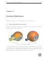
Spherical omnidirectional wheels
The IOC platform is equipped with a new kind of omnidirectional wheel developed by the Mechanical Engineering department of UPC (fig.5.1).
(a) Spherical wheel.
(b) Spherical beparted wheel.
Figure 5.1: Spherical wheels possibilities.
In a wheel of this type there are two components of the rotation angular speed: a component
is in horizontal direction and, along this one, the platform is controlled by the drive motor, the
other component is a free rotation having perpendicular direction to the first. This second rotation
simulates sliding in the horizontal direction, normal to the axis of rotation.
24
Controllo di robot omnidirezionale tramite Ethercat
This new kind of omnidirectional wheel has been preferred mainly because of these two reasons:
• Peripheral rollers wheels, like the ones shown in figure 2.2, present a higher level of uncertainty
in the location of the contact point of each roll with the ground, as it depends on the angle
turned by the wheel. This affects the platform’s odometric accuracy. Spherical wheels don’t
present this problem because each pair touches the ground alternately.
• Constructively, the peripheral rollers wheels are more complex, requiring more elements:
rollers, shafts, bearings, etc.. Besides the rollers bearings have necessarily to be small for
space reasons and this limits the capacity of the wheels. By contrast the spherical wheels are
more simple and have more interior space, allowing to use larger bearings.
5.2
Motors
The motion hardware that the platform is equipped with is represented by:
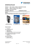
• 3 servopacks Yaskawa model SGDV-2R8AE1A soft version 0021
• 3 option modules SGDV-OCA01A (EtherCAT) with software version 0002
• 3 servomotors Yaskawa model SGMCS-07B3C11 with an absolute encoder UTSBI-B20HB11E
with the resolution of 1048576 pulse/rev and software version 0007
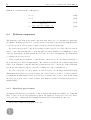
The three servomotors are direct-drive that means they are directly coupled to the load without
a mechanical transmission such as a gear (fig. 5.2). The EtherCAT (CoE) Network Module does not
support EtherCAT Read/Write commands (APRW, FPRW, BRW,LRW), [10] this characteristic
is important to understand further explanations.
Figure 5.2: Motor directly coupled to the wheels pair
Controllo di robot omnidirezionale tramite Ethercat
25
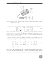
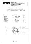
This choice has been done to ensure a high level of odometry1 precision. The three servomotros
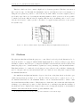
have a rated torque of 7 Nm while the maximum torque is of 21 Nm as it can be seen in figure 5.3.
Using the servopacks it’s possible to control the motors with 3 kinds of reference signal: position,
speed and torque. Moreover, by setting the internal parameter, called operation mode, it’s possible
to switch between the different reference signals, while the motor is running, and to set for every
reference if it is used to define a profile or if it has to be applied as fast as the motor can operate
in a synchro-way.
Figure 5.3: Motor’s characteristics: A)Continuous Duty Zone B)Intermittent Duty Zone
5.3
Platform
The platform, that this work has the purpose to control, has been developed and dimensioned to be
autonomous and to be equipped with the Kuka Lightweight Robot, therefore this prototype has a
medium footprint to have the space to integrate the Kuka controller and the batteries. In the next
future the purpose is to obtain a smaller footprint by a better positioning of the internal hardware.
This platform has to be considered a developing prototype, therefore the possibility of having the
space to integrate and test various hardware has been considered more important compared with
the minimal dimensions.
An omnidirectional platform has three degrees of freedom on the plan, therefore the three generalized independent speeds have to be controlled. These speeds can be coupled one by one to
an omnidirectional wheel so the minimum number of non conventional wheels to achieve omnidirectional maneuverability is three. Employing more than three unconventional wheels has the
advantage of providing more points of contact with the floor, and improving thus the stability of
the platform, but it complicates the design because you need a suspension system or an articulated
chassis to allow that all wheels touch the ground simultaneously.
1
As odometry precision we mean the position precision in function of the wheels’ angle.
26
Controllo di robot omnidirezionale tramite Ethercat
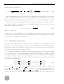
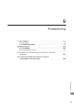
The arrangement of the wheels is another important parameter. In this case, based upon the
previous experience of the mechanical department, [16] it has been decided to place them equally
spaced by angles of 120 degrees.
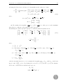
1000
y
3
p2=p3= 333,5
p3
1
vy
780
Gp
x
. O vx
B
p2
2
204
p1= 633,5
200
(a) Platform dimensions X,Y.
(b) Platform model.
Figure 5.4: Actual omnidirectional platform prototype.
Previous considerations have led to the development of this prototype (fig. 5.4).
5.4
Joystick
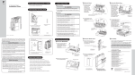
To obtain real-time trajectory control during the runtime, we have decided to use a joystick in order
to have the possibility to control the three generalized speeds, of which the platform is capable, at
the same time.
Figure 5.5: Used joystick: Thrustmaster T-Flight Stick X
To test the platform we have decided to use a normal joystick for PC gaming. The used model
is a Thrustmaster T-Flight Stick X (fig. 5.5).
Controllo di robot omnidirezionale tramite Ethercat
27
Chapter 6
Involved Software
In this part we are going to describe the software that has been used during the project focusing
on the implied characteristics.
6.1
6.1.1
SOEM
What is SOEM?
SOEM is an EtherCAT master library written in C. Its primary target system is GNU/Linux, but
SOEM tries not to impose any design architecture therefore it can be used in generic user mode,
PREEMPT RT or Xenomai. It provides the user application with the means to send and receive
EtherCAT frames.
SOEM is a free software that can redistributed and/or modified under the terms of the GNU
General Public License version 2 as published by the Free Software Foundation.[20]
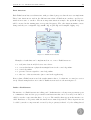
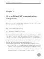
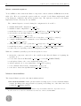
It is up to the user application to provide means for:
• Reading and writing process data to be sent/received by SOEM (fig. 6.1)
• Keeping local IO data synchronised with the global IOmap
• Detecting errors reported by SOEM
• Managing errors reported by SOEM
It is developed by Arthur Ketels and the version 1.2.8 has been recently released1 . To see all
the features SOEM provides, have a look at its site2 . To understand better the used terminology
1
2
On July 2012
http://soem.berlios.de
28
Controllo di robot omnidirezionale tramite Ethercat
as well as the SOEM code, an EtherCAT introduction is provided in the Appendix A.
Figure 6.1: Relatioship between Application and EtherCAT master:
The synchronization of the data-flow between the Process Image and the Application is done, in
our program using Orocos 6.2.
It is important to underline that, to ensure real-time performances using SOEM, it has to be
used with RTNet. To set up it, it can be useful to have a look at the links [15] and [27] that discuss
the subject in the Orocos mailing list.
6.1.2
Main SOEM commands
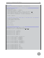
In the developed code some SOEM functions are used. Here they are briefly described.
• ec init(ifname) initialise SOEM, bind socket to ifname.
After the start of the application we need to set up the NIC to be used as EtherCAT Ethernet
interface. In a simple set-up we call ec init(ifname) and if SOEM comes with support for cable
redundancy we call ec init redundant that will open a second port as backup. You can send
NULL as ifname, if you have a dedicated NIC selected in the nicdrv.c. It returns a number
greater than 0 if it succeeds.
• ec config init(usemap) enumerate and initialize all slaves. It requests a BRD (Broadcast
Read) of address 0, all fully functional slaves in the network will respond to this request, and
therefore we will get a working counter(wkc) equal to the number of slaves in the network.
ec config init also sets up the mailboxes for slaves that support it. When ec config init finishes
it will have requested all slaves to state PRE OP. All data read and configured are stored in
a global array ec slave[slave number] that acts as a placeholder for key values.
If the usemap3 option is activated, this function fills the array, if possible, using the correspondent slave’s information stored in ec configlist[], being faster than reading the slave
by EtherCAT through SII. The check is performed comparing the slave’s manufacturer and
3
usemap is a boolean and therefore can be true or false.
Controllo di robot omnidirezionale tramite Ethercat
29
identification number read from EPROM (see appendix A.2 for the EPROM description) to
the same fields saved in the list for every slave in the list.
• ec config map(&IOmap) configure the IOmapping by saving the correct fields of the structure
ec slave.
It will create an IOmap and configure the SyncManager’s (see A.2) and FMMU’s (see A.2)
to link the EtherCAT master and the slaves. The IO mapping is done automatically.
During mapping, SOEM also calculates an expected WKC for the IO mapped together.When
the mapping is done SOEM requests slaves to enter Safe Operational.
• ec config(usemap,&IOmap) is the configuration function that generally the user has to call.
It internally calls ec config init(usemap) and then, if possible, ec config map(&IOmap).
• ec slave[slave number].state = DESIRED STATE changes the field state of the slave number
in the ec slavet structure. The change is imposed after the ec writestate command. If the
slave number is 0 then all the slaves are involved.
• ec writestate(slave number) write slave state, if slave number = 0 then write to all slaves.
The function does not check if the actual state is changed.
• ec readstate reads all slave states in ec slave and return lowest state found.
• ec statecheck(slave number, DESIRED STATE, EC TIMEOUTSTATE) checks if the
slave number has the state DESIRED STATE waiting EC TIMEOUTSTATE. It returns the
requested state, or found state after time-out. This is a blocking function.
• ec configdc() sets DC’s of all slaves to sync with the first, measure propagation delays.
• ec dcsync0 (slave number,active, CycleTime, CycleShift) if active sets DC of slave number to
fire a sync0 event at CycleTime interval with CycelShift offset, both expressed in nanoseconds.
The slave gets triggered at the next whole multiple of the cycle time plus the cycle shift +
100ms and then at every cycle time.
Shift can be used for two purposes:
1. offsetting the trigger moment of slave Y in relation to slave X.
2. offsetting the trigger in multiple cycles. For example if your cycle time is 1ms and the
shift is 1000ms then the first sync pulse is delayed another 1sec. This option can be used
to prevent time-outs of the slaves PDO to sync check too. [21]
• ec send processdata transmits process data (PDO) to slaves.
Uses LRW, or LRD/LWR if LRW is not allowed (blockLRW). Both the input and output
process data are transmitted. The outputs with the actual data, the inputs have a placeholder.
The inputs are gathered with the ec receive processdata function. In contrast to the base
LRW function, this function is non-blocking. If the process data does not fit one datagram,
multiple are used. In order to recombine the slave response, a stack is used. It returns a
number greater than 0 if process data is transmitted
• ec receive processdata receives process data (PDO) from slaves.
Received datagrams are recombined with the process data with help from the stack. If a
30
Controllo di robot omnidirezionale tramite Ethercat
datagram contains input process data it copies it to the processdata structure. timeout is
expressed in microseconds. It returns the workcounter.
• ec SDOread(slave number,index,subindex,CA,psize,p,timeout) It is the functin that execute
the CoE SDO read and it is blocking. It can be used to acces the Dictionary Object in two
ways: Single subindex or Complete Access.
Only a “normal” upload request is issued. If the requested parameter is ≤ 4 bytes then a
“expedited” response is returned, otherwise a “normal” response. If a “normal” response is
larger than the mailbox size then the response is segmented. The function will combine all
segments and copy them to the parameter buffer. It returns the workcounter from last slave
response.
Arguments: slave number= Slave number; index = Index to read; subindex= Subindex to
read, must be 0 or 1 if CA is used; CA = FALSE = single subindex. TRUE = Complete Access,
all subindexes read; psize = Size in bytes of parameter buffer, returns bytes read from SDO;
p = Pointer to parameter buffer; timeout = Timeout in µs, standard is EC TIMEOUTRXM.
• ec SDOwrite(slave number,index,subindex,CA,psize,p,timeout)It is the functin that execute
the CoE SDO write, blocking. It can be used to acces the Dictionary Object in two ways:
Single subindex or Complete Access.
A “normal” download request is issued, unless we have a really small mailbox and small data,
then a expedited transfer is used. If the parameter is larger than the mailbox size, then the
download is segmented. The function will split the parameter data in segments and send
them to the slave one by one.
Arguments: slave number= Slave number; index = Index to read; subindex= Subindex to
read, must be 0 or 1 if CA is used; CA = FALSE = single subindex. TRUE = Complete Access,
all subindexes read; psize = Size in bytes of parameter buffer, it returns bytes read from SDO;
p = Pointer to parameter buffer; timeout = Timeout in µs, standard is ec TIMEOUTRXM.
• ec close() terminate EtherCAT communication and close socket.
6.1.3
Main SOEM variables and structures
Using SOEM in the developed code, the variables that have been mostly used are:
• ec slavecount is a variable that contains the number of the detected slaves.
• ec slave[slave number] is a structure of type ec slavet where there are various fields for the
detected EtherCAT slaves. The slave number=0 is reserved for the Master. The fields
ec slave[i].inputs/outputs contain the pointer for the correspondent PDO data in the IOmap.
There are other important fields such as .name for the slave’s name expressed as a string and
.Obytes/Ibytes, for the size of the inputs and outputs in the IOmap expressed in bytes, while
in .Obits/Ibits the size is expressed in bits. The structure gets filled in by the configuration
Controllo di robot omnidirezionale tramite Ethercat
31
function ec config().
• ec group[group number] is a structure of type ec groupt where there are various fields for
the groups of detected slaves. The structure gets filled in by the configuration function
ec config map group() called by ec config map(). Using it in this way only one group, the
default, group 0 is created and used.
• ec configlist[] is a structure manually filled in the file ec configlist.h. It contains various fields
for every specific slave model. It can be used by the function ec config init(true) to avoid
reading some needed data by accessing a connected slave, that is present in the list, through
SII.
For our slaves, with the current PDO mapping, this line has to be added in the list:
{/*Man=*/0x00000539,/*ID=*/0x02200001,/*Name=*/’’SGDV’’,/*dtype=*/7,
/*Ibits=*/104,/*Obits=*/104,/*SM2a*/0x1100,/*SM2f*/0x00010074,
/*SM3a*/0x1358,/*SM3f*/0x00010030,/*FM0ac*/1,/*FM1ac*/1}
The required data can be retrieved running slaveinfo.c from the SOEM tests or with our
Orocos Master’s correspondent function.
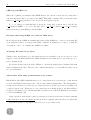
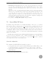
• IOmap[4096] is an array of char that the user has to define when PDO communication is
desired. Its reference is passed to the function ec config map(). The IO mapping is done
automatically, SOEM strives to keep the logical process image as compact as possible. It is
done by trying to fit Bit oriented slaves together in single bytes. Outputs are placed together
at the beginning of the IOmap while inputs follow (fig. 6.2).
Figure 6.2: IOmap memory layout
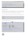
6.1.4
SOEM standard command sequence
To have our program working, SOEM commands have to be done respecting a standard sequence
that takes care of:
32
Controllo di robot omnidirezionale tramite Ethercat
• initializing EtherCAT
• switching devices state (see ESM in the appendix A.2)
• performing PDO mapping (if desired) (see A.3) or modifying other parameters using SDO
(see A.3) commands
• configuring and activating DC clock mechanism (see A.2)
• performing fast data exchange during the process using PDO (see A.3)
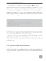
An example of SOEM standard sequence could be:
e c i n i t ( ethNamePointer ) ;
e c c o n f i g i n i t ( usemap ) ;
e c s l a v e [ 0 ] . s t a t e = EC STATE PRE OP ;
ec writestate (0) ;
e c s t a t e c h e c k ( 0 , EC STATE PRE OP , EC TIMEOUTSTATE) ;
// S e t t i n g p a r a m e t e r s and c o n f i g u r i n g PDO mapping u s i n g SDO communication
ec SDOwrite ( . . . ) / ec SDOread ( )
e c c o n f i g m a p (&IOmap) ;
//DC c o n f i g u r a t i o n
i f DC c l o c k i s g o i n g t o be used
ec configdc () ;
e c d c s y n c 0 ( slaveNumber , s t a t e , cycleTime , s h i f t )
e c s l a v e [ 0 ] . s t a t e = EC STATE SAFE OP ;
ec writestate (0) ;
e c s t a t e c h e c k ( 0 , EC STATE SAFE OP , EC TIMEOUTSTATE) ;
e c s l a v e [ 0 ] . s t a t e = EC STATE OPERATIONAL;
ec writestate (0) ;
e c s t a t e c h e c k ( 0 , EC STATE OPERATIONAL, EC TIMEOUTSTATE) ;
// S t a r t i n g PDO data t r a n s f e r
loop { ec sen d p rocessd ata ; e c r e c e i v e p r o c e s s d a t a ; }
// System i s up and s l a v e s a r e r u n n i n g . . .
6.1.5
SOEM and DC clock
As it can be read in the appendix A.2 DC clock is a mechanism used to synchronise the various
devices present in the net. Using SOEM every device can be configured to use DC clock or not. To
use the DC clock mechanism there are mainly two possibilities:
• forcing DC time to sync with that of the master
Controllo di robot omnidirezionale tramite Ethercat
33
• syncing Master’s loop to the DC System Time by reading the ec DCTime variable
The first possibility is presented as the preferred one in EtherCAT documentation but it is very
difficult to find an environment for the master (hardware and OS) that has a good system clock,
therefore the approach that is suggested in SOEM examples is the second one. Indeed only some
embedded systems have a 32KHz clock, some others are not monotonous and since SOEM is OS
and hardware agnostic therefore it opts for the second option. However the first possibility can be
described “easily” in pseudo code. In this case, the cycle, that is cyclically executed to send and
receive PDO data, has to be [21] :
{
send PDO data
r e c e i v e PDO data
new s l a v e r e f e r e n c e time = master time − EtherCAT o f f s e t
FPRW( r e f e r e n c e s l a v e , 0 x910 , new s l a v e r e f e r e n c e time )
execute control operations
w a i t f o r c y c l e end
}
In this example the repeated write operation to register 0x910 of the reference slave will make it
lock to the master time. The EtherCAT offset is the time difference between the master and the
reference slave at start (SOEM starts the reference slave with time=0).
Our final choice has been the second option. It has been implemented taking into account the
SOEM examples and modified to fit with Orocos TimeService.
This part of the code has the objective to obtain a fixed phase relationship between the frames and
the sync0 pulse, remembering that DC mechanism syncs the slaves only amongst each other and
not the master. [21]
6.1.6
Problems faced using SOEM with our slaves
Using SOEM library we faced some problems because, even if it is full of features, it is still being
developed. However all the faced problems have been solved in the last version 1.2.8 that has been
released just few weeks ago, providing not only bug corrections but new functionalities and a useful
tutorial too.
34
Controllo di robot omnidirezionale tramite Ethercat
LRW bug in SOEM 1.2.5
When the beginning experiments with SOEM started, the current version was 1.2.5 that had a
bug involving slaves that do not support the LRW4 EtherCAT command. The problem was in the
function ec config init() and had been solved in the subsequent versions.
To go on, using 1.2.5 with this kind of slaves the “temporary” solution was to add the line
“ec group[0].blockLRW = 1;” before the first call to ec send processdata/ec receive processdata
functions in the program linking towards SOEM.
DC issue when using SOEM 1.2.5 with not LRW slaves
From a thread in the SOEM user mailing list resulted that SOEM 1.2.5 could not work using DC
clock with slaves that do not support the LRW command. Fortunately we could go on with the
development of the code obtaining the SOEM 1.2.6 alpha.
Activating DC mode in our slaves
Usually a slave should just lock to the signal whenever it is available, but, in our case it does not
happen because the EtherCAT module SGDV-OCA01A decides what mode to use in the pre-op to
safe-op transition.[21]
It reads the sync0 registers from the PDI side to check if the master has programmed DC with
sync0 command in the slave. Therefore the command sync0 has to be sent while the slaves are in
pre-operational state.
Alarm AA12 when using synchronisation error counter
EtherCAT module SGDV-OCA01A has a sort of counter [that can be deactivated] to verify if it has
received valid PDO in last sync0 cycles. The module manual explains that: “The Internal Error
Counter is incremented by 3 if the process output data is not updated (a no Receive (SM2) event
occurs) at Sync0 event. When the process output data is normally updated, the Internal Error
Counter is decremented by 1. The Internal Error Counter is reset when the ESM state is transited
to OP from SAFEOP.” [10]
Using our slaves, without this counter, avoids any problem but, if the slave is started with this
counter switched on, the error AA12 appears from the beginning, when the slaves are still in the
4
Logical Memory Write: see Appendix A.3 EtherCAT terminology for further details
Controllo di robot omnidirezionale tramite Ethercat
35
configuration phase.
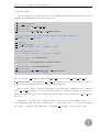
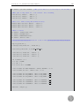
The problem has been analysed writing to the SOEM mailing list [21] and finally was solved
changing the SOEM standard sequence in this way:
e c i n i t ( ethNamePointer ) ;
e c c o n f i g i n i t ( true ) ;
e c s l a v e [ 0 ] . s t a t e = EC STATE PRE OP ;
ec writestate (0) ;
e c s t a t e c h e c k ( 0 , EC STATE PRE OP , EC TIMEOUTSTATE) ;
// S e t t i n g p a r a m e t e r s and c o n f i g u r e PDO mapping u s i n g SDO communication
ec SDOwrite ( . . . ) / ec SDOread ( )
ec configdc () ;
e c c o n f i g m a p (&IOmap) ;
e c d c s y n c 0 ( slaveNumber , s t a t e , cycleTime , s h i f t )
// S t a r t i n g PDO data t r a n s f e r
loop { ec sen d p rocessd ata ; e c r e c e i v e p r o c e s s d a t a ; }
e c s l a v e [ 0 ] . s t a t e = EC STATE SAFE OP ;
ec writestate (0) ;
e c s t a t e c h e c k ( 0 , EC STATE SAFE OP , EC TIMEOUTSTATE) ;
e c s l a v e [ 0 ] . s t a t e = EC STATE OPERATIONAL;
ec writestate (0) ;
e c s t a t e c h e c k ( 0 , EC STATE OPERATIONAL, EC TIMEOUTSTATE) ;
// System i s up and s l a v e s a r e r u n n i n g . . .
Moreover the line ec FPWRw(configadr, ECT REG ALCTL, htoes(EC STATE SAFE OP) ,
EC TIMEOUTRET); of the function ec config map() in the file ethercatconfig.c has to be removed
to prevent the automatic switch of the state to Safe Operational.
The error was caused because the first sync0 event takes place 100ms after the command
while ec config map() function can take more time, therefore could happen that there were various
milliseconds with the sync0 event cycling but with the master still executing the ec config map()
function.
Anyway the code written and explained in these paper uses the usual SOEM sequence to be
more reutilizable with other slaves. Using this code our hardware can be controlled deactivating
the counter or setting the CycleShift in the command ec dcsync0() to an appropriate value.
36
Controllo di robot omnidirezionale tramite Ethercat
6.2
6.2.1
Orocos
Introduction
Orocos is a project that aims at a general-purpose, open source, modular framework for robot
and machine control. Today, The SourceWorks5 is the main contributor to the Orocos toolchain’s
real-time infrastructure, while many other organizations build on top of that. The Orocos RealTime Toolkit is not an application in itself. It provides the infrastructure and the functionalities
to build robotic applications in C++. One of its advantages is the Real-Time Toolkit (RTT) that
allows real-time guarantees. This library has been developed to run on top of a (real-time) Linux
operating system.
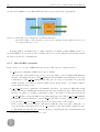
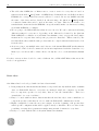
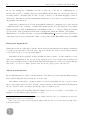
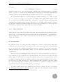
The Orocos project supports three C++ libraries: the Real-Time Toolkit (RTT), the Kinematics
and Dynamics Library (KDL), the Bayesian Filtering Library (fig. 6.3).
(a) Orocos Libraries.
(b) Orocos Real-Time Toolkit.
Figure 6.3: Orocos Libraries and General idea
While RTT has an important role in this project, the other 2 libraries are not used. Orocos
provides another library too, the Orocos Component library (OCL) that is partially used, mainly
for the Reporter Component. The RTT provides, among other things:
• Lock free, thread-safe, inter-thread function calls.
• Communication between hard Real-Time and non Real-Time threads.
• Synchronous and asynchronous communication between threads.
5
http://www.thesourceworks.com
37
Controllo di robot omnidirezionale tramite Ethercat
• Application and platform independent implementation.
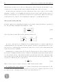
6.2.2
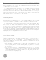
The TaskContext object
An Orocos application built with the RTT is based on TaskContexts. A TaskContext is an active
object which offers thread safe and efficient ports for (lock-free) data exchange. Furthermore a
TaskContext can react to events, process commands, or execute Finite State Machines in hard
real-time. It can be configured on-line through its interface (set/get values) and through XML
files.
In a TaskContext data flow through ports and are manipulated by algorithms in the component.
It can be seen as a software component with an own frequency and priority, but it depends on
the used operating system if these periods and priorities are executed correctly. Every user can
implement its own TaskContext object that is similar to a normal C++ class (For an example of
a TaskContext have a look at the Appendix C).
(a) TaskContext with its activity.
(b) TaskContext structure.
Figure 6.4: TaskContext representation
The “motor” of a TaskContext consists in its Activity that is the thread that executes the
operations required by the updateHook function. TaskContext’s Activity can be periodic or no
periodic, can have a priority and can be a slave Activity that means it can be executed from the
master Activity.6
TaskContext object can communicate with other tasks mainly in 2 ways:
• by Ports that are real-time and thread-safe “variables”
• using its interface with its Attributes, Properties and Operations (see section 6.2.2)
The important difference between these two ways is that, while a component can communicate
6
We are going to use this kind of activity in our code that can be consulted as a self- explaining example.
38
Controllo di robot omnidirezionale tramite Ethercat
with another by ports simply after that ports have been connected, to use another component’s
interface, the two components have to be set as peers.
This is just a simplified description of a TaskContext compared with the Orocos Documentation.
To have a complete information about TaskContext potentialities have a look at “The Orocos
Component Builder’s Manual” [28].
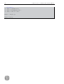
To obtain the basic files that have to be modified to personalize your component, the command
is:
$ o r o c r e a t e −pkg myTasK
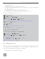
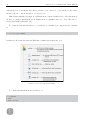
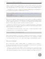
It makes a folder with the name myTask that contains various files (fig. 6.5).
myTask
An Orocos controller package.
This directory can be created with the command:
orocreate-pkg myTask
Uses the USEOrocos-RTT.cmake
macros
CMakeLists.txt
manifest.xml
Describes Cross-packages
dependencies in XML
start_myTask.ops
Start-up script
myTask.hpp
One hpp file for each component
myTask.cpp
One cpp file for each component
property.cpf
Component property file.
These are optionally loaded for each
component and contain application
specific values for each property
Figure 6.5: Orocos Component Package
To compile and install them the user has to do:
$ cd myTask
$ make
$ make i n s t a l l
Controllo di robot omnidirezionale tramite Ethercat
39
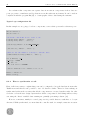
Basic functions
Each TaskContext has several functions, with pre-defined purposes, that the user can implement.
These basic functions are used in the different states that a TaskContext can have, and let it to
switch from a state to another. The most important function is maybe the updateHook() that
will be executed in the running state at a specified frequency. The other functions initiate a state
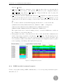
change and they are configureHook(), startHook(), stopHook() and cleanupHook()(fig. 6.6).
Figure 6.6: TaskContext’s states
Examples of tasks that can be implemented in one or more TaskContext are:
• to read/write data from I/O devices via a driver.
• to convert this data in a physical meaningful form for the control algorithm.
• to control algorithm.
• to generate reference signal for control algorithm.
• to take care of the user interface (user controls the application).
If more than a TaskContext is used the synchronization has to be taken into account (see section
6.2.4). Visual examples where more then a TaskContext is used are shown in figure 6.7.
Inside a TaskContext
The interface of a TaskContext is its “calling card”. In this interface a Component presents its ports
to communicate data and few proper variables and functions that can be seen and/or modified or
called by another component that has to be a peer. The variables that appear in the interface are
called Attributes or Properties while the functions are named Operations. These Operations can
be called by another component and executed by the proprietary’s thread or by the calling thread.
40
Controllo di robot omnidirezionale tramite Ethercat
(a) TaskContexts’ configurations and connections.
(b) Example using various TaskContexts.
Figure 6.7: TaskContexts’ connections and organization
The possibility of seeing each other interface depends from the peer relationship between components.
Attributes and Properties
A TaskContext may have any number of attributes or properties, of any type. They can be used
by programs in the TaskContext to get (and set) configuration data. The task allows to store any
C++ value type and also knows how to handle Property objects. Attributes are plain variables,
that can be changed during the run-time, while properties, that is advised to keep constant7 during
the run-time, can be written to and updated from an XML file.[28] These last ones are intended to
be used mainly for configuration purposes because their changes are real-time but not thread-safe.
Services
Various functions can be implemented in services and then added to a TaskContext. Basically
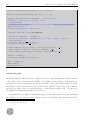
Services are components without the execution engine or, in other words: service=component“thread”-“hooks” so they can be considered “light components”.
6.2.3
TaskContext deployment
When the desired task, for example, myTask has been compiled and installed the user can start to
use it interacting with the Deployer component. This application consists of the DeploymentComponent which is responsible for creating applications out of component libraries and the TaskBrowser
7
They can be changed during the run-time but it is not recommended.
Controllo di robot omnidirezionale tramite Ethercat
41
which is a powerful console tool which helps you to explore, execute and debug components in
running programs [28]. The TaskBrowser is itself a component, developed for user interaction with
other components and it can be connected only to one component at a time showing its interface.
Generally a user can deploy [=launch the programmed TaskContexts] directly using the Deployer. In this case the standard command sequence would be:
$ d e p l o y e r −g n u l i n u x // Writing i n t h e c o n s o l e you s w i t c h t o D e p l o y e r a p p l i c a t i o n
import ( ‘ ‘ myTask ’ ’ )
loadComponent ( ‘ ‘ DesiredName ’ ’ , ‘ ‘ myTask ’ ’ )
However in case of using more than a Component, or in case you desire to set easily some parameters
each time, you would be interested in doing that in an “automated” way without writing each time
the same commands in the Deployer. To do that there are two different solutions that have a little
difference in syntax. They are dynamic deployment and static deployment.
In the static deployment components are fixed at compilation time using the oromain syntax
that lets you write a C++ program obtaining its executable file, that automatically loads the
Deployer and all the desired TaskContexts.
In the dynamic deployment the user has to edit a text file, for example “myConfiguration” that
can have the extension .ops or .xml and use the command:
$ d e p l o y e r −g n u l i n u x −s m y C o n f i g u r a t i o n . ops
There is an important difference between using a configuration file with the extension .ops and with
the extension .xml. It is the different syntax that the user has to respect. In this project mainly
.ops configuration files are used so we are going to make examples only with this kind of syntax.
The reporter component
Before seeing the first “complete” minimal example of a configuration.ops it is compulsory to
introduce another important component of Orocos, the OCL::ReportingComponent for monitoring
and capturing data exchanged between Orocos components.
Each Orocos component can have a number of data ports. The user can configure the reporting
components so that one or more ports, of one or more peer components, are captured. The reporting
components can work sample rate based or event based. A number of file format can be selected.
42
Controllo di robot omnidirezionale tramite Ethercat
In conclusion this component can capture data from various components, if these data are
ports, properties or attributes and log them in a text file with various formats. It can be used in
conjunction with the program Kst [19] to obtain graphs of these data during the run-time.
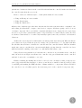
Typical .ops configuration file
In this example we are going to load two components, connect their ports and set them as peers.
import ( ” master ” ) ;
import ( ” s l a v e ” ) ;
// Load t h e components we a r e g o i n g t o u s e
loadComponent ( ” Master ” , ” master ” ) ;
loadComponent ( ” S l a v e ” , ” s l a v e ” ) ;
s e t A c t i v i t y ( ” Master ” , 0 , 1 0 ,ORO SCHED RT) ;
c o n n e c t P e e r s ( ” Master ” , ” S l a v e ” ) ;
// Here we u s e t h e master ’ s a c t i v i t y t o run t h e s l a v e
s e t M a s t e r S l a v e A c t i v i t y ( ” Master ” , ” S l a v e ” ) ;
var ConnPolicy c p 1
c p 1 . type = DATA
cp 1 . s i z e = 1
c p 1 . l o c k p o l i c y = LOCKED
c o n n e c t ( ” P l a t f o r m . p o r t ” , ” Master . p o r t ” , c p 1 )
Master . c o n f i g u r e ( ) ;
Master . s t a r t ( ) ;
6.2.4
How to synchronize a task
First of all it’s necessary to explain that ports can be configured to keep the last data from another
TaskContext and that it’s also possible to save old data in a buffer. Therefore data-exchange is
synchronized without the necessity that all the components are executed synchronously. In other
words Orocos lets the user design a system where all the components do their things whenever they
can, using the “latest” available data ensuring an optimally performing solution. [29]
However, sometimes, mainly for control purposes it’s possible that two tasks have to be synchronized. With synchronized, we mean that the controller task, for example, starts its execution
Controllo di robot omnidirezionale tramite Ethercat
43
just when it obtains new data from the controlled task and that the controlled task reads data from
the controller just when they are ready.
In Orocos there are different ways to obtain synchronization between tasks:
• Using an Eventport between tasks
• Using SlaveActivity
• Using the TimeService
All these three different approaches have their merits but if the system is rather “centralized” the
whole thing (read hardware, compute control action, output to hardware again) could be done in
one single component. Moreover if all the computational functions are designed in a decoupled way,
it won’t be a problem to put them in separate components later on, when really necessary. In other
words these solutions have to be taken only if strictly required, since they can lead to an undesired
behaviour.
An EventPort is an InputPort which wakes our task up when data arrives.[28] When the Eventport solution is adopted with an aperiodic activity, the priorities have to be set right such that
the scheduler knows it has to schedule the controller after the controlled thread. This is somewhat
fragile since any process/thread in our system with higher priority than the controller, but lower
than the hardware, running on the same core, will disturb this balance. [29]
Using SlaveActivity guarantees at least that the controller is as performant as the controlled
task, but indeed it is fragile as well since the controller only gets as much time as the controlled
task and doesn’t scale over multiple cores. [29]
Finally consulting the mailing list we have been lead to the conclusion of using eventports fore
some components and SlaveActivity for others, even if the more suitable solution would probably
be an RTT patch making the EDF scheduler of Linux available to components. This would allow
the controller to set a deadline equal to the next start period of the controlled component. [29]
44
Controllo di robot omnidirezionale tramite Ethercat
Controllo di robot omnidirezionale tramite Ethercat
45
Chapter 7
Orocos EtherCAT communication
components
In this part we are going to explain the software implementation of the Orocos components that
provide the communication through EtherCAT.
7.1
Orocos EtherCAT master
7.1.1
Developing a SOEM/Orocos master
As described, SOEM has a simple portability and doesn’t provide any limitation on the applied
design but it requires a program that manages the calls to the functions that it gives in the correct
order, taking care of the data coherence when using high frequency PDO data transmission. To
obtain this objective, the Orocos community has already written an Orocos component that, linking
towards SOEM, takes care of the EtherCAT communication managing inputs and outputs data that
are regularly presented to the ports of this component. It is a really well done transparent master
that uses a unique TaskContext for the master and automatically extends its functionalities to
manage the connected EtherCAT slaves using plugins and RTT::services.
Anyway it presents some implementative characteristics that limit its usefulness in our project:
• Orocos doesn’t provide, yet, the possibility of using the marshalling plugin so that it can
marshal the properties of another service and as in this architecture (SOEM/Orocos Master)
every slave is a service, it would be impossible to use this powerful middleware to load
automatically properties from an xml for every slave in the Network. To obtain that, the
marshalling plugin has to be extended but it is a work outside our target.
46
Controllo di robot omnidirezionale tramite Ethercat
• The table that SOEM/Orocos Master uses to create a service for every slave is based on
names from the field ec slave[i].name of SOEM library. If this field is not well filled, in slave’s
EPROM, the correspondent driver service will not be created. In our case SOEM can’t find
the name of the driver and as described in ethercatconfig.c the function ec siifind() makes
a constructed name that can’t be used as the name of a class. Therefore the absence of a
standard name, memorized in the EPROM correspondent field, makes our drivers not working
at all with SOEM/Orocos Master.
• We are going to use EtherCAT slaves that are servo-motors. We can be interested in having
different settings for every motor, depending on the different load caused by the platform.
With SOEM/Orocos Master we would miss a mechanism to have very specific driver implementations for a specific slave and specific properties for that slave. This is caused by the
fact that all the slaves with the same product name are coupled with an identical service load
from the table.
• As we are going to use multiple axis control, the use of the internal EtherCAT synchronization
mechanism of DC clock is recommended and it isn’t implemented with the actual Orocos/Master yet, even if it would be a little effort to modify the code to work with this mechanism
too.
For these reasons we have decided to write a different Orocos EtherCAT Master that meets the
needs of our application.
Basic ideas
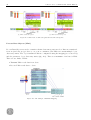
Our Master has been developed with four basic ideas in mind:
1. Being transparent, that means that the Master component deals only with the task to transmit
data over EtherCAT. Data for every slave are managed, inside the computer, by another
Orocos component, specific for every slave, that we can call “virtual slave”. There is a
“virtual slave” for every “real slave”.
2. Easy to be used with new slaves, that means that the user has only to write a small Orocos
component specific for his slave in order to make the EtherCAT communication works.
3. Highly configurable because the user can configure, from the beginning, each specific slave
with a specific configuration that will be applied exactly to this slave. Moreover there is the
possibility of setting slave’s parameters simply using an xml document for every slave.
4. Ready to be used with the DC clock synchronization mechanism.
Controllo di robot omnidirezionale tramite Ethercat
47
About the implementation
As detailed, our EtherCAT Master has been developed using the Orocos middleware to ensure realtime performances and to provide an easy data-flow managing, while the EtherCAT communication
has been handled using the SOEM library.
An Orocos TaskContext for every slave
As explained, we have decided to have a “virtual slave” for every slave that is connected through
EtherCAT. We can imagine that for each “real slave” there is a sort of “virtual slave” that takes
care of the slave’s data that are sent through EtherCAT and that are saved in the Master IOmap
(see section 6.1.3).
In our case, this “virtual slave” is simply an Orocos TaskContext with specific code that depends
from the slave hardware and from its desired use. This principle can be considered a nonsense
because the “virtual slave” can’t communicate directly with its real pair without passing through
the Master1 but this solution has been chosen to allow Master transparency and to have the
possibility of loading properties using the Orocos Marshalling service. Moreover the possibility of
using slave activities (see section 6.2.4) fits perfectly this case.
The feature of loading properties using the Orocos Marshalling service has been considered
really useful in order to give the user a simple way to change all the slave’s parameters editing
simply an xml with the data that he reads in the slave’s manual.
Virtual slave matching
With the previous idea in mind the problem was how to perform the matching between the “virtual
slave” and the “real slave”. There are various possible solutions.
The existent SOEM/Orocos EtherCAT Master uses a table and automatically matches the
slaves with their correspondent service basing its choice upon the slave product name. This is
an automated solution that results really simple for the user that has to do nothing. Anyway it
represents a small lack of configurability because the user can’t control two slaves that have the
same product name in a different way2 . For this reason it has been decided to let the user set this
matching manually in order to allow a higher configurability at the cost of a lower automation.
1
2
An update of the “virtual slave’s” variables affects the “real slave” only after the Master update.
For example if the user desires to control a motor by torque and another motor by speed and these two motors
have the same product name it would be a problem. The problem is caused because first of all they need a different
PDO mapping and probably the torque and speed variables haven’t the same dimensions and/or require different
calculations and these needs can be satisfied only by two different “virtual slaves”.
48
Controllo di robot omnidirezionale tramite Ethercat
With our Master the user that knows the slaves’ position along EtherCAT3 and that has created
an Orocos component for his slave has to set every “virtual slave” as a peer of the Master in the
correct order. It’s this order that affects the “real-virtual” slave matching. In this way the first
“real slave” will be matched with the first Master’s peer and so on.
Master-Slave data exchange
Next problem we had to face was how to exchange data between the Master component and the
“virtual slaves” components. Usually components data exchange in Orocos is performed by ports
in order to be thread-safe, however using SlaveActivity we use an unique thread for the Master and
the “virtual slaves”. For this reason any data exchange between them is automatically thread-safe.
Taking into account the above considerations we have two possibilities to exchange data:
• we can use ports
• we can copy the data in the correct address in the Master IOmap directly from the “virtual
slave”
Both solutions present advantages and disadvantages.
Using Ports
In the first implementation the use of ports will ensure data to be thread-safe even when not
using SalveActivity but presents the problem that the Master, at the beginning, doesn’t know
how many slaves will be connected and above all doesn’t know which data they are going to
send4 . This information is known only after the PDO mapping and after that the command
ec config(usemap,&IOmap) has been executed by the Master.
It is important to underline that as the Master doesn’t know how many slaves will be connected,
it doesn’t know how many ports it has to create. But in Orocos you have to declare the ports you
are going to use in the Component when writing the code. To solve the problems we have declared
the ports as “RT T :: OutputP ort < P DOstream > ∗output; RT T :: InputP ort < P DOstream >
∗input;” where output and input are vectors of ports and PDOstream is a vector of unsigned char.
This data type has been added to Orocos using the functions serialize() and PDOstreamTypeInfo()5 .
Using these vectors the problems of port number and port dimension have been solved.
These vectors are sized after the command ec config(usemap,&IOmap) when the variables
ec slavecount and ec slave[i].Ibytes/Obytes are updated. These ports are automatically created
3
The user can check the slaves position setting the option Master.onlySlaveInfo to true in the .ops. (see the .ops
example in section 7.2)
4
This depends from the PDO mapping.
5
To understand in which way this kind has been added to Orocos, have a look at the file PDOstream.h inside the
folder soem master.
Controllo di robot omnidirezionale tramite Ethercat
49
and connected.
Copying data directly
The implementation of the second solution, where data are directly copied in the correct address,
is more simple. Besides it avoids waste of time that ports cause, but it can represent a problem
when the user who doesn’t use DC clock uses “virtual slaves” with a proper activity. Indeed this
implementation has to be used in conjunction with SlaveActivities to ensure that the data copying
is thread-safe.
With this solution, the Master simply passes the “virtual slave” the information it needs. This
information contains the directions of the slave’s data6 and their size. This information is passed
after that the command ec config(usemap,&IOmap) has been executed by the Master.
Both solutions ensure that every “virtual slave” manages input and output data from the real
slave, establishing an univocal relationship and both of them have been implemented.
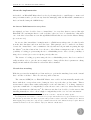
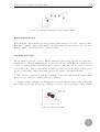
A scheme that can be useful to understand our application can be seen in figure 7.1.
Figure 7.1: Application Scheme
6
These data are contained in the IOmap and have two different fields: one for the data to read from EtherCAT
and the other one for the data to send.
50
Controllo di robot omnidirezionale tramite Ethercat
Master command sequences
To use SOEM, we have written the Master component so that it calls the SOEM functions in the
right order. Here we present the sequences that are executed by the Master implemented with
ports during its configurehook() and its updatehook(). The sequences executed by the Master
implemented in the other way are very similar.
The command sequence executed during the configuration hook would be:
1. initialize EtherCAT configuration: ec init()
2. initialize default configuration: ec config init()
3. switch slaves’ state to pre-operational: ec slave[0].state = EC STATE PRE OP
4. check if there are the same number of real and “virtual slaves”:
if (sched list.size() != ec slavecount)
5. call sequentially the configuration hook of every slave: sched list[i]->configure()
6. configure SOEM IOmap to contain the correct PDO data of all slaves:
ec config map(&m IOmap);
7. switch slaves’ state to safe-operational: ec slave[0].state = EC STATE SAFE OP
8. switch slaves’ state to operational: ec slave[0].state = EC STATE OPERATIONAL
9. resize each port depending on the PDO mapping performed for every slave.
While the commands cyclically repeated in the update hook are:
1. inform the component connected to the eventPort sync that the Master is beginning the
updatehook 7 .
2. receive slave data from EtherCAT ec receive processdata(EC TIMEOUTRET)
3. send updated data to the correct virtual slave using ports
4. call the updatehook of every virtual slave sched list[i]->update()
5. read command data from the “virtual slaves” using ports
6. send data to slaves through EtherCAT ec send processdata()
Master’s functionalities
The designed Master provides other functionalities such as:
• DC clock mechanism: if this option is activated, setting a period of 0 seconds in the Master
activity, the Master auto-triggers itself every sync0 period taking care of the drift of its clock,
reading the ec DCtime variable8 .
7
8
This port would be used to synchronise the Master Component with the Platform component in our case.
See the section 6.1.5 to have more information about the use of DC clock with SOEM.
Controllo di robot omnidirezionale tramite Ethercat
51
• information of every slave printed in a text file. The basic information about the slave
as producer ID, product ID, name and position along EtherCAT, but also a more complete
information, such as the PDO mapping and the complete Object dictionary, could be printed
in the file.
This function could be especially useful when the Master is used for the first time with new
slaves in order to check if the slave’s position is the position that the user supposed. It is
of great importance since the position of the real slave should be the same as the order of
setting “virtual slaves” as Master’s peers. When this function is activated the master only
reads the information from the slave and doesn’t perform the configuration. It simply reads
the actual slaves’ configuration and stops its execution.
• the possibility of sending SDO requests during the run-time.
7.2
Orocos EtherCAT slaves
As explained, the user that wants to use our Master has simply to write a piece of code that is
slave dependent. This code, that is specific for the used slave, has to be written in the form of an
Orocos component and has to inherit from soem slave and not from RTT::TaskContext in order to
have some functionalities already implemented. Each slave component can be loaded and become
a “virtual slave”. Each one of these components can differ from the others because it is written to
be used with a different “real slave”9 or because it uses a different PDO mapping and consequently
different control variables.
Generally a slave can directly execute calculations with the data that it receives from the Master.
In our case we use the “virtual slaves” only to configure the hardware and to order the received
variables in a way that fits better our deeds. Moreover component SGDV slave can be considered
as an example where the DC clock mechanism is used.
About the configuration
The configuration in an EtherCAT slave has mainly two purposes:
1. choosing which data would be updated, usually with high frequency (PDO). This procedure
is called PDO mapping (see appendix A.3) and it is done with a sequence of SDO calls.
2. setting parameters such as maximum speed, ecc... Each parameter’s value is sent to the slave
using an SDO call.
9
A slave that has a different hardware and different functionalities.
52
Controllo di robot omnidirezionale tramite Ethercat
In our case, during the configuration we have to take care of the Orocos communication too,
therefore the ports10 , to exchange data between the Master and the slave, are created and connected.
It is important to underline that we have decided to hard code the PDO mapping because it
changes the data that are updated using PDO. In this way we prevent severe problems caused by
any unwanted modification.
Other slave’s parameters are read from an xml file during the configuration procedure and automatically sent to the “real slave” by SDO calls. In this way the user can change in a very simple
manner parameters such as maximum speed, maximum torque, ecc... only by reading the information about the desired parameters in the slave’s manual and editing the xml file consequently.
This file has for every slave the name configuringXMLSlaveName position?.xml where SlaveName
is the name of the deployed virtual slave, while ? is its position in the EtherCAT bus used by SOEM.
During the updatehook
During the update hook the slave reads the data from its real pair and then performs the calculation
or sends/receives the data to/from another component. At the end of the loop new data are written
to its ports11 ready to be read from the Master.
Generally it is in the updatehook that calculations, that we want to execute with the received
data, can be implemented. In our case in the updatehook we don’t execute any calculation but
there is a part that is executed only the first times and that takes care of the correct steps that the
slave has to do before becoming operative and, in our case, gives power to the motors.
About synchronisation
In our implementation to achieve synchronisation, every slave is executed with the Master thread.
It is obtained using the SlaveActivity (see section 6.2.4).
Since Master’s and slaves’ operations will be executed sequentially, the use of ports between
these components could be avoided. Because of these reasons, we have implemented the Master in
the two described ways: one with ports and the other one without ports.
If you are interested in having different runtime periods for every slave, or in scaling over
multiple cores the Master with ports has to be used.
10
These ports are used only by the first implemented Master while the other one communicates the slaves the
addresses where they have to read and write.
11
These ports are used only by the first implemented Master while the other one copies the data in the right address
in the Master IOmap.
Controllo di robot omnidirezionale tramite Ethercat
53
Master Deployment
We are going to show an example of Master deployment in order to explain how the user has to use
the .ops file to let the Master match the “real slaves” with the “virtual slaves” in the correct way.
Moreover in this example it is explained how to set the Master to use DC clock or the free
running mode. In the lower part of the example Master properties are set. They can be used to
print slaves’ information or to change the used NIC port.
EtherCAT Master configuration.ops
import ( ” u s e r v i r t u a l s l a v e 1 ” ) ;
import ( ” u s e r v i r t u a l s l a v e 2 ” ) ;
import ( ” soem master ” ) ;
// Where u s e r v i r t u a l s l a v e 1 an u s e r v i r t u a l s l a v e 2 a r e Orocos components
// t h a t t h e u s e r has w r i t t e n i n h e r i t i n g from s o e m s l a v e .
// Load t h e components we a r e g o i n g t o u s e
loadComponent ( ” Master ” , ” soem master : : SoemMasterComponent” ) ;
loadComponent ( ” S l a v e 1 ” , ” u s e r v i r t u a l s l a v e 1 ” ) ;
loadComponent ( ” S l a v e 2 ” , ” u s e r v i r t u a l s l a v e 2 ” ) ;
//The u s e r can l o a d how many ” v i r t u a l s l a v e s ” he wants o f d i f f e r e n t ” k i n d s ”
//To u s e DC c l o c k s t h e p e r i o d has t o be 0 t o l e t i n t e r n a l f u n c t i o n s e n s u r e
// synchronism . I f you don ’ t d e s i r e t o u s e DCclock s e t t h e p e r i o d i n s e c o n d s .
s e t A c t i v i t y ( ” Master ” , p e r i o d , 1 0 ,ORO SCHED RT) ;
// I f i n t h e p r e v i o u s l i n e you d e c i d e d t o u s e DC c l o c k s you need t o l e t t h e Master
//know t h e sync0 p e r i o d you a r e g o i n g t o s e t i n your s l a v e s .
s e t Master . c y c l e t i m e =250000;
// The p e r i o d has t o be s e t i n ns [ 0 t o not u s e DC ] .
// This p a r t i s i m p o r t a n t f o r ” r e a l −v i r t u a l ” s l a v e matching
c o n n e c t P e e r s ( ” Master ” , ” S l a v e 1 ” ) ;
c o n n e c t P e e r s ( ” Master ” , ” S l a v e 2 ” ) ;
// In t h i s way t h e f i r s t ” r e a l s l a v e ” w i l l be matched with t h e ” v i r t u a l s l a v e ” c a l l e d
// ” S l a v e 1 ” t h a t i s o f ” kind ” u s e r v i r t u a l s l a v e 1 , w h i l e t h e s e c o n d ” r e a l s l a v e ”
// w i l l be matched with t h e ” v i r t u a l s l a v e ” c a l l e d ” S l a v e 2 ” t h a t i s o f ” kind ”
// u s e r v i r t u a l s l a v e 2 .
// S l a v e s a r e e x e c u t e d u s i n g M a s t e r S l a v e A c t i v i t y
s e t M a s t e r S l a v e A c t i v i t y ( ” Master ” , ” S l a v e 1 ” ) ;
s e t M a s t e r S l a v e A c t i v i t y ( ” Master ” , ” S l a v e 2 ” ) ;
// Master s e t t i n g s
s e t Master . o n l y S l a v e I n f o =f a l s e ;
// Master . o n l y S l a v e I n f o
i s s e t f o r d e fa u l t to true .
//When s e t t o t r u e t h e master o n l y p r i n t s i n a . t x t f i l e t h e c o n n e c t e d s l a v e s ’
54
Controllo di robot omnidirezionale tramite Ethercat
information .
s e t Master . printSDO=f a l s e ;
s e t Master . printPDOmap=f a l s e ;
s e t Master . e t h P o r t=” e t h 4 ” ;
Master . c o n f i g u r e ( ) ;
Master . s t a r t ( ) ;
55
Controllo di robot omnidirezionale tramite Ethercat
Chapter 8
Orocos control components
In this part we are going to explain the software implementation of the Orocos components that
take care of the Platform’s control reading motors’ data, calculating new control data and sending
them. The Orocos component structure we are going to implement can be understood watching
this scheme (fig. 8.1) where in the left part you can see the various software and hardware levels
SOEM library
Operating System
Network Interface Controller
Ethernet cable with Slaves
that the the EtherCAT data have to pass.
Orocos Components Virtual slaves
Synchro ports
Slave 1
EtherCAT
Master
Trajectory
Slave 2
Platform
Generator
Slave 3
Ports
pathPoints.dat
configuringXMLSlave3 position3.cpf
Figure 8.1: Our Orocos components structure: while normal ports transport data between components synchro ports are Orocos Eventports (see section 6.2.4) that are used for the synchronisation. [Trajectory Generator can be replaced with Joystick when requested]
The orange borders indicate the files that these components can load to set the properties or to
know the pathpoints.
For an explanation of which kind of data “are transported by the ports” have a look at figure
B.1.
56
Controllo di robot omnidirezionale tramite Ethercat
8.1
Joystick component
The Joystick component has been designed to control the platform’s movements during the runtime. This component uses the libusb[31] library to handle USB communication.
The Joystick has the possibility to use two different reference systems:
1. the mobile reference system that is the platform’s reference system
2. the fixed reference system that coincides with the mobile reference system when the platform
is started.
It is also possible to reset the fixed reference system to the actual mobile reference system during
the run-time in order to give the user the possibility to have a more intuitive platform’s response
depending on its position. These three possibilities can be selected with three buttons.
About the implementation
The libusb commands are mainly used during component’s configuration to look for our device and
claim its interface.
During the updatehook only the r= libusb interrupt transfer(dev handle, 0x81, data, 21, &actual, 0); libusb command is used. It reads the joystick axes’ and buttons’ values returning for each
one of them a numeric value from 0 to 255 in an array. In axes case the numbers represent their
actual position. It is important to underline that the value 127 is given when the joystick is let in
its equilibrium point.
The three axes speeds’ values have been rescaled using an offset1 and a coefficient, that the user
can modify in order to limit the maximum speed that the joystick requires to the platform.
As the required Cartesian axes speeds are proportional to the distance between the joystick
actual axes’ positions and the equilibrium point2 , the control is very intuitive and gives a good
control sensation. Moreover the user can change the speed not only by changing the joystick axis’
position but moving the joystick’s wheel too.
To stop the platform and release joystick’s USB interface, another button has to be pressed.
Anyway to ensure safety, if the libusb interrupt transfer() returns an error, the Platform is stopped
and Joystick3 control is blocked. In this way if the USB cable is disconnected, the Platform stops.
1
The offset has been used to convert the scale form 0 to 255 to - 127 to 128 in order to have the possibility to
send negative speeds
2
When the joystick is left it comes back to the equilibrium point and the platform stops
3
When we write joystick/platform we mean the real tool while when we write Joystick/Platform we refer to the
Orocos component.
Controllo di robot omnidirezionale tramite Ethercat
57
From an Orocos point of view the component uses an aperiodic activity and three ports connected to the platform component. One port is of type target and is used to send speeds values,
the other two are of type bool and are used to choose the reference system and to reset the fixed
one.
8.2
Trajectory Generator component
Using an omnidirectional platform, the main advantage is the superior manoeuvrability that it
allows. In this case the trajectory tracking does not need the car-like approach that is used with
normal platforms, and every differentiable function4 that represents a trajectory could be easily
tracked.
This Orocos component, that can be executed with a periodic activity or with an aperiodic one
if the event port is used to awake it, has two objectives:
1. generate easy geometric trajectories such as a circle, an ellipse and an Archimede’s spiral
mainly for demo purposes.
2. generate trajectory’s references from a certain number of path-points.
Geometric trajectories
After having set the property Operation mode to the chosen trajectory, the user can choose some
parameters such as the circle radius, the period or the spiral step editing the .ops text file. Then,
when the application is started, the platform will execute the planned trajectory till the user decides
to stop it.
Trajectory’s references from a certain number of path-points
When this functionality is chosen, the Orocos component has mainly three tasks:
1. reading the path-points from a text file called pathPoints.dat and saving them in a vector
in order to ensure real-time access to them. This operation is performed in the component’s
configurehook.
The points have to be expressed in this way (absolute time, position along X axes in meters,
position along Y axis in meters, position along θ axis in radians) .
4
You need the differentiability to have the possibility of generating not only the position reference but the speed
and the acceleration reference too.
58
Controllo di robot omnidirezionale tramite Ethercat
To obtain a square trajectory with a 2 metes side, in 20 seconds the file pathPoints.dat would
be:
(0 ,0 ,0 ,0)
(5 ,2 ,0 ,0)
(10 ,2 ,2 ,0)
(15 ,0 ,2 ,0)
(20 ,0 ,0 ,0)
2. copying in another vector three points for every segment5 in order to provide the necessary
data to the interpolation algorithm. The three points you need to execute the interpolation
are: the initial position of this segment, the final position of this segment, the final position
of the next segment.
3. interpolating between the segment beginning point and the segment ending point for the three
axes using a third grade polynomial or a fifth grade polynomial with speed 0 at the end of
every segment.
Interpolation
The interpolation is done separately for the three axes and the coefficients that characterize the
polynomial are calculated at the beginning of every segment being constant till the end of this one.
A fifth grade interpolation algorithm has being developed at the beginning to test Platform’s
behaviour with very smooth profiles but its development has been interrupted because other laws
have been considered more suitable. Therefore it runs with the condition of speed 0 at the end
of every segment, while the algorithm that has been mostly tested is the third order polynomial
interpolation.
Third order polynomial Interpolation
This algorithm has been implemented after the following considerations.[5] [24]
Given an initial and a final instant ti , tf , a (segment of a) trajectory may be specified by assigning
initial and final conditions:
• initial position and velocity qi , q̇i ;
• final position and velocity qf , q̇f ;
There are four boundary conditions, and therefore a polynomial of degree 3 (at least) must be
considered:
q(t) = a0 + a1 (t − ti ) + a2 (t − ti )2 + a3 (t − ti)3
5
With segment, we mean the space Platform runs between two path points
(8.1)
59
Controllo di robot omnidirezionale tramite Ethercat
where the four parameters a0 , a1 , a2 , a3 must be defined so that the desired boundary conditions
are satisfied. From the boundary conditions, it follows that:
q̇(ti ) = a0 + a1 ti + a2 t2i + a3 t3i
(8.2)
q̈(ti ) = a1 + 2a2 ti + 3a3 t2i
(8.3)
q̇(tf ) = a0 + a1 tf + a2 t2f + a3 t3f
(8.4)
q̈(tf ) = a1 + 2a2 tf + 3a3 t2f
(8.5)
In this manner, it is very simple to plan a trajectory passing through a sequence of intermediate
points. If the trajectory is assigned by specifying a sequence of desired points (path-points) without
indication on the velocity in these points, the “most suitable” values for the velocities must be
automatically computed.
To calculate the intermediate speeds, the path points have to be evaluated three by three:
(a) Intermediate speed 0.
(b) Intermediate speed 6=0.
Figure 8.2: Two possibilities that can be found evaluating path-points
q̇1 = 0
q̇k =
0
vk
(8.6)
if sign(vk ) 6= sign(vk+1 )
(8.7)
if sign(vk ) = sign(vk+1 )
q̇n = 0
(8.8)
where vk is the slope of the segment during [tk−1 − tk ]:
vk =
qk − qk−1
tk − tk−1
(8.9)
60
Controllo di robot omnidirezionale tramite Ethercat
With these considerations the coefficients are:
a0 = qi
(8.10)
a1 = q̇i
(8.11)
−3(qi − qf ) − (2q̇i + q̇f )(tf − ti )
(tf − ti )2
2(qi − qf ) + (q̇i + q̇f )(tf − ti )
a3 =
(tf − ti )3
a2 =
8.3
(8.12)
(8.13)
Platform component
The Platform component is the main component that takes care of controlling the platform’s
movements. Its main objective is to convert references expressed as speeds in the Cartesian plane
to motors’ speeds in order to achieve a path of desired positions along the time.
As our servomotors can be controlled by setting a position a speed or a torque, there are various
ways to control the platform and to obtain the same movement. Mainly for its simplicity we have
decided to start trying our platform with speed reference in order to use simply the Jacobian matrix
to calculate the speeds you need.
Going on with the development, a controller that controls by speed, correcting it depending of
the positioning error, has been implemented. The software development ended with the implementation of an adaptative controller that uses a platform’s model to convert the desired Cartesian
speeds into the required torque for every motor taking care of the positioning error.
In order to keep the code more simple, we have decided to use the Eigen matrix library[13].
This matrix library has been preferred among the others because it seems to be faster, suitable
for small and medium matrices and, even if it is not real-time safe, it can be used preallocating
the space you need in order to ensure real-time performances, as has been discussed in the Orocos
mailing list[25].
8.3.1
Open-loop speed control
As explained the first way we had used to control our platform was the most simple one. Using this
kind of control we never check platform’s position. We simply set a target speed for every motor
every cycle time 6 . This method uses simply the inverted Jacobian matrix (see fig. 8.3).
6
The speeds are calculated every updatehook cycle time
61
Controllo di robot omnidirezionale tramite Ethercat
Figure 8.3: Platform position is described by means of Cartesian coordinates x and y, while its orientation
is represented by the angle ψ.
In this case the matrix (eq. 8.14) was calculated by Mechanical Engineering Department [8].
0
2/D −2p1 /D ẋmobile
√
ϑ̇ = − 3/D −1/D −2p/D ẏ
mobile
2
√
ψ̇
ϑ̇3
3/D −1/D −2p/D
ϑ̇1
(8.14)
Where: D is the wheels’ diameters; p = p2 = p3 is the distance between the wheel and the platform
rotation center for motor 2 and 3 (see Fig. 5.4), while p1 has the same meaning for motor 1; ϑ̇i is
the speed of motor i expressed in radiants; ẋmobile , ẏmobile , ψ̇ are the speeds in the Cartesian plane
referred to the mobile reference system.
In order to calculate the motors’ speed from the Cartesian speed expressed with respect to the
fixed reference system, you need a matrix that takes into account platform rotation with respect
to the fixed reference. Therefore the system would be:
ϑ̇1
0
2/D −2p1 /D
cos(ψ) sin(ψ) 0 ẋf ix
√
ϑ̇ = − 3/D −1/D −2p/D − sin(ψ) cos(ψ) 0 ẏ
2
f ix
√
ϑ̇3
ψ̇
0
0
1
3/D −1/D −2p/D
8.3.2
(8.15)
Actual Position Estimation
As it is clear, a control, that doesn’t take care of evaluating if the platform has reached the target
position every time, is quite useless. The use of data from moving sensors to estimate change in
position over time is called Odometry. The platform isn’t provided yet with an autonomous working
62
Controllo di robot omnidirezionale tramite Ethercat
system to perform Odometry, therefore we have decided to start to evaluate it simply using the
motors’ movements.
As explained we are using the motors to move the platform and the motors’ encoders to calculate
the position. It’s evident that this “trick” is affected by slippage due to the wheels but this procedure
can be useful to verify the higher holonomy precision that the used spheric wheels promised to
ensure. Moreover the idea is to start developing a way to estimate the platform position and to
integrate it in the next future using data proceeding from cameras or mouses on board the platform
and putting together all the information using the Kalman filter.
The Holonomy problem in mobile robots has been analysed by the Mechanical Engineering
Department[1] a few years ago. As explained in the article, an omnidirectional robot can present
a non holonomic behaviour. What does it mean? It means that only by reading the motors’
movements at the end of the run-time we can’t know which the platform’s position is.
As explained in the article, there are few constraints that if respected ensure that it doesn’t
happen. Depending on the respect of these constraints, two different methods have to be used to
estimate the position.
Holonomic constraints
As detailed in the previously cited article[1], there are two movements that allow a holonomic
behaviour (see fig. 8.4).
(a) Pure translation.
(b) Motion with ∆ψ = ∆ϕ.
Figure 8.4: Holonomic movements.
a) if the translation and rotation movements are done separately. It means that the platform can’t
translate along X and Y and rotate at the same time.
b) if the platform’s rotation speed, with respect to its axes, is exactly equal to the tangent speed
63
Controllo di robot omnidirezionale tramite Ethercat
of the path. This tangent speed is calculated with respect to the fixed reference system.
Implementation
As explained in the article, if the platform’s path requires non holonomic movements we have to
perform an integrative odometry, while if holonomic constraints are respected we can perform an
algebraic one. It means that if we detect that the constraints are respected we can simply read the
motor positions to know platform position and orientation.
As the constraints can be violated in every moment we read the space that every motor has
moved every cycle-time in order to calculate platform’s movements along the axes X and Y using
the formulas:
∆ρx
∆ρy
=√
∆ρ1
∆ρ2
=
∆ρx cos ψ − ∆ρy sin ψ
∆ρx sin ψ + ∆ρy cos ψ
0
−(p1 + 2p)
R
√
√
3(p1 + 2p) 2 3
− 3p1
(8.16)
∆θ
1
(p1 + 2p)
∆θ
√
2
3p1
(8.17)
∆θ3
That are referred to the figure 8.5.
Figure 8.5: Platform position is described by the vector ρ and its projections to the fixed axes 1 and 2, and
to de mobile axes x and y.
While the angular movement can be calculated independently as regards the holonomic con-
64
Controllo di robot omnidirezionale tramite Ethercat
straints, using the equation 8.18.
ψ − ψ0 = √
R
3(P1 + 2P )
∆θ1
h √
√
√ i
− 3 − 3 − 3 ∆θ2
=
∆θ3
−R
(∆θ1 + ∆θ2 + ∆θ3 )
(P1 + 2P )
(8.18)
If the constraints aren’t respected we have to use an integrative holonomy. Therefore we have to
read motor speeds during the cycle time to obtain the platform speed passing through the Jacobian
matrix and then integrate them along the cycle-time in order to get directly platform movements.
As the speed we read from the motors has been verified to be quite noisy, we have decided to
use a filtered derivative method [11] in order to manually calculate every motor’s speed knowing
its movement during the cycle time.
ẋnew = c1 ẋold + (1 − c1 )
x − xold
T
(8.19)
Where c1 = exp(−αT ).
As it can be noticed reading the code, to check if the constraints are respected or not, we check
both the target speeds and the real speeds when verifying the second constraint. This method has
been chosen to avoid false positive responses.
8.3.3
Closed-loop speed control
Using the open-loop speed control we achieved quite good results but the positioning error at the
end of the trajectory was unchecked and even if it was small (less then a millimetre), when the
platform moved quite slow and without outside interference, it was increasing a lot if the platform
moved faster or if the user tried to push or pull it.
To avoid this problem and to check if the odometry precision ensured only by the spheric wheels
is good, we have decided to implement a simple controller that takes into account the positioning
error while tracking a trajectory. Remembering that we are controlling the motors sending a
speed reference, we have developed a controller that uses this equation to vary the reference speed
depending on the tracking error:
ẋrequired k+1
ẋref erence k+1
xref erence k − xk
ẏ
required k+1 = ẏref erence k+1 + Kp yref erence k − yk
ψ̇required k+1
ψ̇ref erence k+1
(8.20)
ψref erence k − psik
Where ẋrequired k+1 , ẏrequired k+1 , ψ̇required k+1 are the Cartesian speeds we required to the platform;
ẋref erence k+1 , ẏref erence k+1 , ψ̇ref erence k+1 are the Cartesian speeds generated by the Trajectory
Generator Component and xref erence k , yref erence k , ψref erence k are the Cartesian positions generated by the Trajectory Generator Component and that represent the desired position in every
65
Controllo di robot omnidirezionale tramite Ethercat
moment. xk , yk , ψk are the real actual Cartesian positions calculated from the data that came
from motor encoders.
To understand better how it works it can be useful to look at the following scheme (fig. 8.6).
Żr eq
Żr
+
Platform
R(ψ)J −1
Θ
+
Kp
Ze
Zr
+
-
(eq. 8.3)
R
JR(ψ)−1
∂
∂t
Figure 8.6: Closed-loop speed control design
Where Zr is the Cartesian reference positions vector, Żr is the Cartesian reference speeds vector,
Kp is the gain for the position error, Θ is the vector of the motors’ positions (from encoders) ϑ1 ,
ϑ2 . ϑ3 and R and J are the rotation and the Jacobian matrices. The dashed part of the scheme
is used when equation (8.17) can’t be used because of a non holonomic trajectory as explained in
the section 8.3.2 Actual Position Estimation. The filtered derivative block is used as explained in
(8.19) even if speeds can be directly read to avoid the noise problem, as has been explained before.
This controller has been tried and has demonstrated to work very well. Anyway its stability hasn’t been mathematically verified yet, because we are miss data of the speed-control-loop
implemented in the Yaskawa drivers.
8.3.4
Control by torque with an adaptive controller
With the objective of controlling directly the torque that the motors produce without using the
speed loop that is based on a proper controller we have looked for a method to track a trajectory.
Because of the variable payload that can vary the platform mass, and taking care that when
the manipulator is mounted its position can change platform moment of inertia, the design of an
adaptative controller seems to represent the most suitable solution.
At the beginning an adaptative controller without any model has been designed taking inspiration directly from the article Adaptive Manipulator Control: A Case Study[12]. The resulting
algorithm worked quite well but sometimes the wheels were slipping because of an excessive torque
66
Controllo di robot omnidirezionale tramite Ethercat
and this caused position errors 7 . Moreover this solution could not integrate the information of the
position error proceeding from the camera basing its calculus only on motor encoders.
At this point was clear that we needed a platform model in order to have a better working
adaptative controller. A very similar problem was described in the article Adaptive Trajectory
Tracking and Stabilization for Omnidirectional Mobile Robot with Dynamic Effect and Uncertainties[18] therefore we decided to use it adapting the equations to our platform and motors.
The dynamic model with slip
From the equation 8.15 calculating the matrix product letting outside the diameter, expressed as
D = 2R, and using prosthaphaeresis formulas we obtain:
ϑ̇1
ẋf ix
ϑ̇ = P (ψ) ẏ
f ix
2
R
ϑ̇3
(8.21)
ψ̇
where P (ψ) that depends only from the platform orientation is:
− sin(ψ)
− sin( π − ψ)
3
sin( π3
+ ψ)
cos(ψ)
− cos( π3 − ψ)
− cos( π3
+ ψ)
p1
p
(8.22)
p
In order to derive the robot’s dynamic model, we assume that the robot has two unknown but
constant parameters, the total mass m and the moment of inertia J of the platform. Moreover we
have decided to consider the three uncertain but bounded forces exerted on the driving wheels, and
neglect the servomotor dynamics.
Analysing the forces that are involved we have Ff i , the friction force exerted on wheel i, and Fi ,
the total force resulting from the servomotor number i. As explained in the article [18] the friction
force Ff i is divided in two components depending on its directions. FW i is the component in the
wheel rolling direction while FT i is the friction component in the direction perpendicular to the
previous one. This way Fi can be expressed as:
Fi =
τ
− FW i
R
(8.23)
Where τ is the torque we require to the motor, while R is the wheels’ radius.
As explained in the article, with the force equation (8.23) and the friction transversal force FT i
7
As this solution was implemented but isn’t the final one we aren’t going to explain the equations here. For all
the equations and the coefficients the interested reader could consult directly the code
67
Controllo di robot omnidirezionale tramite Ethercat
and using the Newton’s second law for both translation and rotation we obtain:
m
ẍ
ÿ
=
3
X
i=1
Fi R2x2 (ψ)Di −
F cos(ψ) + FT 2 cos(ψ +
T1
FT 1 sin(ψ) + FT 2 sin(ψ +
4π
2π
3 ) + FT 3 cos(ψ + 3 )
2π
4π
3 ) + FT 3 sin(ψ + 3 )
J ψ̈ = p1 F1 + pF2 + pF3
where:
(8.24)
1√
1√
D1 = [01]T , D2 = − [ 31]T , D3 = [ 31]T
2
2
cos(ψ) sin(ψ)
R2x2 =
sin(ψ)
cos(ψ)
and FT i satisfies the inequality − mg
3 µT max ≤ FT i ≤
mg
3 µT max
where µT max is the maximum
static friction coefficient for the transverse wheel direction.
Substituting the equation (8.23) in (8.24), we obtain the platform dynamic model:
mẍ
mÿ = 1 cos(ψ)
r
p1
J ψ̈
f¯1
¯
− cos( π3 − ψ) − cos( π3 + ψ)
τ2 − f2
τ3
f¯3
p
p
− sin(ψ) − sin( π3 − ψ)
sin( π3 + ψ)
τ1
(8.25)
τ1
1 T
¯
= P (ψ) τ2
−f
r
τ3
where:
h
f¯ = f¯1 f¯2 f¯3
iT
π
π
π
f¯1 = FW 1 sin(ψ) + FW 2 sin( − ψ) − FW 3 sin( + ψ) + FT 1 cos(ψ) − FT 2 cos( − ψ)
3
3
3
π
− FT 3 cos( + ψ)
3
π
π
π
¯
f2 = −FW 1 cos(ψ) + FW 2 cos( − ψ) + FW 3 cos( + ψ) + FT 1 sin(ψ) + FT 2 sin( − ψ)
3
3
3
π
− FT 3 sin( + ψ)
3
f¯3 = p1 FW 1 +
3
X
FW i
i=2
and the uncertain friction force vector satisfies the inequality f¯ ≤ kmax with kmax is the least
∞
upper bound of f¯ ≤ kmax . By defining the vectors Z1 = [x y ψ] and Z2 = [ẋ ẏ ψ̇], the dynamic
∞
model can be written in the standard state space as:
Ż1 = Z2
1
M Ż2 = P T (ψ)T − f¯
r
68
Controllo di robot omnidirezionale tramite Ethercat
where:
m
M =
0
0
τ1
0
0
m
0
, T = τ2
0
J
τ3
Adaptative controller design
Using the dynamic model (8.25) and following the steps described in the articles [18] we had
synthesized an adaptative controller in order to steer the robot to reach the destination pose and
exactly follow desired trajectory. The desired trajectory is described as Zr = [ẋr ẋr ψ̇r ]T . In this
way, if the trajectory is time independent, we have a stabilization problem otherwise we have a
trajectory tracking problem. We define the tracking error vector as Ze = Z1 −Zr and differentiating
with respect to the time we obtain:
Że = Ż1 − Żr = Z2 − Żr
(8.26)
Considering Z2 as a virtual control designed as Z2 = −Kp Ze + Żr where Kp is diagonal we obtain
Że = −Kp Ze + Żr − Żr = −Kp Ze and the asymptotic stability of Ze can be demonstrated selecting
the Lyapunov function V1 =
1 T
2
2 Ze M Kp Ze
that yield to V̇1 = Ze M Kp2 Że = Ze M Kp2 (−Kp Ze ) =
Ze M Kp3 Ze ≤ 0.
To achieve the controller design, the backstepping error is defined as:
η = Z2 − (Kp Ze + Żr ) = Z2 + Kp Ze − Żr
(8.27)
Że = Z2 − Żr = (Z2 + Kp Ze − Żr ) − Kp Ze = η − Kp Ze .
(8.28)
therefore:
In order to achieve Ze → 0 and η → 0 when t → ∞ the following adaptative law is proposed:
T = (P T (ψ))−1 r(M̂ Z̈r − (K + M̂ Kp )η − k̂sgn(η))
(8.29)
ˆ Kp = diag{kp1 , kp2 , kp3 }; the matrix K is symmetric and positive
where M̂ = diag{m̂, m̂, J};
definite and the control gain k̂ is a real and positive number. Using the following parameter update
laws:
˙ = −λm (η1 ẍr + η2 ÿr ) + λm (kp1 η 2 + kp2 η 2 )
m̂
1
2
˙ˆ
J = λJ (−η3 ϑ̈r + kp3 η32 )
˙
k̂ = λk kηk1
where λm > 0 λJ > 0 λk > 0, and choosing the Lyapunov function:
1
1 2
1
1
1 ˜2
V̇2 = Ze M Kp2 Że + η T M η +
J +
m̃2 +
k̃
2
2
2λm
2λJ
2λk
(8.30)
Controllo di robot omnidirezionale tramite Ethercat
69
we obtain:
V̇2 ≤ −ZeT M Kp3 Ze − η T Kη ≤ 0
(8.31)
which shows that V̇2 is positive and semidefinite. Similarly, using Barbalat’s lemma we can affirm
that Ze → 0 and η → 0 as time tends to infinity and the estimates m̂, Jˆ and k̂ are globally uniformly
bounded. Therefore the globally asymptotic stability of the closed-loop error is ensured.
The experimental results were conducted with the following parameters: m = 1800, J = 700,
λm = λJ = 10, Kp = diag{25, 25, 25} and K = diag{3000, 3000, 3000}. Where m and J, that
are not expressed in standard SI units, have been used to avoid the controller start supposing
a null mass and a null moment of inertia. They have been calculated just letting the controller
automatically establish them while tracking various trajectories and then have been inserted in the
M̂ matrix to avoid the increase of the great error at the beginning.
8.3.5
Other functions
As the platform component, in our design, is the only component that knows the platform position
and speed in every moment, it has been provided with other useful functions to use this data to
limit its working area or store them to repeat the trajectory that the user can manually “teach” to
it using the Joystick.
Security functions
The platform could be stopped in any moment pushing one of the two security buttons that, using
a dedicated port, directly stop the servodrivers. One of these buttons is placed on the platform,
the other is remote and communicates using radiofrequency. Anyway to be even more sure when
using the platform, we have implemented in the code some functions to limit the speed and the
operation area.
There are two speed limiting functions. The first one reads the actual speed of the motor
and compares it to the parameter motorSpeedLimit[m/s],if the actual speed is bigger the Platform is stopped. The second one checks the required speed before it is applied to the motors
checking the input reference speed with the parameter platformSpeedLimit[m/s], if the reference
speed is bigger, the Platform is stopped. Theses parameters can be modified by the user editing
the .ops, in particular using the function: basicConfiguration(controlMode, fixedReferenceSystem,
motorSpeedLimit[m/s], platformSpeedLimit[m/s], controlInput).
The other security check we have implemented is about the position. We have decided that
the initial platform position8 could represent the origin of our fixed reference system. Having
8
This position is saved when the Platform component is started
70
Controllo di robot omnidirezionale tramite Ethercat
this concept in mind, we have decided to limit the platform’s operation area into a square whose
coordinates can be decided by the user.
To configure this parameters the user has do edit the .ops modifying the values in the function
activateSecurityLimits(active, Xpositive, Xnegative, Ypositive, Ynegative). When the platform
arrives in the limits, if it is controlled by the Trajectory Generator Component, it is stopped,
while if it is controlled by the joystick, we have decided to block only the movement towards the
limit, letting the user free to come back or follow other directions.
Autolearning function
Trying the platform, performing various demos, we have seen that sometimes it could be very useful
to try a trajectory using the joystick and then make the platform repeat this trajectory alone.
To obtain this result, we used the already developed Trajectory Generator Component. All we
had to do was to save, with a certain sample time, the Cartesian coordinates while the platform
is controlled by the joystick. In this way, when the Platform is running it writes autonomously
the file pathPoints.dat that afterwards is used by the Trajectory Generator Component to repeat
the path. The user can activate or deactivate this function and set the sampling time editing the
.ops, in particular modifying the parameters of the following function:activateAutoLearning(false,
samplingTime) where the samplingTime is expressed in seconds.
8.3.6
Obstacle avoiding
Usually mobile platforms have to move in an environment occupied by obstacles and people too,
therefore they have to take care of avoiding them. A lot of algorithms have been developed to
achieve this goal. Mainly they can be divided in two big groups concerning the moment when the
obstacle presence is evaluated:
• If the environment is totally known and the position of the obstacles is known even in the
trajectory planning phase, the problem consists in planning an optimal trajectory avoiding
the obstacles.[26]
• If the environment is supposed to be dynamical changes capable and there is no previous information about the obstacles when the trajectory is planned, the problem consist in avoiding
obstacles while minimising the position error with respect to the planned path that can be
seen as a desired path line (DPL)(fig. 8.7).
Controllo di robot omnidirezionale tramite Ethercat
71
Figure 8.7: Obstacles entering in the desired path line (DPL)
Actual implementation
In the Platform component has been added a function that takes care of a “rude” obstacle avoiding.
It is just a beginning solution, that should be modified/improved, whose purpose is to provide a
first algorithm to test 3D cameras for obstacle avoiding.
Algorithm description
The algorithm objective is to avoid collisions with static and moving obstacles and represents a
simplification of other algorithms that are of course more effective.[23] In this case only the nearest
obstacle is considered whose information can be passed to Platform from the obstacle detection
system that would consist of a 3D camera. No further prediction about the future obstacle motion
is done because smart obstacles may change motion according to our platform motion.
The obstacle is represented with the coordinates of its centre and with an obstacle radius
therefore every obstacle is considered as a sort of cylinder.
Obstacle avoidance is realized by changing the robot speed when it is in the safety circle around
the obstacle (see fig.8.8). The speed is changed to describe a circle around the obstacle till the
Figure 8.8: Safety circle radius
72
Controllo di robot omnidirezionale tramite Ethercat
platform can go directly to the planned path without entering in the safety circle.
The circular speed is set to be clockwise or counter-clockwise depending on which of them
minimises the speed error compared to the actual desired speed along the path. A coefficient
that can be changed real-time9 multiplies the circular speed that also is multiplied for the safety
circle’s radius in order to increment the speed outside the desired path depending on the obstacle
dimension.
The case of having two nearest objects is not considered as in this case they are considered as
a single but bigger obstacle. This operation has to be done by the obstacle detection system. The
idea is that if two objects are near the robot and the distance between them doesn’t let the robot
pass through them, they are considered as a single obstacle. In this project as an obstacle detection
system isn’t yet mounted, the position and the obstacle radius can be modified manually during
the run-time by the user to simulate the information that will come from the automatic system.
At the moment, the algorithm doesn’t take care of the dynamic constraints of the platform,
therefore when the platform touches the “safety circle” it is supposed to stop immediately. It
would be useful to avoid this problem and the motors’ saturation that it can cause, evaluating
platform’s radius as composed of two components:
• a fixed component due to the distance between the Platform’s centre and its further vertex;
• a variable component that would be incremented taking care of the space that the platform
needs before stopping depending on the acquired speed;
In contrast with other solutions, that change the robot speed in the direction perpendicular to
the DPL [23], this algorithm doesn’t implicitly ensure that the platform reaches the target at the
desired time but it can be achieved modifying real-time the circular speed coefficient.
9
To change it real-time it has to be modified through a port. In our implementation there isn’t such a port because
it would have to be connected with the Orocos Component that take care of the visualisation.
Controllo di robot omnidirezionale tramite Ethercat
73
Chapter 9
Environmental Analysis
Since this work is simply a software development, it does not affect the environment directly.
More or less the same approach was used to develop the different modules. The first phase
always consisted in consulting books, articles and manuals and doing some tests to know the tools
which would have been used in the project. This implied the use of paper (new, used or recycled)
to print some essential part of documents or write notes or calculations and the use of computer to
make tests or also read documents. The following phase was more centered on the development of
code and tests using the computer and the platform, when useful. In this phases the use of paper
may decrease (just use to print some important code) but, on the other hand, the consumption of
electric energy increases.
The effects on the environment can be summarized as follows:
• Emissions in the atmosphere caused by a continuing use of the programming computer. Considering an average power consumption of 360 W for 6 months (24 day per month) and a
average time of 10 hours per day, this consumption can be estimated in about 520 kWh.
• Emissions caused for the use of the platform on board PC. Considering an average power
consumption of 200W and an average use of 5 hours per day in only the second part of the
work (3 months), the electricity consumption can be estimated in 72 kWh.
• Emissions caused for the use of the platform. Considering an average power consumption of
3x300W and an average use of 5 hours per day in only the second part of the work (3 months),
the electricity consumption can be estimated in 324 kWh.
• Paper and ink consumption to print documents in general or part of interesting code and to
write notes or calculations. The paper used was recycled, written on one page or new sheets.
• Emissions as consequence of the transport used to go to the laboratory or libraries.
The last consideration to make is that all the paper, used in the project and considered useless
at the end of the project itself, has been recycled.
74
Controllo di robot omnidirezionale tramite Ethercat
75
Controllo di robot omnidirezionale tramite Ethercat
Chapter 10
Costs Analysis
The costs deriving from this work can be divided into two groups: costs related to the physical
equipment or material and those related to the staff work (composed by two doctor engineers and
a new engineer.)
Physical Equipment
Physical Equipment Value
Equipment / Material
Unit Price [e]
Total Cost [e]
Platform
10.000
10.000
Joystick
50
50
PC Dell
300
300
(CD, Sheets of paper...)
-
30
Total
-
10.380
Fungible Material
Where the main parts included in the platform are: 3 servomotors Yaskawa model SGMCS07B3C11, 3 servopacks Yaskawa model SGDV-2R8AE1A, 3 option modules SGDV-OCA01A (EtherCAT), various mechanical parts, On board PC, WiFi router.
76
Controllo di robot omnidirezionale tramite Ethercat
Physical Equipment Utilization Cost
Equipment
Hours
Estimated Power [W]
Energy Consumption [KWh]
Total Cost [e]
PLatform
360
1100
396
66, 53
PC Dell
1440
360
518
87
Total
-
-
-
153, 53
The considered cost for a KWh is 0,168 e, as calculated from Eurostat.
Working Staff
Profession
Hours
Professional Fee [e/h]
Total Cost [e]
Senior Engineers
40
100
4.000
Junior Engineer
1008
30
30.240
Total
34.240
The cost of transport to get to the laboratory is included in the professional fee.
To estimate the cost of this project, we can suppose that the used hardware has an amortization
period of three years1 and, supposing a total use time of 2000 hours/year for the platform and 2300
hours/year for the other hardware, we can value the usage cost per hour. In this way we can
calculate the cost of our specific project that depends from the hardware utilization:
10.000
× 360 = 600
3 × 2000
50
=
× 1440 = 10
3 × 2300
300
× 1440 = 63
=
3 × 2300
platf ormusing cost =
joystickusing
cost
DELL P Cusing
cost
platf ormusing cost + joystickusing
cost
+ DELL P Cusing
cost
= 673 e
Therefore the estimated cost of this project can be around 35.066 e, which can be a hypothetical
budget to carry out this work.
1
That is the estimated developing time for the whole “Omnidirectional Mobile Manipulator” project.
Controllo di robot omnidirezionale tramite Ethercat
77
Chapter 11
Results
A software has been implemented to control the omnidirectional platform of the Barcelona Mobile Manipulator ensuring real-time performances, satisfying the requirements of the application
explained in chapter 4.
The first part of the software package allows the user to communicate with various ETherCAT
slaves providing their data into the Orocos middleware. To achieve that, the SOEM library has
been used to manage data exchange through EtnerCAT. In this application three identical slaves
are used, but simply adding a few lines of slave dependent code, other slaves can be controlled.
The slaves synchronisation has been obtained by the use of the DC clock mechanism and
cycletime till 500µs has been successfully tested allowing a sampling frequency of 2KHz. The second
part of the developed software, the so called “Orocos control components” takes care properly
of controlling platform movements generating the necessary references (Joystick component or
Trajectory Generator component) and using this data to perform the desired movements calculating
the necessary speed for every motor (Platform component).
As required the platform could be controlled by the joystick or tracking a predefined trajectory.
The data from the joystick have been handled using the libusb library while the pathpoints that
the trajectory Generator component uses are linked using a third grade polynomial.
The Platform component has been equipped with various functions to manage collisions in the
right way avoiding going out from the operation area and avoiding “defined” obstacles. Moreover
this component contains two different controllers that can ensure a correct trajectory tracking. One
of these controller sets a reference speed while the other one, that has required a platform dynamic
model, is an adaptative controller that generates a torque reference.
78
Controllo di robot omnidirezionale tramite Ethercat
These controllers have demonstrated to work very well (see fig. 11.11 ) but measurements about
the position along the time haven’t been done yet, requiring material that was not available, like a
fixed camera parallel to the floor. Therefore we have measured only the final positions that doing
various maneuvers with a maximum speed of 0.6 m/s2 has shown a maximum error of 3 mm.
We have to remember that this error is present even if the controllers are working well because at
the moment the position data they receive proceed only from the encoders and therefore is slipping
dependent.
Platform trajectory
Platform trajectory
0.5
0.05
Planned trajectory
Detected trajectory
0.3
0.03
0.2
0.02
0.1
0
−0.1
0.01
0
−0.01
−0.2
−0.02
−0.3
−0.03
−0.4
−0.04
−0.5
−0.1
0
0.1
0.2
0.3
0.4
0.5
Position X [m]
0.6
0.7
0.8
(a) Circular trajectory.
Planned trajectory
Detected trajectory
0.04
Position Y [m]
Position Y [m]
0.4
−0.05
0
0.2
0.4
0.6
Position X [m]
0.8
1
(b) Straight trajectory.
Figure 11.1: Planned and “detected” trajectories using the adaptative controller.
Figure 11.2: The platform position can be verified in every moment. It is useful to compare it with external
instruments measurements.
In the tests made so far, the software does not present any strange behaviour. When we were
using a previous kernel (the actual one is Xenomai 2.5) we experienced time-out error in the slaves
1
The detected trajectory is called that way because it hasn’t been measured with external instruments. It is the
result of the calculations executed with encoders data
2
The maximum speed has been of 0.5 m/s but all the trajectories have been travelled using smooth speed profiles.
Otherwise the detected error is sensibly bigger.
Controllo di robot omnidirezionale tramite Ethercat
79
when connecting an usb camera. This was solved blocking the memory that the Orocos components
use.
To visualise the platform data such as motor speeds and torque, platform speed, etc. . . we had
configured Kst to work with the data proceeding from the Orocos Reporter component.
Screen-shots (fig. 11.2 and fig. 11.3) show platform data while it is tracking a trajectory using
the adaptative controller. Figure 11.4 shows the platform development phases.
(a) Motor data: speed, torque and position.
(b) Platform data: position and speed.
Figure 11.3: Platform data that can be visualized, while the platform is running, with a few milliseconds
delay, using Kst.
80
Controllo di robot omnidirezionale tramite Ethercat
(a) The platform when just arrived.
(b) We have looked for the motor settings more suitable to our application and performed the necessary wiring.
(c) The platform, equipped with the Kuka
(d) The platform controlled by the joystick.
lightweight robot, prepared for the presentation day.
Figure 11.4: Platform developing
Controllo di robot omnidirezionale tramite Ethercat
81
Chapter 12
Conclusions
All the objectives of the beginning have been attained with good results. This work can be considered also a sort of experiment, as it has been the first attempt to move and control the platform
of the Barcelona Mobile Manipulator, using Orocos managing EtherCAT communication for the
first time in the IOC. It is mainly for these reasons that we have decided to document as better as
possible the used parts of Orocos as well as to introduce the reader to EtherCAT, explaining the
protocol basis and terminology.
Orocos turns out to be a very good tool to create robotic applications. It enables the user to
accomplish control task relatively quickly ensuring data consistence in every moment using Ports
to link the various control components that you need. Moreover the same source code could be
linked against the real-time version of the RTT or against the standard GNU/Linux version of the
same library. This implies only the change of one line in the build system.
The help of the Orocos mailing list has been fast and very useful. Its powerful KDL library can
be used to control manipulators such as the Kuka lightweight but still misses the code specifically
oriented to control mobile platforms that can only move in 2 dimensions. Anyway great interest in
this field has been expressed in the mailing list[7] promising great future developments.
SOEM gives the user the possibility of controlling EtherCAT devices very simply. In the
previous version it lacked a bit of documentation and for a novel user it wasn’t so easy to obtain
a good knowledge of the library, fortunately we have to say that its mailing list1 has been very
useful to comprehend it. Anyway with version 1.2.8 a lot of work has been done to organise files
and information better. Moreover a small but very useful tutorial has been added.
1
Its important to underline that doing this project we have found some bugs that had been reported writing to
the SOEM mailing list in order to allow their correction. The bugs we found in SOEM and that have already been
fixed are explained in chapter 6.1.6.
82
Controllo di robot omnidirezionale tramite Ethercat
Our SOEM basic documentation intent has been done collecting the information present in the
list and organising it to make easier for the reader comprehend the various structures and functions
that it provides. The idea is that with this basic documentation about EtherCAT and SOEM the
reader can comprehend the basic aspects of the communication task and will be able to understand
and modify the code more easily.
About the developed software
A transparent EtherCAT master
Despite being a basic version, the developed “Orocos EtherCAT communication components” software package can be defined a good tool for the general task of controlling various EtherCAT
devices, allowing the use of different slaves just writing a small part of slave dependent code.
It acquires an “added-value” inside the bigger project whose target is the collaboration of more
than a mobile manipulator to move objects. It manages the EtherCAT communication between
the control PC and the servodrivers. In this way next developers can prescind form how it is done,
dedicating all the effort to coordination and control purposes.
The platform control components
The “Orocos control components” package can be easily used to carry out various platform demos in
order to test how BMM platform works. Moreover it has been useful to demonstrate that “Orocos
EtherCAT communication components” works in the correct way and it showed the BMM platform
potentialities: its very good maneuvrability and its odometric accuracy.
It is easily configurable giving the user the possibility of controlling the platform in two ways:
in a more intuitive way with the Joystick or with a previously planned trajectory that can be
autolearned while controlled in the previous mode.
Finally, another positive consideration can be done about the controllers that had tested the
superior odometric accuracy and the good skid resistance of the omnidirectional spheric wheels.
Controllo di robot omnidirezionale tramite Ethercat
83
Chapter 13
Future Work
Using this work as basis, there are many possibilities to add features and expand the application’s
field of various components. Some of them have already been considered as natural continuation of
this project. Future work can be divided into two parts: EtherCAT master performance comparison
and further developing; Orocos platform component developing, mainly to make the platform work
together with the Kuka lightweight manipulator.
Orocos EtherCAT master developing
About the EtherCAT communication part it would be interesting to compare the performances
between the developed Master and the SOEM/Orocos Master.
If the second one would be considered better for time and/or memory performances it would be
useful to extend the Orocos’ marshalling plug-in such that it can marshal the properties of another
service (a slave) of the same component. In this case the map that is used to create the correct
service for every slave would have to be redesigned in order to use manufacturer ID and device ID
as keys values and not slave’s name.
If our Master’s performances where considered adequate, the possibility of handling the different
EtherCAT errors that SOEM can detect should be considered. The integration of slave’s recovery
function, already provided by SOEM, would be useful as well. Moreover the possibility that is the
Master that internally takes care of Slaves’ Deployment can be considered.
In any case the performance analysis of the net as well as the Master’s Jitter when using
DC clock should be analysed using Wireshark [30] that is a protocol analyser really suitable to
EtherCAT.
84
Controllo di robot omnidirezionale tramite Ethercat
Other Orocos components developing
About the Platform component a lot of future work could be done, mainly in three areas:
1. Odometry using other sensors As explained we have performed a basic odometry using
only the information that proceeds from the motors’ encoders. This can causes a lot of
errors when slippage phenomena occur, therefore it would be really useful to integrate this
information with the information proceeding from other sensors such as cameras or other
laser sensors that can measure the platform travelled distance.
2. Platform and manipulator coordination One very interesting future work would be the
developing of an Orocos Component, that unifying the platform and the Kuka control, allows
their coordination and the use of the redundant grades of freedom that the mobile manipulator
can offer.
3. Trajectory tracking control Other controllers to track a trajectory could be developed,
such as controllers with different adaptative laws. Moreover as the platform is equipped with
a robotic arm, the trajectory tracking could be totally redefined thinking that the arm TCP
has to follow a defined trajectory, while the platform can assume different possible positions
because of redundant degree of freedom.
4. Obstacle avoiding The obstacle avoiding function could be developed basing on the hardware with which the platform will be equipped and different algorithms could be implemented
such as the one described by Sahraei et al. [26]. Moreover other algorithms can be applied
during the trajectory generation if obstacles’ positions are known from the beginning.
About the trajectory Generator component, various future developments are possible. From
an Orocos point of view it would be useful that a trajectory generator oriented to omnidirectional
platforms were integrated in the KDL library. While thinking only to develop the existent component it would be interesting to have the possibility of using spline functions to link the various
points. In this case the computational effort would be greater and would be done entirely at the
beginning of the trajectory. It would be especially interesting using B-spline that are based upon
Bézier curves.
Controllo di robot omnidirezionale tramite Ethercat
85
Appendix A
EtherCAT
This section has been deigned to provide a relatively fast and simplified introduction to the EtherCAT protocol in order to comprehend the SOEM commands easily, to understand the various kind
of data and how they are addressed to the right slave. It can be especially useful to understand
the difference between PDO data and SDO data and the synchronisation mechanism of DCclock.
A.1
EtherCAT introduction
EtherCAT is a fast, low cost, and flexible Ethernet network protocol. It consists of a master with
several slaves. The computer on which the controller runs is the Master, while devices that make
data of connected I/O devices available for the master are called slaves. [14]
Origins
EtherCAT has been released in 2003 by Beckhoff. In 2004, Beckhoff helped to create a new group to
promote the EtherCAT protocol and its efforts led to the EtherCAT Technology Group (ETG) to
which they donated the rights of EtherCAT too. The ETG is a global organization in which OEM,
End Users and Technology Providers join forces to support and promote the further technology
development.
Nowadays Beckhoff provides a large number of different terminals that make it possible to access
from almost any I/O device. Anyway EtherCAT is an open protocol, therefore everybody can make
its own terminal. [14]
86
Controllo di robot omnidirezionale tramite Ethercat
Protocol functional principle
Going on analysing the protocol we have to know that EtherCAT commands are transported in
the data area of an Ethernet telegram and can either be coded via a special Ether type or via
UDP/IP. While the first variant is limited to an Ethernet subnet the second one, designed for less
time-critical applications, enables normal IP routing.
Each EtherCAT command consists of an EtherCAT header, the data area and a subsequent
counter area (working counter). This working counter is incremented by all EtherCAT devices that
were addressed by the EtherCAT command and have exchanged associated data.
(a) Ethernet frame.
(b) EtherCAT datagram1 .
Figure A.1: EtherCAT datagrams inside a standard Ethernet frame
Ethernet telegram processing
Each Ethernet “data pack”, called telegram, is processed directly “on the fly”. While the telegram
(delayed by only a few bits) is already passed on, the slave recognizes relevant commands and executes them accordingly. Each slave processes the incoming telegrams directly and extracts/inserts
the relevant user data and transfers the telegram to the next EtherCAT slave (fig.A.2). The last
EtherCAT slave sends the fully processed telegram back, so that it is returned by the first slave to
the control as a kind of response telegram.
Telegram processing is done within the hardware and is therefore independent of the response
times of any microprocessors that may be connected. Each device has an addressable memory of
64 kB that can be read or written, either consecutively or simultaneously.
The Telegram processing functional principle of EtherCAT can be explained using the analogy
of a fast train expressed in three points:
Controllo di robot omnidirezionale tramite Ethercat
87
1. With EtherCAT, the ”train” (the Ethernet Frame) does not need to have the same combination of cars (datagrams) in each cycle.
2. The person (data) in the car (datagram) is identified by the car number (datagram header)
and the offset, and then removed or inserted on the fly.
3. If more process data are to be communicated more than fit within one train (frame) (1488
bytes), a second train is used within the same communication cycle.
Figure A.2: EtherCAT logical addressing
Performance
Thanks to FMMU in the slave nodes and DMA2 access to the network card in the master, the
complete protocol processing takes place within hardware and is thus independent of the run-time
of protocol stacks, CPU performance or software implementation.
The update time for 1000 distributed I/Os is only 30 µs. Up to 1486 bytes of process data can
be exchanged with a single Ethernet frame - this is equivalent to almost 12.000 digital inputs and
outputs. The transfer of this data quantity only takes 300 µs. The communication with 100 servo
axes only takes 100 µs. During this time, all axes are provided with set values and control data
and report their actual position and status. The distributed clock technique enables the axes to be
synchronized with a deviation of significantly less than 1 microsecond.
2
Direct Memory Access
88
Controllo di robot omnidirezionale tramite Ethercat
Topology
EtherCAT supports almost any topology:line, tree or star. The Fast Ethernet physics enables a
cable length of 100 m between devices while the E-Bus line is intended for modular devices. The
size of the network is almost unlimited since up to 65535 devices can be connected.
A.2
EtherCAT terminology
ESC
The ESC (fig. A.3) is a chip for EtherCAT communication. The ESC handles the EtherCAT
protocol in real-time by processing the EtherCAT frames on the fly and providing the interface for
data exchange between EtherCAT master and the slave’s local application controller via registers
and a DPRAM. The ESC can either be implemented as FPGA (Field Programmable Gate Array)
or as ASIC (Application Specific Integrated Circuit). The performance of the EtherCAT communication does not depend on the implementation of the application software in the host controller. In
turn, the performance of the application in the host controller does not depend on the EtherCAT
communication speed. [4]
Another feature of the ESC is to provide data for a local host controller or digital I/Os via the
Process Data Interface (PDI). Process data and parameters are exchanged via a DPRAM in the
ESC. To ensure data consistency, appropriate mechanisms are provided by the ESC hardware such
as SyncManagers.
Figure A.3: EtherCAT Slave Controller (ESC) with the Distributed clock Unit
Controllo di robot omnidirezionale tramite Ethercat
89
SII
The EEPROM (fig. A.4) (Electrically Erasable Programmable Read-Only Memory, also called
Slave Information Interface, SII) contains hardware configuration information for the ESC which
is loaded to the ESC’s registers during power-up. [4]
Figure A.4: Slave EPROM structure
FMMU
Fieldbus Memory Management Units (FMMU) convert logical addresses into physical addresses by
means of internal address mapping. Thus, FMMUs allow to use logical addressing for data segments
that span several slave devices: one datagram addresses data within several arbitrarily distributed
ESCs. Each FMMU channel maps one continuous logical address space to one continuous physical
address space of the slave. The access type supported by an FMMU is configurable to be either
readable, writable, or readable/writable (For an example see table A.1).
FMMU Setup
1. Master reads hardware configuration including input and output data length of each slave
2. Master organizes mapping of process data using SDO.
3. Master distributes information (start address etc.) for every slave about where process data
in logical process image is provided.
90
Controllo di robot omnidirezionale tramite Ethercat
4. Process data communication starts
Table A.1: FMMU example: map 6 bits from logical address 0x14711.3 to 0x14712.0 to the physical register
bits 0x0F01.1 to 0x0F01.6
FMMU config. register
FMMU reg. offset
Value
Logical start address
0x0:0x3
0x00014711
Length (Byte)
0x4:0x5
0x0002
Logical Start bit
0x6
0x03
Logical Stop bit
0x7
0x00
Physical Start Address
0x8:0x9
0x0F01
Physical Start Bit
0xA
0x01
Type
0xB
Read and/or Write
Activate
0xC
1 (Enable)
SyncManager
Since both the EtherCAT network (master) and the PDI (local µC) access the DPRAM in the
ESC, the DPRAM access needs to ensure data consistency. The SyncManager is a mechanism to
protect data in the DPRAM from being accessed simultaneously. If the slave uses FMMUs, the
SyncManagers for the corresponding data blocks are located between the DPRAM and the FMMU.
EtherCAT SyncManagers can operate in two modes:
• Mailbox Mode
The mailbox mode implements a handshake mechanism for data exchange. EtherCAT master
and µC application only get access to the buffer after the other one has finished its access.
When the sender writes the buffer, the buffer is locked for writing until the receiver has read
it out. The mailbox mode is typically used for application layer protocols and exchange of
acyclic data (SDO) (e.g. parameter settings)(fig. A.5).
• Buffered Mode
The buffered mode is typically used for cyclic data exchange, i.e. process data (PDO) since
the buffered mode allows access to the communication buffer at any time for both sides,
EtherCAT master and µC application. The sender can always update the content of the
buffer. If the buffer is written faster than it is read out by the receiver, old data is dropped.
Thus, the receiver always gets the latest consistent buffer content which was written by the
sender.
It can be noted that SyncManagers running in buffered mode need three times the process
data size allocated in the DPRAM (fig. A.5).
91
Controllo di robot omnidirezionale tramite Ethercat
(a) SyncManager in mailbox mode.
(b) SyncManager in buffered mode.
Figure A.5: SyncManager overview
EtherCAT State Machine (ESM)
Every EtherCAT slave device implements the EtherCAT State Machine (ESM) (fig. A.6) that
governs the slave’s functions as, in every moment, the actual state defines the available range of
functions.
Four mandatory and one optional state are defined for an EtherCAT slave: Init, Pre-Operational,
Safe-Operational, Operational, Bootstrap (Optional). For every state change a sequence of slave
specific commands have to be sent by the EtherCAT master to the EtherCAT slave devices.
Figure A.6: EtherCAT State Machine
Avaiable functions for every EtherCAT State
• Init: Master: Initial state. Slave: Initial state after power-on. Communication: No mailbox
communication and process data exchange.
• Pre-Operational: Master: Initialization of Sync Manager channels for mailbox communication during the transition from Init to Pre-Operational. Slave: Validation of Sync Manager
Configuration during the transition from Init to Pre- Operational. Communication: Mailbox
communication but no process data exchange.
• Safe-Operational: Master: Initialization of Sync Manager channels for process data exchange, initialization of FMMU channels, PDO mapping/assignment (if the slave supports
92
Controllo di robot omnidirezionale tramite Ethercat
configurable mapping), DC configuration and initialization of device specific parameter which
differ from the defaults during the transition from Pre-Operational to Safe-Operational.
Slave: Validation of all configured values during the transition from Pre-Operational to SafeOperational. Communication: Mailbox communication and process data exchange but the
slave keeps its outputs in a safe state while the input data is updated cyclically.
• Operational: Master: Fully operational. Slave: Fully operational. Communication: Mailbox communication and process data exchange is fully working.
• Bootstrap: Master: Optional state which can only be entered from Init. Slave: Optional
state which can only be entered from Init for a firmware update. Communication: Limited
mailbox communication (only the FoE protocol is supported) and no process data exchange.
Object Dictionary
The CANopen Object Dictionary (OD) is an ordered grouping of objects; each object is addressed
using a 16-bit index. To allow individual elements of structures of data to be accessed an 8-bit
subindex has been defined as well. For every slave in the network an OD exists. The OD contains
all parameters describing the device and its network behaviour.
Distributed clock
In EtherCAT, distributed clock enable all fieldbus devices to have the same time. A particular
device contains the reference clock3 , which is used to synchronize the clocks of the other devices.
To this end, the control sends a special telegram at certain intervals (as required in order to avoid
the slave clocks diverging beyond specified limits), in which the bus device containing the reference
clock enters its current time. The fieldbus devices with slave clocks then read the time from the
same telegram.
This mechanism has the final objective to make independent the moment when the Ethernet
frame passes through the slave from the time to whom the read data4 refer and/or the written data
are applied and could be optionally implemented inside the slave in a part of the ESC (fig. A.3)
3
The reference clock can be the EtherCAT master’s clock or not. It depends on which variant is chosen during
the implementative phase. The two possibilities are: force DC time to sync with that of the master (require a master
with a good clock) or synch Master’s loop to the DC System Time. Usually, in this case, the clock of the first slave
that is DC capable is chosen as the reference clock.
4
Data read from the slave and written in the datagram.
Controllo di robot omnidirezionale tramite Ethercat
93
Free running, Synchronous with SM event and Sync0
The Distributed clock mechanism ensures the best synchronization but EtherCAT provides three
possibilities to synchronise slaves that can be chosen writing the dictionary objects 0x1C32/1C33.
When the subindex 1 of these objects is set to 0 (default) the sync manager will be configured
for free running mode. When the master sends an EtherCAT packet to write/read the process data
to/from the drive, the data it will write/receive will be from the most recent servo cycle. In “Free
Run” mode the local cycle operates independent of the communication cycle and/or the master
cycle.
When the subindex 1 of these objects is to 1 (default) the sync manager will be configured for
Synchronous with SM event. The local cycle is started when the SM2 event [with cyclical outputs]
or the SM3 event [without cyclical outputs] is received. Using this mode, the slave will update the
input/output process data available for the master to read on every slave update, that is every time
an Ethernet frame passes through it. If the outputs are available, the slave is generally synchronized
with the SM2 event. If no outputs are available, the slave is synchronized with the SM3 event, e.g.
for cyclical inputs.
When the subindex 1 of these objects is set to a value of 2, the sync manager will be placed in
SYNC0 synchronization mode. In this mode, the drive will sample the output/input data at the
time of the SYNC0 pulse, and update the buffers used to transmit/receive this data to the master
shortly after that time. Therefore the master has two advantages:
1. it can read data back and know what the state of the drive was at the SYNC0 time
2. it is allowed to transmit the data intended to be used at SYNC0 time early, and the slave
will not use the data until the SYNC0 signal occurs.
Using the second and the third synchronisation mode, it is possible to set an offset to shift the
input latch and output valid events with respect to the synchronization pulse reference.
How it works
To measure the offset times, the EtherCAT master sends a broadcast read datagram to a special
address in all ESCs during the startup phase that causes each slave to record the time when
the telegram is received (based on its local clock) in both directions. The master then reads the
stored times as a basis for the calculation. These measuring cycles take place several times for all
EtherCAT slaves. This enables the EtherCAT master to create a very precise map of the topology
in relation to the frame delays between the EtherCAT slaves. [2] The following effects must be
94
Controllo di robot omnidirezionale tramite Ethercat
taken into account by the distributed clock control in the EtherCAT master5 :
• Offset compensation of each slave relative to the reference clock. After system start-up the
local clocks may start with different start values.
• Offset compensation of the reference clock relative to the master clock. To be taken into
account during system start-up.
• Propagation delay measurement: Measurement of the offset times depending on the number
of devices, cable lengths, dynamic changes in the configuration, etc.
• Drift compensation/drift correction. Each slave clock usually has its own source (quartz, PLL,
...), which means that offset times do not remain constant over a prolonged period (minutes,
days). Drift correction deals with this irregularity.
Avoiding jitter6 caused issues using sync0 and offset
It’s very common in an EtherCAT system for the master to run on a complex PC operating system,
and therefore it doesn’t have the high degree of real time performance that the slaves ensure. In
such cases there can be a significant amount of timing jitter on the process data messages that the
master sends.
For example, if the master has +/- 100 µs of jitter on it’s PDO transmission timing, then the
slave may receive the process data update anywhere from 150 µs before SYNC0 to 50 µs after
SYNC0. Configuring the slave to use SYNC0 synchronization mode can resolve the problems
caused by timing jitter in the master.
In this mode the master can compensate for its worst case timing jitter by transmitting the
process data to the slaves sufficiently early to ensure that the data will be received before the
SYNC0 signal. The slaves will not use the process data received until the SYNC0 pulse, so the
system can remain well synchronized even with a significant amount of timing jitter in the master.
For example, in a system with a cycle time of 1ms and +/-100 µs of timing jitter on the master,
the master could be configured to transmit its process data with a 500 µs offset (half the cycle
time) from the SYNC0 time on the slaves. This would ensure that the slave devices received the
process data of the SYNC0 update “well clear”.[9]
5
ETG.1400 gives an example for the clock synchronization initialization, containing propagation delay measure-
ment, Offset compensation to the Reference clock and drift compensation
6
Jitter is the undesired deviation from true periodicity of an assumed periodic signal in electronics and telecommunications
Controllo di robot omnidirezionale tramite Ethercat
95
Configuration files
EtherCAT Slave Information File
Every EtherCAT device must be delivered with an EtherCAT Slave Information file (ESI), a device
description document in XML format. Information about device functionality and settings is
provided by the ESI and it could be used by the configuration tool to compile network information
(ENI) in offline mode.
EtherCAT Network Information File
The ENI file describes the network topology, the initialization commands for each device and the
commands which have to be sent cyclically. The ENI file could be provided to the master in order
to provide an easier and faster configuration. Then the master would send data to slaves according
this file. Its use is not compulsory but could automate a part of the master’s configuration without
reading every slave’s information from the SII7 .
A.3
Message syntax
EtherCAT can provide the same communication mechanisms as the familiar CANopen mechanisms:
object dictionary, PDO (process data objects) and SDO (service data objects).
Service Data Objects (SDO)
The Service Data Object (SDO) are used to access the Object Dictionary of a device. The requester
of the OD access is called the Client and the EtherCAT device, whose OD is accessed and services
the request, is called the Server. A Client request is always confirmed by a reply from the Server.[6]
The object dictionary values can be larger than the 8 byte (limit of CANframe) because the
SDO protocol implements segmentation and de-segmentation functions. There are 3 mechanisms
for SDO transfer depending on the Data size: Expedited (Data <=4 byte), Normal(4 Byte < Data
< MBX size), Segmented (Data > MBX size) [17]
7
This tool isn’t officially provided in SOEM library yet. But a part of the slave depending information could be
manually added to the file ec configlist.h 6.1.3
96
Controllo di robot omnidirezionale tramite Ethercat
(a) SDO download request.
(b) SDO download response.
Figure A.7: SDO read: download request and download response
Process Data Objects (PDO)
Process Data Objects are used to transfer real-time data among various nodes. Data are transferred
from one (and only one) producer to one or more consumers. One PDO can contain multiple object
dictionary entries. The objects within a PDO are configurable using the mapping (see section A.3)
and the parameter object dictionary entries (fig. A.8). There is a maximum of 64 bits for PDO.
There are two kinds of PDO:
• Transmit PDO: reads data from device
• Receive PDO: sends data to device
Figure A.8: An example of RxPDO mapping
Controllo di robot omnidirezionale tramite Ethercat
97
PDO mapping
To configure how many and which object dictionary entries have to be cyclically updated using
PDO, the user has to send a sequence of SDO that ”map” all the desired variables8 in the objects
that would be transmitted using PDO. The PDO mapping procedure (fig. A.8) could be performed
only when the slave is in pre-operational state. The objects mapped in the PDO input could be
different from the objects of the PDO output.
8
Every dictionary entry if it is readable and writeable could be seen as a variable.
98
A.4
Controllo di robot omnidirezionale tramite Ethercat
EtherCAT commands
These are the EtherCAT commands [3].
Table A.2: EtherCAT Command
CMD
Abbr.
Name
Description
0
NOP
No Operation
Slave ignores command
1
APRD
Auto Increment Read
Slave increments address. Slave puts read
data into the EtherCAT datagram if received address is zero.
2
APWR
Auto Increment Write
Slave increments address.
Slave writes
data into memory location if received address is zero.
3
APRW
Auto Increment Read Write
Slave increments address. Slave puts read
data into the EtherCAT datagram and
writes the data into the same memory location if received address is zero.
4
FPRD
Configured Address Read
Slave puts read data into the EtherCAT
datagram if address matches with one of
its configured addresses
5
FPWR
Configured Address Write
Slave writes data into memory location if
address matches with one of its configured
addresses
6
FPRW
Configured Address Read Write
Slave puts read data into the EtherCAT
datagram and writes data into the same
memory location if address matches with
one of its configured addresses
7
BRD
Broadcast Read
All slaves put logical OR of data of the
memory area and data of the EtherCAT
datagram into the EtherCAT datagram.
All slaves increment position field.
99
Controllo di robot omnidirezionale tramite Ethercat
Table A.3: EtherCAT Command (part 2)
CMD
Abbr.
Name
Description
8
BWR
Broadcast Write
All slaves write data into memory location. All slaves increment position
field.
9
BRW
Broadcast Read Write
All slaves put logical OR of data of
the memory area and data of the
EtherCAT datagram into the EtherCAT datagram, and write data into
memory location. BRW is typically
not used. All slaves increment position field.
10
LRD
Logical Memory Read
Slave puts read data into the EtherCAT datagram if received address
matches with one of the configured
FMMU areas for reading.
11
LWR
Logical Memory Write
Slave writes data into memory location if received address matches with
one of the configured FMMU areas
for writing.
12
LRW
Logical Memory Read Write
Slave puts read data into the EtherCAT datagram if received address
matches with one of the configured
FMMU areas for reading.
Slave
writes data into memory location if
received address matches with one of
the configured FMMU areas for writing.
13
ARMW
Auto Increment Read Multiple Write
Slave increments address. Slave puts
read data into the EtherCAT datagram if received address is zero, otherwise slave writes the data into
memory location.
14
FRMW
Configured Read Multiple Write
Slave puts read data into the EtherCAT datagram if address matches
with one of its configured addresses,
otherwise slave writes the data into
memory location.
100
Controllo di robot omnidirezionale tramite Ethercat
Controllo di robot omnidirezionale tramite Ethercat
101
Appendix B
User Manual
In this section basic informations about how to start the application are provided. This part is
thought to be stand alone to allow a quick use of our components if the user is not interested in
focusing how they are implemented.
The basic Orocos commands to compile, to install (see section 6.2.2) and to deploy (see section
6.2.3) have to be known. After having compiled and installed the needed components the user can
deploy them using one of the two provided .ops. They differ for the reference generation because
in one case speed reference is generated by the Joystick while in the other one by the Trajectory
Generator. Both files can be easily edited to change the configurations parameters.
Using these .ops the Orocos Component control scheme that we obtain can bee seen in figure B.1.
Looking at this figure, in the left part you see how the communication with the connected slaves
is managed. It is performed by the Master Component that through SOEM and the Operating
System communicates with the NIC1 where the Ethernet cable is connected.
In the right part of the figure the Orocos implied Components are represented with the data2
that they transmit. The variables that appear are: Zr the vector that contains the Cartesian
reference positions, speeds and accelerations of the platform; ϑi , ωi , τi the variables3 that are
exchanged between the Platform and the slaves.
If the user is interested in using only the EtherCAT communication part, implementing the
component, we called platform, in another way, he has to connect the input and output port of
every slave. The data type of these ports is explained in slave specifical structures.h inside the
1
2
Network Interface Controller
It is important to underline that the ports between the Master and the slaves transport the same data transported
between the Platform and the slaves, but these data are packed in a different way, in order to keep the Master
transparent.
3
The reference values go from the Platform to the slaves while the detected ones go from the slaves to the Platform.
SOEM library
Operating System
Controllo di robot omnidirezionale tramite Ethercat
Network Interface Controller
Ethernet cable with Slaves
102
Orocos Components Virtual slaves
Slave 1
EtherCAT
Master
Slave 2
Synchro ports
ϑ1 , ω 1 , τ1
ϑ2 , ω 2 , τ2
ϑ3 , ω 3 , τ3
Platform
Zr
Trajectory
Generator
Slave 3
Ports
pathPoints.dat
configuringXMLSlave3 position3.cpf
Figure B.1: Our Orocos components structure: while normal ports transport data between components
synchro ports are Orocos Eventports 6.2.4 that are used for the synchronisation. [Trajectory
Generator can be replaced with Joystick when required]
The orange borders indicate the files that these components can load to set the properties or to
know the pathpoints.
soem SGDV component folder. In this case the needed part of the .ops files is only the first one,
where the Master and the slaves are configured.
Controllo di robot omnidirezionale tramite Ethercat
103
Using the Joystick
The .ops configuration file that has to be used when you want to control the platform using the
joystick is:
Control by Joystick.ops
//########################## EtherCAT Master Part #############################
import ( ”soem SGDV” ) ;
import ( ” soem master ” ) ;
// Load t h e components we a r e g o i n g t o u s e
loadComponent ( ” S l a v e 1 ” , ” soem master : : soem SGDV” ) ;
loadComponent ( ” S l a v e 2 ” , ” soem master : : soem SGDV” ) ;
loadComponent ( ” S l a v e 3 ” , ” soem master : : soem SGDV” ) ;
loadComponent ( ” Master ” , ” soem master : : SoemMasterComponent” ) ;
//To u s e DC c l o c k s t h e p e r i o d has t o be 0 t o l e t i n t e r n a l f u n c t i o n s e n s u r e
// synchronism . I f you don ’ t d e s i r e t o u s e DCclock s e t t h e p e r i o d i n s e c o n d s .
s e t A c t i v i t y ( ” Master ” , 0 , 1 0 ,ORO SCHED RT) ;
// I f i n t h e p r e v i o u s l i n e you d e c i d e d t o u s e DC c l o c k s you need t o l e t t h e Master
//know t h e sync0 p e r i o d you a r e g o i n g t o s e t i n your s l a v e s .
s e t Master . c y c l e t i m e =250000;
// The p e r i o d has t o be s e t i n ns [ 0 t o not u s e DC ] .
// This p a r t i s i m p o r t a n t f o r ” r e a l −v i r t u a l ” s l a v e matching
c o n n e c t P e e r s ( ” Master ” , ” S l a v e 1 ” ) ;
c o n n e c t P e e r s ( ” Master ” , ” S l a v e 2 ” ) ;
c o n n e c t P e e r s ( ” Master ” , ” S l a v e 3 ” ) ;
// S l a v e s a r e runned u s i n g M a s t e r S l a v e A c t i v i t y
s e t M a s t e r S l a v e A c t i v i t y ( ” Master ” , ” S l a v e 1 ” ) ;
s e t M a s t e r S l a v e A c t i v i t y ( ” Master ” , ” S l a v e 2 ” ) ;
s e t M a s t e r S l a v e A c t i v i t y ( ” Master ” , ” S l a v e 3 ” ) ;
// Master s e t t i n g s
s e t Master . o n l y S l a v e I n f o =f a l s e ;
s e t Master . printSDO=f a l s e ;
s e t Master . printPDOmap=f a l s e ;
s e t Master . e t h P o r t=” e t h 4 ” ;
//######################## P l a t f o r m C o n t r o l Part ###############################
import ( ” p l a t f o r m ” ) ;
loadComponent ( ” P l a t f o r m ” , ” P l a t f o r m ” ) ;
s e t A c t i v i t y ( ” P l a t f o r m ” , 0 , 1 0 ,ORO SCHED RT) ;
connectPeers ( ” Platform ” , ” Slave1 ” ) ;
104
Controllo di robot omnidirezionale tramite Ethercat
connectPeers ( ” Platform ” , ” Slave2 ” ) ;
connectPeers ( ” Platform ” , ” Slave3 ” ) ;
var ConnPolicy c p 1
c p 1 . type = DATA
cp 1 . s i z e = 1
c p 1 . l o c k p o l i c y = LOCKED
c o n n e c t ( ” P l a t f o r m . MasterRunning” , ” Master . Running ” , c p 1 )
c o n n e c t ( ” P l a t f o r m . sync ” , ” Master . sync ” , c p 1 )
c o n n e c t ( ” P l a t f o r m . targetPDO1” , ” S l a v e 1 . targetPDO ” , c p 1 )
c o n n e c t ( ” P l a t f o r m . targetPDO2” , ” S l a v e 2 . targetPDO ” , c p 1 )
c o n n e c t ( ” P l a t f o r m . targetPDO3” , ” S l a v e 3 . targetPDO ” , c p 1 )
c o n n e c t ( ” P l a t f o r m . actualPDO1 ” , ” S l a v e 1 . actualPDO ” , c p 1 )
c o n n e c t ( ” P l a t f o r m . actualPDO2 ” , ” S l a v e 2 . actualPDO ” , c p 1 )
c o n n e c t ( ” P l a t f o r m . actualPDO3 ” , ” S l a v e 3 . actualPDO ” , c p 1 )
Platform . activateAutoLearning ( f a l s e , 0 . 1 ) ;
Platform . c o n f i g u r e ( ) ;
/∗ b a s i c C o n f i g u r a t i o n (A, B, C, D, E) ∗/
// Where : A ( u n s i g n e d i n t ) i s t h e controlMode . To a c t i v a t e t h e s p e e d c o n t r o l l e r
// s e t controlMode t o 1 , w h i l e t o a c t i v a t e t h e a d a p t a t i v e c o n t r o l l e r s e t i t t o 3 .
//To a v o i d u s i n g c l o s e d l o o p s e t t o 0 . When u s i n g J o y s t i c k s e t i t t o 0 .
//The u s e o f controlMode =2 i s d e p r e c a t e d s i n c e i t u s e s t h e ” o l d ” a d a p t a t i v e
// c o n t r o l l e r w i t h o u t t h e p l a t f o r m dynamic model .
//B ( b o o l ) i s f i x e d R e f e r e n c e S y s t e m o p t i o n . [ t r u e −>f i x e d r e f e r e n c e ]
//C ( d o u b l e ) i s t h e motorSpeedLimit [m/ s ]
//D ( d o u b l e ) i s t h e p l a t f o r m S p e e d L i m i t [m/ s ]
//E ( s t r i n g ) i s t h e c o n t r o l I n p u t t h a t can be ” G e n e r a t o r ” o r ” J o y s t i c k ”
Platform . b asic Con fi g u r a t i o n ( 0 , true , 0 . 8 , 0 . 8 , ” Joy st ick ” ) ;
/∗ a c t i v a t e S e c u r i t y L i m i t s (A, B, C, D, E , F) ∗/
// Where : A ( d o u b l e ) i s t h e maximum motor s p e e d p e r m i t t e d e x p r e s s e d i n [m/ s ]
//B ( b o o l ) a c t i v a t e o r d e a c t i v a t e t h e o p e r a t i o n −a r e a l i m i t i n g
//C, D, E , F a r e t h e c o o r d i n a t e s o f t h e s q u a r e ’ s s i d e s e x p r e s s e d a s :
// X p o s i t i v e , Xnegative , Y p o s i t i v e , Y n e g a t i v e
Platform . a c t i v a t e S e c u r i t y L i m i t s ( f a l s e ,2.09 , −1 ,1 , −1.8) ;
/∗ a c t i v a t e O b s t a c l e A v o i d i n g (A, B, C, D, E) ∗/
// Where : A ( b o o l ) a c t i v a t e s t h e o b s t a c e a v o i d i n g f u n c t i o n .
//B and C ( d o u b l e ) a r e t h e o b s t a c l e ’ s c e n t e r c o o r d i n a t e s [m] a l o n g X and Y a x e s
//D ( d o u b l e ) i n t h e o b s t a c l e ’ s r a d i u s i n m e t e r s
//E ( d o u b l e ) i s t h e c o e f f i c i e n t t h a t r e g u l a t e t h e t a n f e n c i a l s p e e d with r e s p e c t
Controllo di robot omnidirezionale tramite Ethercat
// t h e r a d i u s
Platform . ac t iv at e O b st ac le A v oid in g ( f a l s e , 1 , − 0 . 6 0 , 0 . 0 5 , 0 . 3 ) ;
//######################### R e f e r e n c e G e n e r a t i o n Part ##########################
import ( ” j o y s t i c k ” ) ;
loadComponent ( ” J o y s t i c k ” , ” J o y s t i c k ” ) ;
connectPeers ( ” Platform ” , ” Joy st ic k ” ) ;
connect ( ” Platform . t r a j e c t o r y T a r g e t ” , ” Joy st ic k . t ar get sPor t ” , cp 1 )
connect ( ” Platform . refSystem ” , ” Joy st ic k . refSystem ” , cp 1 )
connect ( ” Platform . resetRefSystem ” , ” Joy st ic k . resetRefSystem ” , cp 1 )
Joystick . configure () ;
/∗ C o e f f i c i e n t s used t o map j o y s t i c k v a l u e s t o t h e v a l u e s s e n t t o t h e p l a t f o r m ∗/
J o y s t i c k . SpeedConstant = 0 . 0 0 1 8 ;
J o y s t i c k . TurningConstant = 0 . 0 0 1 8 ;
Master . c o n f i g u r e ( ) ;
Master . s t a r t ( ) ;
Platform . s t a r t ( ) ;
//############################# R e p o r t e r Part ##################################
loadComponent ( ” r e p o r t e r ” , ”OCL : : F i l e R e p o r t i n g ” ) ;
s e t A c t i v i t y ( ” r e p o r t e r ” , 0 . 0 1 , H i g h e s t P r i o r i t y , ORO SCHED RT) ;
connectPeers ( ” rep orter ” , ” Joystick ” ) ;
connectPeers ( ” r e p o r t e r ” , ” Platform ” ) ;
connectPeers ( ” rep orter ” , ” Slave1 ” ) ;
connectPeers ( ” rep orter ” , ” Slave2 ” ) ;
connectPeers ( ” rep orter ” , ” Slave3 ” ) ;
reporter . reportPort ( ” Joystick ” , ” targetsPort ” ) ;
r e p o r t e r . r e p o r t P o r t ( ” S l a v e 1 ” , ” actualPDO ” ) ;
r e p o r t e r . r e p o r t P o r t ( ” S l a v e 2 ” , ” actualPDO ” ) ;
r e p o r t e r . r e p o r t P o r t ( ” S l a v e 3 ” , ” actualPDO ” ) ;
r e p o r t e r . r e p o r t P o r t ( ” P l a t f o r m ” , ” targetPDO1” ) ;
r e p o r t e r . r e p o r t P o r t ( ” P l a t f o r m ” , ” targetPDO2” ) ;
r e p o r t e r . r e p o r t P o r t ( ” P l a t f o r m ” , ” targetPDO3” ) ;
r e p o r t e r . r e p o r t D a t a ( ” P l a t f o r m ” , ”X” ) ;
r e p o r t e r . r e p o r t D a t a ( ” P l a t f o r m ” , ”Y” ) ;
r e p o r t e r . r e p o r t D a t a ( ” P l a t f o r m ” , ” Phi ” ) ;
r e p o r t e r . r e p o r t D a t a ( ” P l a t f o r m ” , ” speedX ” ) ;
r e p o r t e r . r e p o r t D a t a ( ” P l a t f o r m ” , ” speedY ” ) ;
105
106
Controllo di robot omnidirezionale tramite Ethercat
r e p o r t e r . reportData ( ” Platform ” , ” speedPhi” ) ;
// ( o p t i o n a l l y , o v e r w r i t e t h e d e f a u l t r e p o r t f i l e name ) ;
r e p o r t e r . R e p o r t F i l e = ” r e p o r t e r D a t a . dat ” ;
reporter . configure () ;
reporter . start () ;
Using the Generator
While using the Joystick no more files are required, if the user desires to use the generator to track
a manually defined trajectory, the file pathPoints.dat has to be edited and placed in the same
directory of the .ops. The points have to be expressed in this way (absolute time, position along X
axes in meters, position along Y axis in meters, position along θ axis in radians) .
To obtain a square trajectory with a 2 meters side, in 20 seconds the file pathPoints.dat would
be:
(0 ,0 ,0 ,0)
(5 ,2 ,0 ,0)
(10 ,2 ,2 ,0)
(15 ,0 ,2 ,0)
(20 ,0 ,0 ,0)
While the configuration file would be:
Control by Generator.ops
//########################## EtherCAT Master Part #############################
import ( ”soem SGDV” ) ;
import ( ” soem master ” ) ;
// Load t h e components we a r e g o i n g t o u s e
loadComponent ( ” S l a v e 1 ” , ” soem master : : soem SGDV” ) ;
loadComponent ( ” S l a v e 2 ” , ” soem master : : soem SGDV” ) ;
loadComponent ( ” S l a v e 3 ” , ” soem master : : soem SGDV” ) ;
loadComponent ( ” Master ” , ” soem master : : SoemMasterComponent” ) ;
//To u s e DC c l o c k s t h e p e r i o d has t o be 0 t o l e t i n t e r n a l f u n c t i o n s e n s u r e
// synchronism . I f you don ’ t d e s i r e t o u s e DCclock s e t t h e p e r i o d i n s e c o n d s .
s e t A c t i v i t y ( ” Master ” , 0 , 1 0 ,ORO SCHED RT) ;
// I f i n t h e p r e v i o u s l i n e you d e c i d e d t o u s e DC c l o c k s you need t o l e t t h e Master
//know t h e sync0 p e r i o d you a r e g o i n g t o s e t i n your s l a v e s .
Controllo di robot omnidirezionale tramite Ethercat
s e t Master . c y c l e t i m e =250000;
// The p e r i o d has t o be s e t i n ns [ 0 t o not u s e DC ] .
// This p a r t i s i m p o r t a n t f o r ” r e a l −v i r t u a l ” s l a v e matching
c o n n e c t P e e r s ( ” Master ” , ” S l a v e 1 ” ) ;
c o n n e c t P e e r s ( ” Master ” , ” S l a v e 2 ” ) ;
c o n n e c t P e e r s ( ” Master ” , ” S l a v e 3 ” ) ;
// S l a v e s a r e runned u s i n g M a s t e r S l a v e A c t i v i t y
s e t M a s t e r S l a v e A c t i v i t y ( ” Master ” , ” S l a v e 1 ” ) ;
s e t M a s t e r S l a v e A c t i v i t y ( ” Master ” , ” S l a v e 2 ” ) ;
s e t M a s t e r S l a v e A c t i v i t y ( ” Master ” , ” S l a v e 3 ” ) ;
// Master s e t t i n g s
s e t Master . o n l y S l a v e I n f o =f a l s e ;
s e t Master . printSDO=f a l s e ;
s e t Master . printPDOmap=f a l s e ;
s e t Master . e t h P o r t=” e t h 4 ” ;
//######################## P l a t f o r m C o n t r o l Part ###############################
import ( ” p l a t f o r m ” ) ;
loadComponent ( ” P l a t f o r m ” , ” P l a t f o r m ” ) ;
s e t A c t i v i t y ( ” P l a t f o r m ” , 0 , 1 0 ,ORO SCHED RT) ;
connectPeers ( ” Platform ” , ” Slave1 ” ) ;
connectPeers ( ” Platform ” , ” Slave2 ” ) ;
connectPeers ( ” Platform ” , ” Slave3 ” ) ;
var ConnPolicy c p 1
c p 1 . type = DATA
cp 1 . s i z e = 1
c p 1 . l o c k p o l i c y = LOCKED
c o n n e c t ( ” P l a t f o r m . MasterRunning” , ” Master . Running ” , c p 1 )
c o n n e c t ( ” P l a t f o r m . sync ” , ” Master . sync ” , c p 1 )
c o n n e c t ( ” P l a t f o r m . targetPDO1” , ” S l a v e 1 . targetPDO ” , c p 1 )
c o n n e c t ( ” P l a t f o r m . targetPDO2” , ” S l a v e 2 . targetPDO ” , c p 1 )
c o n n e c t ( ” P l a t f o r m . targetPDO3” , ” S l a v e 3 . targetPDO ” , c p 1 )
c o n n e c t ( ” P l a t f o r m . actualPDO1 ” , ” S l a v e 1 . actualPDO ” , c p 1 )
c o n n e c t ( ” P l a t f o r m . actualPDO2 ” , ” S l a v e 2 . actualPDO ” , c p 1 )
c o n n e c t ( ” P l a t f o r m . actualPDO3 ” , ” S l a v e 3 . actualPDO ” , c p 1 )
Platform . c o n f i g u r e ( ) ;
107
108
Controllo di robot omnidirezionale tramite Ethercat
Platform . b asic Con fi g u r a t i o n ( 3 , true , 1 . 2 , 1 . 5 , ” Generator ” ) ;
Platform . a c t i v a t e S e c u r i t y L i m i t s ( f a l s e ,2.09 , −1 ,1 , −1.8) ;
Platform . ac t iv at e O b st ac le A v oid in g ( f a l s e , 1 , − 0 . 6 0 , 0 . 0 5 , 0 . 3 ) ;
// Parameter f o r t h e c l o s e d l o o p s p e e d c o n t r o l
s e t P l a t f o r m .K=10;
//######################### R e f e r e n c e G e n e r a t i o n Part ##########################
import ( ” g e n e r a t o r ” ) ;
loadComponent ( ” G e n e r a t o r ” , ” G e n e r a t o r ” ) ;
s e t A c t i v i t y ( ” G e n e r a t o r ” , 0 , 1 0 ,ORO SCHED RT) ;
connectPeers ( ” Platform ” , ” Generator ” ) ;
// P o s s i b l e Operation mode : ” M a n u a l T r a j e c t o r y ” , ” C i r c l e ” , ” E l l i p s e ” , ” S p i r a l ” ,
// ” H o l o n o m i c T r a j e c t o r y ” ;
s e t G e n e r a t o r . Operation mode=” C i r c l e ” ;
s e t G e n e r a t o r . I n t e r p o l a t i o n m o d e =3;
connect ( ” Platform . t r a j e c t o r y T a r g e t ” , ” Generator . t ar ge t sPor t ” , cp 1 )
connect ( ” Platform . refSystem ” , ” Generator . refSystem ” , cp 1 )
c o n n e c t ( ” P l a t f o r m . s y n c G e n e r a t o r ” , ” G e n e r a t o r . syncToPlatform ” , c p 1 )
Generator . c o n f i g u r e ( ) ;
s e t G e n e r a t o r . f i x e d R e f e r e n c e S y s t e m =1;
Master . c o n f i g u r e ( ) ;
Master . s t a r t ( ) ;
Platform . s t a r t ( ) ;
About using Kst
As already explained, the Reporter (see chapter 6.2.3) is a component that writes desired data in
a file, which can be read afterwards (off-line) or at runtime (on-line) with eg. Kst [19]. In our
application it could be interesting to see the speeds and the torque values on-line therefore we have
used KST to read from the file where the reporter writes. This file is just a table of the data and
the Reporter could be set to report the headers too. After having set this option
4
you can select
the right data column using its name as a reference.
Setting KST2 is very simple as the wizard helps us to select the file to read from5 and which
file column to use. To make the various graphs we need to use the name variable that is the header
4
5
enabled by default
In our case reporterData.dat.
Controllo di robot omnidirezionale tramite Ethercat
109
of the correspondent data column. To read data, we have to set KST to read from line 2 because
the first line is, as explained, occupied by headers.
To start the application
As explained the user has only to edit the .ops to set the desired parameters and deploy the
components in the correct way. Using the first provided .ops, the command that has to be written
in the console6 is:
$ d e p l o y e r −g n u l i n u x −s C o n t r o l b y J o y s t i c k . ops
6
The user has to be in the folder where the .ops files and eventually the pathPoints.dat are.
110
Controllo di robot omnidirezionale tramite Ethercat
111
Controllo di robot omnidirezionale tramite Ethercat
Appendix C
TaskContext Example
As already explained Orocos provides a set of basic files to implement our TaskContext (see section
6.2.2). Inside this packet, the files we need to start editing are mainly two myTasK-component.hpp
and myTasK-component.cpp while the others are used to add functionalities.
Defining the whole component in the .cpp file, a scheme, that contains just something more
than the automatically provided scheme, would be:
myTasK-component.cpp
#include <r t t / TaskContext . hpp>
#include <r t t / ComponentDeployment . hpp>
#include <r t t / Port . hpp>
#include <r t t / A t t r i b u t e . hpp>
#include <r t t / P r o p e r t y . hpp>
#include <r t t / O p e r a t i o n . hpp>
/∗ ∗
∗ Note : we a r e d e f i n i n g a component a s a c l a s s i n a . cpp f i l e
∗
not i n a h e a d e r f i l e !
∗/
C l a s s MyComponent
: p u b l i c RTT : : TaskContext
{
Public :
MyComponent( s t r i n g name )
: RTT : : TaskContext ( name )
{
/∗ ∗ P o r t s t o communicate with t h e component o r t o
wake up i t s t h r e a d ∗/
// An ’ EventPort ’ i s an I n p u t P o r t which can wakes up our t a s k
t h i s −>p o r t s ( )−>addEventPort ( ” evPort ” , evPort ) . doc ( ” Input Port t h a t r a i s e s an
e v e n t when new data a r r i v e . ” ) ;
112
Controllo di robot omnidirezionale tramite Ethercat
// These p o r t s do not wake up our t a s k
t h i s −>p o r t s ( )−>addPort ( ” i n P o r t ” , i n P o r t ) . doc ( ” Input Port t h a t d o e s ∗ not ∗
r a i s e an e v e n t . ” ) ;
t h i s −>p o r t s ( )−>addPort ( ” o u t P o r t ” , o u t P o r t ) . doc ( ” Output Port , h e r e w r i t e our
data t o . ” ) ;
/∗ ∗To p r e s e n t v a r i a b l e s i n t h e component ’ s i n t e r f a c e ∗/
t h i s −>a d d A t t r i b u t e ( ” myAttribute ” , myAttribute ) ;
t h i s −>addConstant ( ” myConstant ” , myConstant ) ;
t h i s −>addProperty ( ” myProperty ” , myProperty ) . doc ( ” myProperty D e s c r i p t i o n ” ) ;
/∗ ∗To p r e s e n t i n t h e component ’ s i n t e r f a c e a non s t a n d a r d f u n c t i o n ∗/
addOperation ( ” myFunction ” , &MyComponent : : myFunction , t h i s )
. doc ( ” S e t parameter X” ) . a r g ( ” v a l u e ” , ”The argument o f t h i s method . ” ) ;
}
bool configureHook ( ) {
// F u r t h e r s e t u p which c o u l d not be done i n t h e c o n s t r u c t o r
// Return f a l s e t o a b o r t c o n f i g u r a t i o n }
bool startHook ( ) {
// A p p l i c a t i o n ’ s s t a r t up code
// Return f a l s e t o a b o r t s t a r t up }
v o i d updateHook ( ) {
//
Function c a l l e d by t h e E x e c u t i o n Engine
//
algorithm goes in here}
v o i d stopHook ( ) {
// Function c a l l e d when a t a s k i s s t o p p e d
// Stop code a f t e r l a s t updateHook ( ) g o e s i n h e r e }
v o i d cleanupHook ( ) {
// Function c a l l e d when a t a s k i s b e i n g d e c o n f i g u r e d
// C o n f i g u r a t i o n c l e a n u p code g o e s i n h e r e }
/∗ ∗ O p t i o n a l code t o extend t h e t a s k ∗/
// Input p o r t : We ’ l l
l e t t h i s one wake up our t h r e a d
InputPort <double> evPort ;
// Input p o r t : We w i l l p o l l t h i s one
InputPort <double> i n P o r t ;
// Output p o r t s a r e always ’ send and f o r g e t ’
OuputPort<double> o u t P o r t ;
// Task ’ s v a r i a b l e s t h a t can be p r e s e n t e d i n t h e i n t e r f a c e
Controllo di robot omnidirezionale tramite Ethercat
Double myAttribute , myConstant , myProperty ;
// Task ’ s f u n c t i o n t h a t can be p r e s e n t e d i n t h e i n t e r f a c e
v o i d myFunction ( d o u b l e x ) { // f u n c t i o n ’ s code } } ;
/∗ ∗Make MyComponent d i n a m i c a l l y l o a d a b l e ∗/
ORO CREATE COMPONENT( MyComponent)
113
114
Controllo di robot omnidirezionale tramite Ethercat
Controllo di robot omnidirezionale tramite Ethercat
115
Bibliography
[1] J.A. Battle and A. Barjau. “Holonomy in mobile robots”. In: Robotics and Autonomous
Systems 57 (2009), pp. 433–440 (cit. on p. 62).
[2] Beckhoff Infosys. 9–2012. url: http://infosys.beckhoff.com (cit. on p. 93).
[3] Beckhoff. Hardware Data Sheet ET1100. 2010. url: http://www.beckhoff.com/english.
asp?download/ethercat_development_products.htm (cit. on p. 98).
[4] Beckhoff. Slave Implementation Guide ETG.2200. 2012. url: http://www.ethercat.org/
pdf/english/ETG2200_V2i0i0_SlaveImplementationGuide.pdf (cit. on pp. 88, 89).
[5] Luigi Biagiotti and Paolo Melchiorri. Trajectory Planning for Automatic Machines and Robots.
Springer, 2008 (cit. on p. 58).
[6] H. Boterenbrood. CANopen high-level protocol for CAN-bus. 2000 (cit. on p. 95).
[7] Herman Bruyninckx. Control of a mobile Platform. 6–2012. url: http://www.orocos.org/
forum/orocos/orocos-users/control-mobile-platform (cit. on pp. 19, 81).
[8] Daniel Clos Costa and Jordi Martinez Miralles. “Plataforma mòbil amb rodes esfèriques per
al robot Lightweight Robot 4 de KUKA Roboter”. 2008 (cit. on p. 61).
[9] Copley Controls. EtherCAT network synchronization. 2012. url: www.copleycontrols.com/
Motion/pdf/ecat-sync.pdf (cit. on p. 94).
[10]
Yaskawa Electric Corporation. AC Servo Drives Series Σ-V user’s manual EtherCAT (CoE)
Network Module Model: SGDV-OCA01A. SIEP C720829 04A. 2009. url: http://www.yaskawa.
com/site/dmservo.nsf/link2/SCAG-7TTSVW/file/SIEPC72082904.pdf (cit. on pp. 24, 34).
[11]
Jean-Jacques E. Slotine and Li Weiping. Applied Nonlinear Control. Prentice Hall, 1991 (cit.
on p. 64).
[12]
Jean-Jacques E.Slotine and Li Weiping. “Adaptive Manipulator Control: A Case Study”. In:
IEEE Transactions on Automatic Control, 33.11 (1988), pp. 995–1003 (cit. on p. 65).
[13]
Eigen. 9–2012. url: http://eigen.tuxfamily.org/index.php?title=Main_Page (cit. on
p. 60).
[14]
EtherCAT Technology Group. 9–2012. url: http://www.ethercat.org (cit. on p. 85).
116
[15]
Controllo di robot omnidirezionale tramite Ethercat
Ethercat driver for OROCOS. 4–2011. url: lists.mech.kuleuven.be/pipermail/orocos-users/
2011-April/003580.html (cit. on p. 28).
[16]
Mateo Garrió Grau. “Vehicle AGV omnidireccional de rodes no convencionals. Disseny del
grup motriu”. Master thesis. 2001 (cit. on p. 26).
[17]
EtherCAT Technology Group. EtherCAT Technology Group (cit. on p. 95).
[18]
Huang Hsu-Chih and Tsai. Ching-Chih. “Proc. 17th Word Congress (DISC 2008) The International Federation of Automatic Control”. In: Adaptive Trajectory Tracking and Stabilization
for Omnidirectional Mobile Robot with Dynamic Effect and Uncertainties. 2008, pp. 5383–
5388 (cit. on pp. 66, 68).
[19]
KST. 9–2012. url: http://kst-plot.kde.org/screenshots/dialogs/ (cit. on pp. 42, 108).
[20]
Arthur Ketels. Simple Open EtherCAT master. 9–2012. url: http://soem.berlios.de (cit.
on p. 27).
[21]
Arthur Ketels. Using DC clock. 5–2012. url: lists.berlios.de/pipermail/soem-user/
2012-May/000109.html (cit. on pp. 29, 33–35).
[22]
Kuka YouBot. 9–2012. url: http://youbot-store.com/category/53-youbots.aspx (cit.
on p. 13).
[23]
Robert L.Williams and Jianhua Wu. “Dynamic Obstacle Avoidance for an Omnidirectional
Mobile Robot”. In: Journal of Robotics (2010) (cit. on pp. 71, 72).
[24]
Paolo Melchiorri. Traiettorie per azionamenti elettrici. Esculapio, 2000 (cit. on p. 58).
[25]
Realtime safe matrix library. 8–2012. url: http://www.orocos.org/forum/orocos/orocos-users/
realtime-safe-matrix-library (cit. on p. 60).
[26]
Alireza Sahraei et al. “Proc. 10th Congress of the Italian Association for Artificial Intelligence”. In: Real-Time Trajectory Generation for Mobile Robots. Vol. 4733. Springer, 2007,
pp. 459–470 (cit. on pp. 70, 84).
[27]
Setting up RTNet for SOEM on Xenomai? 8–2012. url: http://www.orocos.org/forum/
orocos/orocos-users/setting-rtnet-soem-xenomai (cit. on p. 28).
[28]
Peter Soetens. The Orocos Component Builder’s Manual : Open RObot COntrol Software
: 2.5.0. 2011. url: http://www.orocos.org/stable/documentation/rtt/v2.x/doc-xml/
orocos-components-manual.html (cit. on pp. 38, 40, 41, 43).
[29]
Peter Soetens and Herman Bruyninckx. How to synchronise tasks? 6–2012. url: http://www.
orocos.org/forum/orocos/orocos-users/how-synchronise-tasks (cit. on pp. 42, 43).
[30]
Wireshark. 9–2012. url: http://www.wireshark.org/ (cit. on p. 83).
[31]
libusb. 9–2012. url: http://www.libusb.org/ (cit. on p. 56).