1
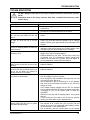
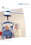
USER MANUAL Revision 1, December 2002 É IMPORTANT: Read these instructions before installing, operating or servicing this system. V4 ® CEILING LIFT SYSTEM DO NOT DESTROY KEEP THIS MANUAL WITH THE LIFT AT ALL TIMES. BHM MEDICAL INC., 2001 TANGUAY STREET, MAGOG, QUEBEC, CANADA, JIX 5Y5 Instruction manual Part # 001.14005 . BHM . Medical Inc. designs and manufactures quality engineered patient lifting equipment for the care of the disabled in hospitals, nursing homes and home care. Please take the time to read the entire manual, including the section on Safety Instructions and Warnings. It contains important information that will allow you to take advantage of all the characteristics of your BHM patient lift. BHM Medical Inc. Credentials • FDA Registration # 9681684 • CE mark (European Union Listing) • Global operations for in-warranty and out-of-warranty service support for V4 lift. • Each finished V4 is individually tested in our laboratory. • Lifting capacity is 190 kg (420 lb.). Engineering safety factor exceeds European Standards. • Complete range of patient lift slings and supports designed and manufactured by BHM Medical Inc. using medical quality materials and fabrics. • ISO 9001 • Voyager is a registered trademark of BHM Medical inc. APPROVALS: CSA 601.1 UL 2601.1 EN 60601.1 EN ISO 10535 (Lifting device) SGS UK Test Report: DUR22107/AC/OO Note: BHM Medical is constantly improving its products. For this reason, it may be possible to encounter a modification of product without revision of this guide. Thank you for trusting your BHM Medical Partners. How to contact us: North America: BHM Medical Inc. 2001 Tanguay Street Magog (Quebec) Canada J1X 5Y5 Phone: (819) 868-0441 Service calls during business hours - extension #109 (8:00-12:00 and 1:00-5:00 p.m. E.S.T.) Service calls outside regular business hours extension #6199 (you must press the pound key) Fax: (819) 868-2249 Web site: www.bhm-medical.com E-mail: [email protected] V4 CEILING LIFT 2 TABLE DES MATIÈRES INTRODUCTION ........................................................................................................................................... 4 How to use this Manual.............................................................................................................................. 4 Equipment Identification ............................................................................................................................ 4 Receipt of Equipment................................................................................................................................. 4 Key to Symbols .......................................................................................................................................... 4 SAFETY INSTRUCTIONS AND WARNINGS .............................................................................................. 6 DESCRIPTION OF EQUIPMENT – V4 ......................................................................................................... 8 Lift Unit....................................................................................................................................................... 8 What’s included.......................................................................................................................................... 8 Dimensions ................................................................................................................................................ 8 Part description .......................................................................................................................................... 9 BHM ERGOFIT SLING ............................................................................................................................... 10 Hammock Sling........................................................................................................................................ 10 Sling Attachment Options ........................................................................................................................ 12 Quick-Fit Sling.......................................................................................................................................... 15 Hygienic Sling .......................................................................................................................................... 17 Walking Sling ........................................................................................................................................... 18 OPERATION ............................................................................................................................................... 21 How to use the V4.................................................................................................................................... 21 Emergency Stop (Red Cord) ................................................................................................................... 21 Emergency Lowering Feature.................................................................................................................. 22 Emergency Brake .................................................................................................................................... 22 Battery Information................................................................................................................................... 22 Indicator Lights......................................................................................................................................... 23 Charger Specifications............................................................................................................................. 24 Programming the Lift................................................................................................................................ 24 MAINTENANCE .......................................................................................................................................... 25 Daily Check List ....................................................................................................................................... 25 Inspection and Cleaning .......................................................................................................................... 25 Strap Inspection ....................................................................................................................................... 25 Handling and Storage .............................................................................................................................. 26 Battery Replacement ............................................................................................................................... 26 Sling Inspection and Care........................................................................................................................ 26 Annual Inspection .................................................................................................................................... 27 Maintenance Requirements..................................................................................................................... 27 MAINTENANCE INSPECTION CHECKLIST ............................................................................................. 28 TROUBLESHOOTING ................................................................................................................................ 29 ACCESSORIES .......................................................................................................................................... 31 LOGBOOK .................................................................................................................................................. 32 WARRANTY................................................................................................................................................ 35 V4 CEILING LIFT 3 INTRODUCTION Equipment Identification INTRODUCTION How to use this Manual DO NOT ATTEMPT TO USE THIS EQUIPMENT WITHOUT UNDERSTANDING THIS MANUAL. To ensure safe operation, read the entire manual carefully, especially the section on “Safety Instructions and Warnings”, before installing, operating, or servicing this equipment. If anything is not completely understood, please contact your supplier for more details. Failure to comply with warnings in this manual may result in injury. Keep this manual with the lift and refer to it as required. Contents of this manual are subject to change without prior notice to users. The unit's identification number (specification, model, serial number) appears on a silver nameplate attached to the back of base. Receipt of Equipment Upon receipt of the equipment, verify it against the packing list to ensure it is complete and inspect the equipment for possible damage due to shipping. If there is any damage, DO NOT USE the equipment and notify the carrier immediately to file a claim. Provide complete information concerning damage claims or shipping errors to your supplier. Include all equipment identification numbers and group part numbers (if any) as described above along with a full description of damaged parts. Key to Symbols The following symbols are used on the V4 lift: This symbol indicates the power-on indicator. Throughout this manual, the following symbols may appear. Pay particular attention to the information provided under these headings. These special annotations are easily recognised as follows: WARNING: intended to hazards or which could bodily harm. This symbol indicates the charging indicator light. The symbol indicates the light "Service". This symbol represents the emergency stop. this symbol is alert the user to unsafe practices, result in serious The following symbols are used on lifter’s attachment labels: This symbol is required to be displayed on regulated products for sale in the European Market. It indicates that the product complies with applicable European Directives related to health, safety and environment, and consumer protection. CAUTION: this symbol is intended to alert the user of the presence of important operating and maintenance instructions, which could prevent product damage or possible personal injury. NOTE: this symbol offers helpful information concerning certain operating procedures. You can purchase additional copies of this manual by contacting your supplier. Include the User Manual product number and equipment identifcation number. SWL Safe Working Load represents the maximum load the lifter is rated for safe operation. The following symbols are used on sling labels and related to washing instructions: 60ºC Maximum washing temperature is 60°C (140°F) permanent cycle. Do not use bleach. Do not dry clean. V4 CEILING LIFT 4 INTRODUCTION Tumble dry low temperature. Do not iron. Please refer to individual sling labels for complete instructions regarding washing and drying. V4 CEILING LIFT 5 SAFETY INSTRUCTIONS AND WARNINGS SAFETY INSTRUCTIONS AND WARNINGS A. GENERAL ¾ IMPORTANT – READ THESE INSTRUCTIONS CAREFULLY OR SERIOUS INJURY MAY RESULT. ¾ KEEP THESE INSTRUCTIONS AND THE KEY PROVIDED WITH THE LIFT AT ALL TIMES. ¾ READ OPERATION AND MAINTENANCE INSTRUCTIONS IN THIS MANUAL BEFORE INSTALLING, OPERATING, OR SERVICING THIS EQUIPMENT. ¾ BHM Medical ceiling lifts must be installed by an authorised contractor or installer. ¾ YOUR LIFT is for transferring patients only. Do not use the lift for any other purpose. ¾ ALWAYS carry out the daily checklist before using the lift. ¾ BHM Medical ceiling lifts are specifically designed for BHM Medical ceiling rail systems, slings and accessories. Slings and accessories designed by any other manufacturer are prohibited and will void BHM Medical’s warranty. Use only BHM Medical slings and accessories to maintain patient safety and product utility. ¾ BHM Medical ceiling lifts are intended to be used for patients within the specified weight limit indicated for the lift. Do not attempt to lift more than the weight limit indicated. ¾ Before attempting to transfer, the patient must be assessed by a qualified professional. ¾ BHM Medical ceiling lifts must be used by a caregiver with proper training to work with the patient to be transferred. ¾ ONLY trained and qualified caregivers should transfer a patient. DO NOT attempt to use the lift if you have not been properly trained to do so. ¾ ALWAYS be prepared before attempting to transfer a patient. ¾ DO NOT use a sling that is not recommended for the lift. ¾ NEVER use a damaged, torn or frayed sling. ¾ ALWAYS place the sling around the patient according to the instructions enclosed. ¾ FOLLOW lifting procedures outlined in this manual. ¾ USE all controls and safety features only according to the rules specified in this manual. Never attempt to force a control or button on the lift. ¾ DO NOT store the charger in a shower, bath or other areas with high humidity. ¾ DO NOT drop the patient lift or batteries. Dropping the lift or batteries may cause internal damage that is not easily seen. If lift is suspected to be damaged, take to an authorised technician for servicing. ¾ IMPORTANT: Keep all components of the lift clean and dry, and have electrical and mechanical safety checkpoints done as instructed in the Maintenance section of this manual. ¾ Replace any precautionary or instruction labels that cannot be easily read. ¾ Avoid violent shock during transportation. B. SHOCK PREVENTION ¾ DO NOT touch or use a lift with bare conductors or a damaged power cord. Electrically live equipment can electrocute a patient. If the lift or charger has any exposed or damaged wires contact your local dealer imm ¾ DO NOT splash or expose electric parts of the device to water or moisture. ¾ CHECK nameplate for voltage and cycle requirements. These requirements differ by country. Do not attempt to use the lift in an area that has a different voltage and cycle requirement. V4 CEILING LIFT 6 SAFETY INSTRUCTIONS AND WARNINGS ¾ DO NOT attempt to expose, service or repair the lift, battery or charger. malfunctioning, contact your local dealer. If any unit is ¾ READ batteries and charger instructions thoroughly before using or storing them. C. FIRE AND EXPLOSION PREVENTION ¾ ¾ Batteries may explode, leak and cause personal injury if not disposed of properly. • Do not place or store the battery under direct sunlight or near a heat source • Do not dispose of in fire • Do not short the battery terminals • Do not incinerate • Flush with water if electrolyte (Acid) comes in contact with skin or eyes. Batteries must be recycled, disposed of according to local law regulations. When returning batteries, insulate their terminals with adhesive tape, etc. Otherwise, the residual electricity in used batteries may cause fire or explosion. D. EQUIPMENT WARNING LABELS ¾ INSPECT all precautionary labels on the equipment. Order and replace all labels that cannot be easily read. V4 CEILING LIFT 7 DESCRIPTION OF EQUIPMENT Lift Unit The lift unit is a steel frame based system driven by a gear reduced high torque motor. OPERATING FEATURES: • Lifting capacity: 190 kg (420 lb.). • Average weight: 11.5 kg (28 lb.) batteries included. • Electronic soft-start and soft-stop motor control. • Emergency lowering device. • Emergency stopping device. • Current limiter for circuit protection in case of overload. • Safety device that stops the motor to lift when batteries are too low. • Lifting speed: 6 cm/s (2.3 in/s.), 3.5 cm/sec. (1.6 in/s.) in full capacity. • Horizontal displacement speeds: 10, 15, 20 and 25 cm/s. Speed by default 20 cm/s. (6 in/s.). • Horizontal axis motor: 24 VDC at 62 watts and vertical axis motor at 110 w. • Ermergency brake (in case of mechanical failure). Operates on the same principle as a car safety belt mechanism • Strap length up to 2.3 m (90 inches) tested for 1360 kg (2998 lb.). • CSA No 601.1, UL No 2601-1 and CE certifications. • Respect EMI standards • ISO 10535. V4 CEILING LIFT What’s included ITEM QTY V4 lift 1 Batteries (inside unit) 2 Clip on charging station 1 Handset 1 Carry bar 1 Power cord 1 8-mm Alllen key 1 User Manual 1 Dimensions (in millimeters) CEILING (STROKE) DESCRIPTION OF EQUIPMENT – V4 8 DESCRIPTION OF EQUIPMENT Part description Door Charging station Manual lowering Rail Charger Lift 8-mm Allen key Strap Carry bar On green light Handset Charger yellow light Red light for service Left Up button Right Down Down button Red cord for emergency stop Up Programming mode (PROG) Return to charge Notes: - the yellow light "charger" flashes while charging and illuminates when charge is finished; the green light "on" illuminates once the lift is on and ready for use; the green light flashes when the batteries are low. The red light "service" flashes when servicing is required (contact customer service); The button "Programming mode" allows you to modify the functions of the product. V4 CEILING LIFT 9 BHM SLING the sling during a transfer. BHM ERGOFIT SLING Every patient has different needs. It is very important to choose the right sling based on the needs of the patient to be transferred as well as their physical ability and size. All BHM slings are made from a Polyester/ Nylon material, which is soft and pliable, easy to care for, and install. All slings are machine wash and dry on medium temperature. BHM slings are covered by a one-year warranty. PLEASE READ THE FOLLOWING CAREFULLY, BEFORE USING A BHM MEDICAL ERGOFIT SLING. ¾ ALWAYS CARRY OUT THE DAILY CHECKLIST BEFORE EACH LIFT USE. ¾ BHM MEDICAL CEILING LIFTS ARE SPECIFICALLY DESIGNED FOR BHM MEDICAL SLINGS AND ACCESSORIES. SLINGS AND ACCESSORIES DESIGNED BY ANY OTHER MANUFACTURER ARE PROHIBITED AND WILL VOID BHM MEDICAL’S WARRANTY. USE ONLY BHM MEDICAL SLINGS AND ACCESSORIES TO MAINTAIN PATIENT SAFETY AND PRODUCT UTILITY. ¾ PATIENT TO BE TRANSFERRED MUST BE ASSESSED BY A QUALIFIED PROFESSIONAL BEFORE ATTEMPTING TO TRANSFER. Observe a trained expert to perform the transfer procedures and then practice them several times with a capable individual acting as patient before attempting a transfer with a patient with limited capabilities. ¾ READ CAREFULLY ALL INSTRUCTIONS BELOW BEFORE ATTEMPTING TO INSTALL A SLING. ¾ IF YOU HAVE ANY DOUBTS, PLEASE CONTACT YOUR REPRESENTATIVE. LOCAL ¾ USE A SLING RECOMMENDED BY THE PATIENT’S PHYSICIAN, NURSE OR MEDICAL SPECIALIST AS APPROPRIATE FOR THE PATIENT’S ABILITY AND NEEDS. DO NOT exceed the maximum weight limitation of the sling. ¾ WHENEVER POSSIBLE, HAVE SOMEONE ASSIST YOU TO ENSURE THE PATIENT’S SAFETY AT ALL TIMES. Laundry Instructions for all slings: The following symbols are used on sling labels and related to washing instructions: 60ºC Maximum washing temperature is 60°C (140°F) for permanent cycle. Do not use bleach. Do not dry clean. Tumble dry low temperature. Do not iron. User instructions for: Hammock Sling Inspect each sling for wear, tears or loose stitching after each wash. Hammock Sling (THA-S, M & L) Our most universal sling, the Hammock sling, is a mesh type material that dries quickly but is soft and pliable. The sling has an incorporated head support and a unique strap system that keeps the patient secure in the sling. A special polyester fabric in the seat area helps to reduce friction and makes the sling easy to place around a patient in a chair without lifting or removing the patient. The patient may be transferred in a seated, semi-reclined or fully reclined position. Best choice for most situations – including bathing. Fits all BHM ceiling lift models as well as the Ergolift Mobile Lift. Available in sizes S, M & L. Weight capacity is 250 kg (550 lb.). DO NOT use any kind of plastic backed incontinence pad or seating cushion between the patient and sling material. This may cause the patient to slide out of V4 CEILING LIFT 10 BHM SLING Hammock 6 Strap Sling (THA6-S, M & L) Almost identical to the Hammock sling above, this sling provides extra security and a tighter fit for patients who are low-tone or who would prefer a more secure feeling. The head support is tighter and the extra straps on the side provide more lateral support. The patient may be transferred in a seated, semi-reclined or fully reclined position. Fit all BHM ceiling lift models as well as the Ergolift mobile lift. Available in sizes S, M & L. Weight capacity is 250 kg (550 lb.) (U-shaped and white fabric) 2. Lean the patient forward in the chair and make sure that the patient is supported. Whenever possible have someone assist you to ensure the patient's safety at all times. 3. With the white fabric of the sling facing the patient, grab the sling at the top of the Ushape and slide the sling down to the base of the spine or coccyx. SLING SIZES AND PRODUCT NUMBERS: Approximate weight: Approximate height: Color Code Hammock Product # Hammock 6 Product # SMALL 20-46 kg (45-100 lb.) 120-150 cm (4’4’11”’) Red THA-S MEDIUM 46-95 kg (100-210 lb.) 151-180 cm (5’-5’11”) LARGE 95-250 kg (210-550 lb.) 181 cm + (6’ +) Yellow THA-M Green THA-L THA6-S THA6-M THA6-L Sling Placement - from Chair or Wheelchair 4. Tuck the sling down on each side to make sure that it is just slightly under the patient’s buttocks. Check for the stitching of the sling handle at the center to make sure that it is in line with the patient’s spine and bring the patient to the back of the chair or wheelchair. 1. Sling has two sides, the white fabric indicates the side that is intended to be next to the patient, the label and colored handles are on the outside. The top of the sling is slightly rounded and the bottom of the sling has a Ushaped design. V4 CEILING LIFT 11 BHM SLING Option 1 - Bridge (Most recommended) a) Take the two straps between the legs – these are the short loops – and thread one loop through the other to cross them. b) Now take the long strap on the outside of each leg and string it through the inside strap. By crossing the straps as you see here, form a bridge above the patient’s legs and protect them from any pinching or pressure, as well as keep the knees and hips in line. c) Finally, place the patient’s hands inside the sling. 5. Kneel in front of the patient so that your back is straight and so you are at eye level with the patient. Grab the end of the sling with the white fabric and make sure there are no twists in the sling. Make sure the white fabric is facing the patient’s leg. Place one hand on the patient’s knee to hold it in place and gently pull the sling forward with the other hand until the edge of the sling is approximately even with the patient’s knee. 6. Place the patient’s foot on your thigh and slide the white section of the sling under the leg. OPTION 2 – Leg Separation 7. Repeat steps 5 & 6 for the other leg. Sling Attachment Options Using this method of sling placement will pull the patient’s legs apart. Check with the patient’s physician, nurse or medical specialist before attempting this method. a) Thread the long strap through the short strap on each leg. V4 CEILING LIFT 12 BHM SLING a) Slide the sling end with the white fabric so that it is all the way under both legs. One sling strap will be on top of the other. b) Each short strap should be looped through the long strap on the same leg. c) Place the hands inside the sling. See sling placement for leg separation as installed below. b) Thread the long strap through the short strap that is next to it. The photo below shows clearly an example without a patient in it. c) When installed there should not be any sling material between the patient’s legs. Place the hands inside the sling. Sling Placement- from lying position 1. Fold the sling in half lengthwise with the white part of the sling on the inside of the fold and place next to the patient to be transferred. OPTION 3 – Amputee Do not use this method of sling placement for a patient who is agitated or spastic. V4 CEILING LIFT 13 BHM SLING 3. Lower the patient down on top of the sling. Roll the patient the opposite direction to pull the sling out the other side. When transferring a patient from a bed, have people on each side of it, or raise the bed rails to ensure the patient does not roll off the bed. 2. With someone there to assist you, carefully roll the patient onto one side. Now place the fold of the sling at the center of the bed or where the spine of the patient will be. The top of the U-shape in the sling should be at the base of the spine or coccyx .The top of the sling should be next to the head. Lift the top fold and tuck next to the patient. 4. Place the straps in the same way as shown from a seated position for the hammock sling. Sling attachment to Carry Bar 1. Ensure the sling is properly placed around the patient according to the instructions above. 2. Choose the colour of the loop you will need for the position you will be placing the patient in. If transferring to a seated position, use the loops indicating it. V4 CEILING LIFT 14 BHM SLING SLING SIZES AND PRODUCT NUMBERS: Approximate weight: Always use the same colour loop on the rear shoulder straps for both sides of the sling. Use the same colour loop on the leg straps for both sides of the sling. Use the same colour loop on the hip straps for both sides of the Hammock 6strap sling. 3. Ensure the patient’s arms are inside the sling and that it is not caught on any obstructions (e.g. Wheelchair brake or handle). 4. See Lift Instructions for next step. User Instructions for: Approximate height: Colour Code Quick-fit SMALL 20-46 kg (45-100 lb.) 120-150 cm (4’4’11”’) Red TIR-S MEDIUM 46-95 kg (100-210 lb.) 151-180 cm (5’5’11”) Yellow TIR-M LARGE 95-250 kg (210-550 lb.) 181 cm + (6’ +) Green TIR-L Sling Placement - from Chair or Wheelchair Whenever possible have someone assist you to ensure the patient's safety at all times. 1. Sling has two sides, the white fabric indicates the side that is intended to be next to the patient, the label and coloured handles are on the outside. The top of the sling is straight and the bottom of the sling has a U-shaped design. Quick-Fit Sling Specially designed for patients who are stocky or obese, especially in the midsection. Padding around the buttocks and leg area helps to provide extra support. Upper portion of the sling is a mesh type material that dries quickly but is soft and pliable. This sling does not provide head support. The patient may be lifted in a seated, semi-reclined or fully reclined position. Fit all BHM ceiling lift models as well as the Ergolift mobile lift. Available in sizes S, M & L. Weight capacity is 250 kg (550 lb.) Do not use the Quick-Fit sling on a patient who cannot support his or her own head. V4 CEILING LIFT 2. Lean patient forward in the chair and make sure the patient is supported. 3. With the white fabric of the sling facing the patient, grab the sling at the top of the Ushape and slide it down to the base of the spine or coccyx. Tuck the sling down on each side to make sure that it is just slightly under the patient’s buttocks. Check the seam for the sling handle at the center to 15 BHM SLING make sure that it is in line with the patient’s spine and bring the patient to the back of the chair. 4. Kneel in front of the patient so that your back is straight and so you are at eye level with your patient. Grab the end of the sling with the white fabric and make sure there are no twists in the sling. The white fabric should be facing the patient’s leg. Place one hand on the patient’s knee to hold it in place and gently pull the sling forward with the other hand until the edge of the sling is approximately even with the patient’s knee. 8. Place the patient’s hands inside the sling before attaching it to the lift. Sling attachment to Carry Bar 1. Ensure the sling is properly placed around the patient according to the instructions above. 2. Choose the colour of the loop you will need for the position you will be placing the patient in. If transferring to a seated position, use the loops indicated for a seated position. 5. Place the patient’s foot on your thigh and slide the white section of the sling under the leg. 6. Take the two straps between the legs. There is a small loop on each strap right next to the sling. Thread one strap through the other to cross them. Always use the same colour loop on the rear shoulder straps for both sides of the sling. 7. By crossing the straps as you see here, we keep the knees and hips in line. Use the same colour loop on the hip straps for both sides of the sling. 3. Ensure the patient’s arms are inside the sling and that it is not caught on any obstructions (e.g. Wheelchair brake or handle) 4. See Lift Instructions for next step. V4 CEILING LIFT 16 BHM SLING User Instructions for: Hygienic Sling This sling is excellent for changing incontinence pads or to transfer onto a toilet as it provides an open area from the middle of the back to the middle of the thigh. The padding wraps around the patient’s midsection and under each leg. In order to use this sling, the patient must have good muscle-tone in their shoulders and upper body. Fit all BHM ceiling lift models as well as the Ergolift mobile lift and Ergostand stand-assist. Available in sizes S, M & L. Weight capacity is 250 kg (550 lb.) Do not use Hygienic sling on a patient who does not have good muscle-tone in their shoulders and neck. Check with the patient’s physician, nurse or medical specialist before using this sling. Whenever possible have someone assist you to ensure the patient's safety at all times. 2. Lean patient forward in the chair and make sure the patient is supported. 3. With the white fabric of the sling facing the patient, place it approximately halfway down the back, or so the sling is below the shoulder blades. Lean the patient against the back of the chair. SLING SIZES AND PRODUCT NUMBERS SMALL MEDIUM LARGE CHEST SIZE 68-89 cm 89-107 cm 107-125 cm (27-35”) (35-42”) (42-49”) PRODUCT # THY-S THY-M THY-L COLOR CODE Yellow Green Red 1. Sling has two sides, the white fabric indicates the side that is intended to be next to the patient, label and colored handles are on the outside. The bottom of the sling has two long straps and the inside of the sling has a padded section with a belt. V4 CEILING LIFT 4. Fold the padded fabric waistband with the belt attached across the mid-section of the patient and clip the belt closed. Make sure the belt is secure. 17 BHM SLING 5. Tighten the belt until snug by pulling gently on the end of the belt. 6. Kneel in front of the patient so that your back is straight and so you are at eye level with the patient. Grab the end of the sling with the white fabric and make sure there are no twists in the sling. Make sure the white fabric is facing the patient's leg. Place the patient's foot on your thigh and slide the white section of the sling under the leg. Always use the same colour loop on the shoulder straps for both sides of the sling. Use the same colour loop on the leg straps for both sides of the sling. 3. Ensure the patient’s arms are over top of the sling and that it is not caught on any obstructions (e.g. Wheelchair brake or handle). 4. See Lift Instructions for next step. User Instructions for: Walking Sling 7. The hygienic straps need not cross to allow better access to the toileting area. With the hygienic sling, the arms of the patient are always over top of the sling. Sling attachment to Carry Bar 1. Ensure the sling is properly placed around the patient according to the instructions above. 2. Choose the colour of the loop for the position that is best suited for the patient. For a larger patient, choose blue for both the leg and shoulder straps. A smaller patient may be better suited for the black loops on both the shoulder and leg straps. V4 CEILING LIFT Designed to assist people with limited ability to walk, this sling helps support and assist in rehabilitation. Fully padded with a security buckle, the sling is comfortable and simple to use. The user must have some weight bearing ability. Fit all BHM ceiling lift models as well as the Ergolift mobile lift. Available in sizes S, M & L. Weight capacity is 250 kg (550 lb.). Do not use the Walking sling on a patient who does not have weight bearing ability and good muscletone in their shoulders and neck. Check with the patient's physician, nurse or medical specialist before using this sling. 18 BHM SLING SLING SIZES AND PRODUCT NUMBERS SMALL MEDIUM and clip the belt closed. Make sure the belt is secure. LARGE CHEST SIZE 68-89 cm 89-107 cm 107-125 cm (27-35”) (35-42”) (42-49”) PRODUCT # TEM-S TEM-M TEM-L COLOUR CODE Yellow Green Red 1. Sling has two sides, the white fabric indicates the side that is intended to be next to the patient and the label and coloured handles are on the outside. The bottom of the sling has two long straps and the inside of the sling has a padded waist section with a belt. Whenever possible, have someone assist you to ensure the patient's safety at all times. 2. Lean patient forward in the chair and make sure the patient is supported. 3. With the white fabric of the sling facing the patient, place the sling approximately halfway down the back, or so it is below the shoulder blades. Lean the patient against the back of the chair. 4. Fold the padded fabric waistband with the belt attached across the mid-section of the patient V4 CEILING LIFT 5. Tighten the belt until snug by pulling gently on the end of it. 6. Kneel in front of the patient so that your back is straight and so you are at eye level with the patient. Grab the end of the sling with the white fabric and make sure there are no twists in the sling. The white fabric should be facing the patient’s leg. Place the patient’s foot on your thigh and slide the white section of the sling under the leg. 7. The straps that come from between the legs do not attach to the lift. Thread the strap at the chest through the longest loop on the same side. 19 BHM SLING Always use the same colour loop on the rear shoulder straps for both sides of the sling. Use the same colour loop on the chest straps for both sides of the sling. 3. Make sure the patient’s arms are over top of the sling and that it is not caught on any obstructions (e.g. wheelchair brake or handle). 8. Repeat step 7 with the other side. 4. See Lift instructions for next step. 5. When raising the patient in the lift, check to make sure the sling sections between the legs are providing snug support. If there is not enough support, reinstall the sling threading the chest straps through a lower loop (grey or black). Repeat this step until the lower portion of the sling is provides proper support. 9. Note that with the walking sling, the arms of the patient are always over top of the sling. Sling attachment to Carry Bar 1. Ensure the sling is properly placed around the patient according to the instructions above. 2. Adjusting the sling loops higher or lower in either the front or the back allows you to tilt the body either direction to correct posture. V4 CEILING LIFT 20 OPERATION BEFORE LIFTING THE PATIENT: OPERATION 1. Make sure that all straps are attached to the carry bar. ; How to use the V4 2. Make sure the comfortable; READ « SAFETY INSTRUCTIONS AND WARNING" BEFORE ATTEMPTING TO USE THE V4. is 3. Make sure the sling is not caught on any obstruction (wheelchair brake or arm of the chair) V4 If any of the above occur – lower the patient immediately and correct the problem. The unit will not lift or lower when in contact with the charger. 1. Install the patient sling (see sling instruction). 2. Move the lift directly over the patient. Use the left and right buttons on the handset. Left patient Up right 3. Use the down button on the handset to lower the carry Down bar under the patient’s chin (to avoid the risk of facial contact caused by a sudden movement of the carry bar) before beginning to attach the sling straps. It the lift will not operate – pull red cord once gently, until you hear a click. If the lift does not work, gently pull on the red cord until you hear a click. The green light should illuminate. Note: In a laying down position, lower the carry bar near the thorax, then install the straps. Hold the lift carry bar with one hand at all times when near a patient 4. Attach the staps to the desired position. (See "Sling Instructions"). 5. Carefully observe the patient to ensure his/her safety as you press the control buttons. To lift the patient, press on the up button, 6. Make sure the patient is clear of any obstables before moving the patient. Guide the legs if necessary. 7. When the patient is located above the desired point of transfer, press on the down button. 8. Use the handles on the back of the sling to position the patient when transferring into a chair. Hold the handset firmly as the sling lowers and the sling will tilt back to position the patient. 9. Once the patient is properly seated and the straps are loose, remove the sling from the lift. Hold the lift carry bar with one hand at all times when near a patient. 10. Slide the lift away from the patient. 11. When the lift is no longer required, return the lift to the charger station by pressing on the return button. 12. The charging indicator light must be on for the lift to detect the Clip on charging station. Take note that the lift memorizes the charger station position. 13. Verify the green light at the charging station and the yellow light (flashing or light) of the lift to ensure that charge function is working properly. Emergency Stop (Red Cord) 1. The emergency stop can be activated at any time to stop the functioning of the lift. 2. To stop the lift in an emergency, pull on the red cord once gently, you will hear a "click". V4 CEILING LIFT 21 OPERATION 4. To lower your patient more rapidly, use a ratchet or a drill with an 8-mm Allen key. 5. Once the patient is lowered and secure on a chair or in a bed, call a qualified technician to inspect your lift. Emergency Brake • The emergency brake is made of a metal bar fixed to the drum • In case of a chain, gear or motor breakage, the centrifugal force created will block the bar against the frame. Do not pull red cord forcefully. If the cord is pulled too forcefully, the lift may become inoperable. To activate the lift, pull the red cord once gently. The green light confirms that the lift is on. Emergency Lowering Feature In the event of an electrical or functional failure, the V4 has an emergency manual lowering feature. Battery Information If the lift malfunctions when a patient is being transferred, the emergency lower device provides a safe way of lowering the patien onto a chair or a bed. 1. Remove the 8-mm Allen key on top of the lift. 2. Open the side mechanism. door to access the 3. Insert the Allen key deep into the gear, visible in the lateral door. Turn it counter clockwise in order to lower your patient. The key turns the main gear and each turn of the key will slowy lower your patient. V4 CEILING LIFT • • 2 rechargeable batteries of 12 Vdc, 5 Ah. Provides up to 120 transfers with a load of 74 kg (200 lb.) and up to 70 transfers with its’ maximum load of 190 kg (420 lb.). Life cycle (number of charging cycles) of the batteries is largely dependent on the depth of discharge in each cycle. More the batteries are drained, the shorter their life span. The life of the batteries is also related to such factors as varying temperatures and rest periods between charge and discharge. Graph 1: Number of recharges vs. Depth of discharge Capacité (%) de la Battery capacity batterie(%) Only to be used in case of an emergency. 100 80 30% 50% 100% 60 40 20 0 0 500 1000 1500 2000 2500 3000 Cycles de chargement Charge/discharge cycles/ déchargement Graph 1 illustrates the relationship between the discharging depth and expected battery life. 22 OPERATION If you drain the batteries until they beep every time, you can expect the batteries to fully charge only 600 times. To prolong battery life, return the lift to the charger WHENEVER THE LIFT IS NOT IN USE. BHM uses sealed lead-acid batteries. Contrary to nickel-cadmium, BHM batteries do not have any memory effect. Therefore, batteries should not be completely drained before recharge. Graph 2: Number of lifts vs. lift load Red light Maintenance ----------Maintenance required by your local representative Lift started by service mode. Charging indicator green light Clip on charging station indicator green light Turn on Charger on Turn on Clip on charging station on Charging the batteries DO NOT operate the charger unit with a damaged cord or if the unit has been dropped or damaged. Nombre de levée selon la charge soulevée Number of lifts vs Lift Load 200 Levées Number of lifts Charging done, batteries charged. DO NOT forcibly bend the power cord or place a heavy object on it. This will damage the cord and may cause fire or electrical shock. 150 100 50 0 0 50 100 150 200 DO NOT pour liquid on or near the charger.. Weight (lb) Never let a lift with the power on for a long period of time if you did not return the lift to the charger, otherwise batteries will be drained and damaged. Do not place the unit in locations that are: • Extremely hot • Dusty or dirty • Very humid • Moving or vibrating Do not drain the batteries excessively. This will dramatically reduce the life span of the batteries. If the low battery buzzer sounds and green light flashes, be sure to recharge the battery as soon as possible. Indicator Lights The lift and the charging system has many indicator lights. It important to understand their significance for use and comprehension of the lift. Green light Operating the lift ----------Low batteries The lift is on and ready to use. Yellow light State of batteries ----------In process of charging batteries V4 CEILING LIFT 23 OPERATION The recharging steps are as follow: Press the return to charger button on the handset. A protection device prevents the lift from returning to the charger with a load of more than 14 kg (30 lbs), approximately the weight « Prog » of the carry bar. 3. While holding the « PROG » button, pull on the red cord once again. 4. The green light will flash and the lift will beep three times. 5. Release the “PROG” button. «Return» DO NOT SLIDE THE LIFT TO THE CHARGER FORCEFULLY OR QUICKLY. CHARGER MAY BECOME DAMAGED. • • The green indicator light will begin flashing if batteries are low and need to be recharged. If the light does not illuminate, verify the « Trouble Shooting » section of this manual. The yellow indicator light will flash when the lift is returned to charger. This indicates that the batteries are being charged. Once the charge is complete the light will stop flashing and become a sold yellow light. Whenever possible, leave the lift on the charger when the lift is not in use. At minimum, charge the battery until the light is green before using it again. This will extend the life of the battery. If batteries have been completely drained it could take up to 6-8 hours to completely recharge them. In order to reduce charging time, refrain from completely draining the battereis and leave the lift on the charging station between uses. Charger Specifications • • Charger input: 100-240 Vac, 50/60 Hz. Charger output: 27 Vdc, 1 A max. 6. When the red light illuminates, this will confirm that the lift is in programming mode « Service ». The speed and height of the lift can be easily adjusted by the user while in the Program « Service » Mode. Use the “UP” button on the handset to select the parameters wanted. Each push of the button will bring you to a different selection: 1 beep = Speed displacement 2 beeps = Length of the strap To confirm your selection press once on the « PROG » button. B) Speed Adjustment 1. Enter into « Service» Mode and select the first choice. (Consult section A). 2. Use the « left » button on the handset to select the required speed as per selection chart below. Each push of the buttons allows you to go from one selection to the next. 1 beep 2 beeps 3 beeps 4 beeps 10 cm/sec 15 cm/sec 20 cm/sec 25 cm/sec 3. To confirm your choice of speed, press on the « PROG » button. 4. You can now choose a new selection by presssing on the “UP” button on the handset, if not turn off the lift and turn it back on by gently pulling on the red cord to return the lift to normal use. C) Adjust the height of the carry bar when it returns to charger 1. Choose the “Service” mode and select choice #2. (Consult section A). Programming the Lift 2. The strap will completely rewind. How to program the V4? 3. Once the carry bar is completely rewound, use the “UP” and “DOWN” buttons to position the carry bar to the desired height wanted when returning unit to charger. A) Enter into the « Mode Program » 1. Turn the lift off by pulling the red cord). (The green light must be turned off) 2. Press and hold down the “PROG” button on the handset (bottom left) V4 CEILING LIFT 4. To confirm the height desired, press on the “PROG” button. 24 MAINTENANCE 5. You can now choose a new selection by presssing on the “UP” button on the handset, if not turn off the lift and turn it back on by gently pulling on the red cord to return the lift to normal use. MAINTENANCE ALWAYS CARRY OUT THE DAILY CHECKLIST BEFORE EACH LIFT USE. Alterations made to the V4 by someone other than a certified technician may cause serious injury and voids the warranty. The V4 and accessories must be inspected ANNUALLY by a certified technician in addition to the daily and other periodic visual checks done by the user specified in this section. Preventive maintenance specified in this manual can prevent accidents and reduce repair costs. Note all service or repairs to the V4 or its accessories in the log book at the end of this manual. Have the document signed by the certified technician Daily Check List THE FOLLOWING PROCEDURES MUST BE FOLLOWED BEFORE EACH USE: • Have batteries been charged? Park the lift on the charger whenever the lift is not in use. • Inspect the lift for any damage. If the lift casing does not look properly aligned, or there are any cracks or other damage on the lift, or any parts are missing – DO NOT USE IT. Contact your local representative to have the lift serviced. • Inspect the visible strap for any signs of wear, frays, loose threads or other damage. If there is any evidence of damage – DO NOT USE IT. Contact your local representative to have the lift serviced. • Ensure the ring and cother pins that attach the carry bar to the strap are secure. Inspection and Cleaning Clean the V4 with a soft dry cloth, or a soft cloth lightly moistened with a mild detergent solution. Do not use any type of solvent that may damage the finish. Do not immerse lift in water. To ensure a better rolling surface for the trolley wheels, clean the inside of the track every 4 months. To do so, insert a damp cloth in the opening and slide it from one end of the track to the other. Always reinstall the rail end stopper (if they have been removed) after servicing. Strap Inspection This equipment is built with a strap that can withstand a load of 1364 kg (3000 lbs.) Nonetheless, if this strap is damaged or shows signs of wear, the acceptable load on the strap before rupture can drop rapidly and present a danger for the patient or caregiver. BHM Medical recommends thoroughly inspecting the strap every 2 months as follows: 1. Completely unwind the strap. 2. Look for any signs of wear: Loose threads in stitched area. Noticeable discoloration by having a Lighter color strap than the double thickness stitched area. Side wear. Middle wear. • Inspect the sling for tears, frayed straps or loose stitchings. If the sling has any of the above damage – DO NOT USE IT. Contact your local representative to have the sling replaced or repaired. If there is any sign of wear as indicated here or other visual defects, strap should be changed immediately. By continuing to use the lift without changing the strap, caregiver and patient safety is greatly compromised. • Inspect the carry bar for any signs of the cracking or damage. In any case, the manufacturer recommends changing the strap at least V4 CEILING LIFT 25 MAINTENANCE every two years. By continuing to use the lift without changing the strap, caregiver and patient safety is greatly compromised. 2. Make sure that there is contact between the contact plates of the lift and the circuit board of the charging station. 3. Check the power of the outlet. Take note of inspection results in the logbook at the end of this manual. 4. If the yellow or green light of the charging station do not light up, contact your local dealer or respresentative for assistance. Handling and Storage Avoid violent shock during transportation. The lift should not remain stored for long periods of time without recharging the batteries. BHM Medical recommends charging of batteries at least every two weeks even if the lift is not used. This will prevent premature aging of batteries. If you store or ship the V4 lift, turn the power off (green light off). Battery Replacement BHM uses sealed lead-acid batteries. Contrary to nickel-cadmium, BHM batteries do not have any memory effect. Therefore, batteries should not be completely discharged before recharge. Replace the battery when there is a noticeable reduction in the number of transfers that can be performed between charges. If you notice the Voyager lift “beeping” and a red light flashing, see the instructions in “Troubleshooting” to ensure it is a problem with the battery. To replace a battery, contact your local dealer or representative. DO NOT ATTEMPT TO USE A BATTERY NOT AUTHORIZED BY BHM MEDICAL. BHM batteries are specially designed for BHM charging systems. Attempting to use an unauthorized battery may seriously damage the lift and/or the charger. Sling Inspection and Care For maximum patient safety and hygiene, read the following instructions: Chemical Attack Oil, grease, creosote or paint stains are harmless but other forms of chemical attack of a sufficient degree may lead to deterioration or extreme softening of the webbing, which could lead to the fibres being rubbed off (almost as powder in extreme cases). It is best to avoid fumes, spray or mists of acid and alkalis or organic solvents. If contamination is suspected, wash out well in warm water. Avoid contact with excessive heat, which is likely to affect the product. Cleaning Certain chemical substances mentioned above may be removed with heavy duty cleaner diluted in warm water. Ensure that any cleaning agents are removed by rinsing thoroughly in warm water, maximum 60°C (140°F). For normal washing and cleaning, follow the care instructions on the label of the product. Storage Slings should be stored sunlight, stress, pressure, humidity. The sling should contact with sharp objects, possible damaging material. away from direct excessive heat or be kept away from corrosives or other Verification of Charger Power Source If the light does not illuminate when there are batteries in, do the following steps: 1. Make sure that the power cord is correctly plugged into the charger in the wall and Clip on charging station indicator green light is on. V4 CEILING LIFT Loose threads in stitched area. Noticeable discoloration by having lighter color strap than the double thickness stitched area. Side wear. Middle wear. 1. Check for any sign of wear on sling straps as described above and at the strap-sling junction. Buckles on certain slings should be 26 MAINTENANCE checked to ensure that the locking/unlocking mechanism opens and closes easily and is secure when locked. 2. Check for any sign of deterioration of the sling material. Check for general external wear, local abrasion, cuts, holes or burns in the webbing and for chemical attack. 3. Look at "stitched areas" for broken, worn, pulled or unravelled stitches. 4. Sling should be cleaned as indicated on the tag. If there is any sign of wear or deterioration as indicated above or other visual defect, sling should be changed immediately. By continuing to use the lift without changing the sling, care giver and patient safety is greatly compromised Take note of inspection results in the log book at the end of this manual. Annual Inspection The V4 and its accessories must be inspected annually by a certified technician. V4 AND ACCESSORIES MUST BE SERVICED EVERY 12 MONTHS AS A MINIMUM REQUIREMENT. Do not attempt to do the inspection unless you are certified to do so. As part of the annual inspection, an annual load test with the safe working load must be performed on the V4 as required for CE MARK MAINTENANCE. After annual inspection, have the logbook signed by the certified technician. Maintenance Requirements The V4 is equipped with an electronic monitor. This light will flash when a maintenance inspection is necessary to ensure the durability of the unit and the security of the patient and user. Once this light begins to flash please contact your local dealer/representative in order to perform the necessary maintenance inspection requirements. V4 CEILING LIFT 27 MAINTENANCE INSPECTION CHECKLIST MAINTENANCE INSPECTION CHECKLIST TO BE INSPECTED BY USER ITEM INITIALLY BEFORE EVERY USE X X EVERY 2 MONTHS EVERY 4 MONTHS EVERY YEAR EVERY 2 YEARS LIFT DEVICE Inspect for missing hardware or brocken panel. Inspect strap for wear. X Recharging batteries. X X X Inspect the carry bar on the strap of the lift for damage or cracks. X Inspect wheels in rail for damage, rust or cracks. Replace if damaged.. X Clean the rail and the Clip on charging station contacts. X Overall inspection by authorised personnel. X SLING AND HARDWARE Check all sling attachments for sign of wear. X Inspect sling material for wear or deterioration. X Inspect sling straps for wear. X Inspect for any defects or loose threads in the "stitched areas". X Cleaning sling as indicated on the tag. When necessary Verify emergency stop cord X Verify emergency lowering device. X MAINTENANCE BY A CERTIFIED TECHNICIAN Replace strap X Inspect the welding aspect on the frame to detect cracks X Inspect sprockets for wear. X Inspect connecting joints for proper attachment X Verify the emergency brake on the drum is turning freely. X Verify emwergency devices for good functioning. X Load test with the SWL (maximum working capacity) X Maintenance inspection points are suggested by the manufacturer, however in certain cases, some inspections should be done on a more frequent basis. By continuing to use the lift without replacing the listed parts in this maintenance inspection checklist, caregiver and patient safety is greatly compromised. V4 CEILING LIFT 28 TROUBLESHOOTING TROUBLESHOOTING DO NOT attempt to open the V4 lift. Only a certified technician is autorised to open the V4 lift. Alterations made to the V4 by someone other than a certified technician may cause serious injury. PROBLEMS The red light « Service » is on. TO CHECK • Contact your supplier or your local representative to do the maintenance. The unit starts and stops repetitively. • If the load is over the safe working load, the unit will not work due to an overload protection on the motor. The lift emits a "beep" during utilisation. • Batteries are low. Return the lift to the Clip on charging The unit may stop lifting but can still station. lower it. Charge indicator on the lift (yellow) does • Is the Clip on charging station is plugged into a standard not light up when the lift is on the outlet? If so, does the outlet have power? Clip on charging charger. station indicator green light confirms the functionality of the charger. When returning to charge, the lift passes • Clean the contact blades of the charging station with mild the Clip on charging station or takes the detergent. Pass the lift through the charging station once wrong direction. manually, then retry the automatic return to charger. Batteries are always dead after a few • Verify the functioning of the lift charger and the contact transfers (3 to 5). fingers on the Clip on charging station. • Replace batteries by new ones. The life of the current one is probably over. It is important to always change both batteries at the same time. (Contact your local dealer or your representative to have batteries replaced) The light on the charger shows a solid • Contact your local dealer or representative to have yellow yet the lift will only do one or two batteries replaced. transfers. The light on the charger shows yellow • Contact your local dealer or representative to have yet the lift will only work when there is no batteries replaced. one on the lift. When you attempt to transfer someone, the lift stops. The lift does not work when you press • Is the charger light is on? The lift must be moved away the buttons on the handset. from the charger in order to operate. . • Is the emergency stop activated? Gently pull the red cord once until the green light is on. • Are the buttons on the lift functioning? If so, the problem may come from the handset connection. If not, check the charge on the lift. • Is the hadset properly plugged into the lift? The handset may be slightly pulled out its socket yet appear as though it is plugged in. Pull out the plastic cover to check the connection. • Slide the lift over the Clip on charging station. Is the yellow light on? • If, after testing all of the above, the lift will not operate, contact your local dealer or your representative. The charging light on the lift remains • If available, try another integrated Clip on charging station flashing yellow and does not turn yellow from another lift or a spare one; plug it into the rail and after and overnight charge. charge for 3 hours. If the yellow light is still flashing, contact your local dealer or your representative. • Use a voltmeter, test two contact points on the charger V4 CEILING LIFT 29 TROUBLESHOOTING PROBLEMS TO CHECK (See diagram T-1). The voltmeter should read between 2630 volts AC. • Contact your local dealer or your representative. When you press the button to return the • Charger either does not have power or is not working lift to its charger (4-way motor only), the properly. See "Troubleshooting" question above. lift goes past the charger. DIAGRAMME T-1 26-30 Vdc V4 CEILING LIFT 30 ACCESSORIES ACCESSORIES CHARGER AND CLIP ON CHARGING STATION Product #700.15500 RAIL STOPPER Product #700.05430 CARRY BAR Product #700.05490 ERGOSCALE WEIGHING DEVICE Product #700.14800 TRAPEZE BAR Product #A5700 HANDSET FOR V420 PLUS 6-buttons - Product #700.13650 V4 CEILING LIFT 31 LOGBOOK LOGBOOK Product Name : V4 Product Serial Number : Date of purchase : Warranty Period : Distributed By : Owner Checklist : • • • • • Ensure the lift is serviced regularly as per he Maintenance Inspection Checklist on page 28. Contact an authorised BHM Medical Distributor / Service Agent immediately if there are any problems with the operation of the device. Ensure the logbook is completed and signed. Record any repairs required. Withdraw the patient lifter from service if inspection reveals that user safety is jeopardised in any way from use of the patient lifter. TO BE COMPLETED AFTER EACH SERVICE OR INSPECTION Service Type Pre-delivery Periodic inspection Minor Major Condition report : Action taken : Date : Inspected by: _________________ Service Type Pre-delivery ____________________ ____________________ Printed Signature Periodic inspection Minor Major Condition report : Action taken : Date : Inspected by: _________________ V4 CEILING LIFT ____________________ ____________________ Printed Signature 32 LOGBOOK Service Type Pre-delivery Periodic inspection Minor Major Condition report : Action taken : Date : Inspected by: _________________ Service Type Pre-delivery ____________________ ____________________ Printed Signature Periodic inspection Minor Major Condition report : Action taken : Date : Inspected by: _________________ Service Type Pre-delivery ____________________ ____________________ Printed Signature Periodic inspection Minor Major Condition report : Action taken : Date : Inspected by: _________________ Service Type Pre-delivery ____________________ ____________________ Printed Signature Periodic inspection Minor Major Condition report : Action taken : Date : Inspected by: _________________ V4 CEILING LIFT ____________________ ____________________ Printed Signature 33 LOGBOOK Service Type Pre-delivery Periodic inspection Minor Major Condition report : Action taken : Date : Inspected by: _________________ Service Type Pre-delivery ____________________ ____________________ Printed Signature Periodic inspection Minor Major Condition report : Action taken : Date : Inspected by: _________________ Service Type Pre-delivery ____________________ ____________________ Printed Signature Periodic inspection Minor Major Condition report : Action taken : Date : Inspected by: _________________ Service Type Pre-delivery ____________________ ____________________ Printed Signature Periodic inspection Minor Major Condition report : Action taken : Date : Inspected by: _________________ V4 CEILING LIFT ____________________ ____________________ Printed Signature 34 WARRANTY WARRANTY This warranty is extended only to the original purchaser/user of BHM products. BHM Medical Inc. warrants its products to be free from defects in material under normal use and service, within the periods stated below from the date of purchase. If within such warranty period any such product shall be proven to be defective, such product shall be repaired or replaced at BHM Medical’s option. This warranty does not include any labor or shipping charges incurred in replacement part installation or repair of any such product. BHM Medical’s sole obligation and your exclusive remedy under this warranty shall be limited to such repair and/or replacement. Patient Lifter Tracks and installation Weighing Devices Accessories on Lifter Slings Batteries - Voyager Portable Batteries - All other lifts Easytrack System 1 year Life time warranty* 1 year 1 year 1 year 3 months 1 year 1 year For warranty service, please contact the dealer from whom you purchased the BHM Medical product. [In the event that you do not receive satisfactory warranty service, please contact BHM Medical (see contact information in Table of Contents).] Do not return products to our factory without prior authorisation. BHM Medical will issue a Return Merchandise Authorisation (RMA) Number. C.O.D. shipments will be refused; all shipments to BHM Medical must be prepaid. For this warranty to be valid, the purchaser must present its original proof of purchase at the moment of the claim. The defective unit, assembly or part must be returned to BHM Medical for inspection. The part or components repaired or replaced are guaranteed for the remaining period of the initial warranty. Limitations and Exclusions: The warranty above does not apply to serial numbered products if the serial number has been removed or defaced. No warranty claim shall apply where the product or any other part thereof has been altered, varied, modified, or damaged; either accidentally or through improper or negligent use and storage. Warranty does not apply to products modified without BHM Medical’s express written consent, (including but not limited to products modified with unauthorized parts or attachments); products damaged by reason of repairs made to any component without the specific consent of BHM Medical, or to products damaged by circumstances beyond BHM Medical’s control. BHM Medical will solely determine evaluation of warranty claim. The warranty does not apply to problems arising from normal wear or failure to adhere to the instructions in this manual. BHM Medical Inc. slings are void of warranty if not laundered as per instructions on the Sling Label. BHM Medical Inc. shall not be liable for damages losses or inconveniences caused by a carrier. This warranty replaces any other warranty expressed or implicit and constitutes BHM Medical Inc. only obligation towards the purchaser. BHM Medical shall not be liable for any consequential or incidental damages whatsoever. * Valid only if BHM Medical did the original installation. Warranty voids if tracks/installation have been modified. V4 CEILING LIFT 35