Transcript
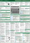
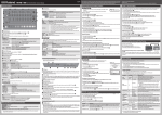
Owner’s Manual
English
*
5
1
0
0
0
4
4
3
3
3
-
0
1
Before using this unit, carefully read leaflet “USING THE UNIT SAFELY” . After reading, keep the
document(s) including those sections where it will be available for immediate reference.
Copyright © 2015 ROLAND CORPORATION
All rights reserved. No part of this publication may be reproduced in any form without the
written permission of ROLAND CORPORATION.
*
Rear Panel
[POWER] switch
DC IN jack
USB HOST (1–4) ports
USB (O) port
MIDI (IN, OUT) connectors
INPUT (1–4, 5/6) jacks
This turns the power on/off.
Connect the included AC adaptor here.
** To prevent the inadvertent disruption of power to your unit (should
the plug be pulled out accidentally), and to avoid applying undue
stress to the jack, anchor the power cord using the cord hook, as
shown in the illustration.
Use a commercially available USB 2.0 cable to connect this
port to your computer. It can be used to transfer USB MIDI
and USB audio data. You must install the USB driver before
connecting the MX-1 to your computer. Download the USB
driver from the Roland website. For details, refer to Readme.
htm which is included in the download.
For connecting MIDI device.
** When powering-on your equipment, you must turn on each device
in the following order: devices connected to the input jacks&the
MX-1&devices connected to the output jacks. Failure to observe
this order could cause malfunctions or damage your equipment.
When powering-off your equipment, you must turn off each device
in the following order: devices connected to the output jacks&the
MX-1&devices connected to the input jacks.
These are dedicated USB audio input ports for use only with
AIRA products (such as the TR-8, TB-3, VT-3, and SYSTEM-1). By
using commercially available USB 2.0 cables to connect your
AIRA products, you can input their audio output (stereo) to
the MX-1 and mix the audio outputs. The USB HOST 3 port can
supply USB bus power. The TB-3 or VT-3, which support bus
power, can be connected here.
Connect external sound sources to these jacks. By switching
their settings, you can use INPUT 1–4 jacks either as monaural
inputs (1, 2, 3, 4) or as stereo inputs (1/2, 3/4). INPUT 5/6 jacks
support stereo input.
Cord hook
** Before turning the unit on/off, always be sure to turn the volume
down. Even with the volume turned down, you might hear some
sound when switching the unit on/off. However, this is normal and
does not indicate a malfunction.
** Do not connect any USB device other than an AIRA
product.
The cord of the
supplied AC adaptor
** This unit is equipped with a protection circuit. A brief interval (a few
seconds) after turning the unit on is required before it will operate
normally.
DIGITAL IN/OUT jack
A two-channel (stereo) digital input/output device can be
connected here. Switch the setting of this jack between input/
output depending on the device that you connect.
** Do not use connection cables that contain a built-in resistor.
MIX OUT (L/MONO, R) jacks
Pro duc t S upp o r t
AUX SEND (L, R) jacks
http://www.roland.com/support/
These jacks output the send audio to an external effect unit.
Connect your amp or monitor speaker here. These jacks
output the master audio.
** The master audio is not output.
** Do not use connection cables that contain a built-in resistor.
AUX RETURN (L, R) jacks
PHONES jack
These jacks input the return audio from an external effect unit.
Connect headphones here.
Pro duc t S up p or t
http://www.roland.com/support/
PHONES
Effect Section
This adjusts the headphone output. The headphones let you listen to the master audio simultaneously with the sound of the
channel selected by the [SELECT] button. Even if you lower the level of the selected channel or mute it, you can listen to its sound
by turning the [MIXING] knob to the SELECT position; this lets you prepare the next song or make settings for it.
The effect section contains BEAT FX which lets you modify the sound by applying an effect to each channel, and MASTER FX
which applies an effect to the mixed sound of all channels.
[LEVEL] knob
[MIXING] knob
Select the steps at which the BEAT FX and MASTER FX are applied.
This adjusts the volume of the headphones.
The balance adjusted by the [MIXING] knob is output without
further change.
This adjusts the balance between the master output and
the channel whose [SELECT] button is lit. Turning the knob
toward SELECT decreases the volume of the master output;
turning the knob toward MASTER decreases the volume of the
selected channel.
Pad [1]–[16]
BEAT FX
For each channel, you can edit the filter, slicer, or side chain
settings, and modify the sound by turning them on/off for each
step. The BEAT FX effect is synchronized to the tempo of the
device that’s specified as the clock master.
&”Operation procedure: BEAT FX settings”
NOTE
Name
[FILTER] button
[SIDE CHAIN] button
[SLICER] button
When the [MIXING] knob is in the SELECT position, the sound is output at the volume before the adjustment of the MX-1’s
[LEVEL] fader is applied. Before you audition the sound of the selected channel, you should turn down the [LEVEL] knob to avoid
damaging your hearing with high volume.
MASTER FX
AUX
** You can’t specify a different MASTER FX type for each channel.
This applies an effect such as delay, filter, scatter, or roll to the mixed sound of all channels. By using the combination function,
you can switch the MASTER FX type at each step in synchronization with the tempo.&”Operation procedure: MASTER FX
settings”
** If the tempo is too fast, the type might not switch at the intended step when using the combination function.
Here you can adjust the output level of the AUX SEND jacks and the input level from the AUX RETURN jacks.
[SEND] knob
[RETURN] knob
Adjusts the send level that is output from the AUX SEND jacks.
Adjusts the return level that is input from the AUX RETURN
jacks.
Name
[MASTER FX] knob
Explanation
Use this knob to edit the effect parameters.
The CA indications at the left and right of the [MASTER FX] knob change their appearance
depending on the knob position.
C lit: LOW side
[TIME] button
[COMBI] button
[DELAY] button
[FILTER] button
[SCATTER] button
[FLANGER] button
[BIT CRUSH] button
[ROLL] button
CHANNEL SETTING
Here you can adjust the gain and pan of each channel, as well as settings such as BEAT FX and TONE / FILTER FX.
Explanation
Adjusts the input gain. The level meter indicates the input gain.Range: -20–30 dB
[GAIN] button
&”Operation procedure: Adjusting the input gain”
Adjusts the pan (stereo position). The monaural channels (1–4) provide a pan adjustment; the stereo channels
(5/6, DIGITAL, USB 1–4, PC) provide a left/right balance adjustment.
[PAN] button
Range: L50–C0 (Center)–R50
&”Operation procedure: Adjusting the pan”
[TONE] button Switches the TONE/FILTER FX type.&”Operation procedure: TONE/FILTER FX settings”
[AUX] button
Adjusts the volume that is output to the AUX SEND jacks.&”Operation procedure: Setting the AUX level”
Selects the steps at which BEAT FX is applied, and adjusts the depth level.
[BFX] button
&”Operation procedure: BEAT FX settings”
Specifies how the [LEVEL] fader changes the level (fader curve).
[FADER] button
&”Operation procedure: Fader curve settings”
Name
Mixer Section
Name
[TONE/FILTER] knob
To select one channel
To select multiple
channels
To select all
Scene memory stores the settings of the CHANNEL SETTING section, the effect section, and the mixer section as a single scene,
allowing you load these settings when necessary. You can store up to 64 scenes (16 pads x 4 banks).
&”Operation procedure: Storing and recalling scene memories”
Recall a scene memory.
Store a scene memory.
A lit: HIGH side
Specifies the delay time or the frequency response of the filter etc.
Makes settings for the combination function.
Applies a delay.
Applies a filter.
Applies a scatter.
Applies a flanger.
Applies a bit crusher (producing a distinctive noisy sound).
Produces a roll (repeated playback).
TEMPO
Explanation
Edits the TONE/FILTER FX parameter that’s selected by the [TONE] button.
Selects the channel whose “CHANNEL SETTING” parameters you will edit.
Here you can specify the tempo and specify the MIDI clock synchronization source (clock master). You can also adjust the
amount of shuffle (rhythmic bounce) on the BEAT FX and combination function.
** Even if the channel whose [SELECT] button is lit is not being output from the master
output (i.e., if the channel is muted or its level is lowered), you can turn the [MIXING]
knob toward the SELECT position to audition the sound.
SCENE MEMORY
[STORE] button
CA lit: OFF
Here you can adjust settings such as level, TONE / FILTER FX, BEAT FX, and MASTER FX.
[SELECT] button
[RECALL] button
Explanation
Applies a filter.
Applies a side chain.
Applies a slicer.
[BFX] button
[MFX] button
START/STOP
[LEVEL] fader
Starts (lit) or stops (blinking) the BEAT FX.
When you start, BEAT FX applies in synchronization with the tempo at the steps you specify using the pads [1]–[16]. You can also
use the combination function with MASTER FX so that the type is switched for each step in synchronization with the tempo.
[MUTE] button
Name
[TEMPO] knob
[SHUFFLE] button
[FINE] button
Press the [SELECT] button.
Hold down the [SELECT] button and press the [SELECT]
button of another channel.
Hold down the CHANNEL SETTING button and press the
[SELECT] button.
[SYNC] button
[TAP] button
Explanation
Specifies the tempo. The tempo value is shown in the display above the knob. Range: 40.0–300.0
Adjust the amount of shuffle (rhythmic bounce). Range: -50–0–50
Specifies the tempo below the decimal point.
Selects the MIDI clock synchronization source (clock master).&”Operation procedure:
Synchronization settings”
To set the tempo, tap this button several times at the desired interval.
** If the clock master setting is other than “INT,” the [TEMPO], [SHUFFLE], [FINE], and [TAP] buttons are inoperable.
Applies the BEAT FX to the sound of the channel.
&”Operation procedure: BEAT FX settings”
** The button blinks if the BEAT FX depth level is set to 0. Adjust the depth level as
necessary.
Specifies whether the input sound is output without change (unlit) or the MASTER FX
applied (lit).
&”Operation procedure: MASTER FX settings”
Adjusts the level.
You can specify the fader curve by which the level changes.
&”Operation procedure: Fader curve settings”
Mutes the sound of the channel.
Master Out Section
Here you can adjust the master level and the mastering effect settings.
Name
Explanation
[MASTER LEVEL] knob
Adjusts the volume that is output from the MIX OUT jacks.
Edits the MASTERING FX (mastering effect) settings.
&”Operation procedure: MASTER FX settings”
Indicates the master output level. If the [GAIN] button is lit, the meter indicates the input level
of the selected channel.
[MASTERING] button
Level meter
Operation procedure
Connecting devices
Adjusting the input gain
6. Select the BEAT FX type and variation.
MASTERING FX settings
Connect your equipment correctly as described below.
1. Press the [GAIN] button to make it light.
The MASTERING FX applies to all of the audio input.
** To prevent malfunction and equipment failure, always turn
down the volume, and turn off all the units before making
any connections.
Type
2. Press the [SELECT] button of the channel whose input
gain you want to adjust; the button lights.
The value of the current setting is shown in the display
above the [VALUE] knob, and the level meter changes to
show the input gain.
&”Mixer Section: [SELECT] button”
77Connecting external audio sources
External audio sources such as an analog synth or a DJ
player can be connected to the INPUT 1–4 or 5/6 jacks, or
to the DIGITAL IN jack.
N OT E
With the default settings, INPUT 1–4 are assigned as
monaural inputs, and DIGITAL IN/OUT is assigned as digital
input. If you want to input stereo sources to INPUT 1–4, or
if you want to use DIGITAL IN/OUT as digital output, make
the appropriate changes to the system settings.
&”System Settings: Channel link”
77Connecting AIRA products
AIRA products such as the TR-8 and TB-3 can be connected
via a commercially available USB 2.0 cable to a USB HOST
port.
77Connecting computer
If you want to mix the audio playback from your computer,
use a commercially available USB 2.0 cable to connect the
MX-1’s USB port to your computer. You must install the USB
driver before connecting the MX-1 to your computer.
&”Rear Panel: USB (O) port”
** With the default settings, the audio playback from your
computer is input to the PC channel in stereo.
** If no AIRA product is connected to the USB HOST ports,
the audio playback from your computer can be input to
USB 1–4 channels and mixed.
&”System Settings: Mixer mode”
77Connecting MIDI device
The MX-1 can receive MIDI Clock (F8) data to synchronize
its tempo. It can also receive MIDI Start (FA) and MIDI Stop
(FC) to start/stop itself.
77Connecting external effect device
If you want to use an external effect device or amp via the
send/return jacks, connect your equipment to the AUX
SEND jacks and AUX RETURN jacks.
&”Operation procedure: Setting the AUX level”
Synchronization settings
Here’s how to select the MIDI clock master in order to
synchronize the tempo of the MX-1 and the connected
devices.
1. Press the [SYNC] button to make it light.
3. Turn the [VALUE] knob to adjust the gain.
Adjust the gain so that the signal does not exceed 0 dB on
the level meter (the green LED at the top).
Adjusting the pan
1. Press the [PAN] button to make it light.
2. Press the [SELECT] button of the channel whose pan you
want to adjust; the button lights.
&”Mixer Section: [SELECT] button”
3. Turn the [VALUE] knob to adjust the pan.
TONE/FILTER FX settings
With the default settings, TONE/FILTER FX is set to “FILTER1.”
1. Press the [TONE] button to make it light.
2. Press the [SELECT] button of the channel which you want
to apply; the button lights.
&”Mixer Section: [SELECT] button”
3. Turn the [VALUE] knob to select the type.
Number
1
2
3
Type
FILTER 1 (FL1)
FILTER 2 (FL2)
TONE 1 (Tn1)
4
TONE 2 (Tn2)
5
6
7
8
EQ LOW 1 (Lo1)
EQ LOW 2 (Lo2)
EQ HI1 (Hi1)
EQ HI2 (Hi2)
9
ISOLATOR 1 (iS1)
10
Explanation
Low pass and high pass filters
are applied.
The volume of the lowfrequency and high-frequency
region is changed.
The volume of the lowfrequency region is changed.
The volume of the highfrequency region is changed.
The low-frequency and highfrequency regions are cut.
The low-frequency, MiddleISOLATOR 2 (iS2) frequency and high-frequency
regions are cut.
4. Turn the [TONE/FILTER] knob of each channel to adjust
the depth.
** TONE/FILTER FX is off when the [TONE/FILTER] knob is
in the center position; turning the knob to left or right
applies the effect of the selected type.
2. Turn the [TEMPO] knob to select the MIDI clock master.
The clock master you select blinks in the display above the
[TEMPO] knob.
BEAT FX settings
Display
Explanation
Avto (*)
If a MIDI clock is being input from a connected
device, the MX-1 synchronizes to that MIDI
clock. If multiple MIDI clocks are being input,
the MX-1 synchronizes to one of them in the
following order of priority.
By using BEAT FX you can apply an effect such as filter, side
chain, or slicer to individual channels. BEAT FX can also be
turned on/off for individual steps to create change in the
sound.
1. USB (O) port
2. MIDI IN connector
3. USB HOST 1 port
4. USB HOST 2 port
5. USB HOST 3 port
6. USB HOST 4 port
The MX-1 is the MIDI clock master.
The MX-1 synchronizes to the MIDI clock of the
NiDi (*)
device connected to the MIDI IN connector.
The MX-1 synchronizes to the MIDI clock of the
USB1–4 (*)
device connected to the USB HOST ports.
The MX-1 synchronizes to the MIDI clock
that’s specified by the DAW running on the
PC (*)
computer connected to the USB (O) port.
Int
(*) If there is no MIDI clock input, the MX-1 is the MIDI clock
master.
3. Press the [SYNC] button to confirm the clock master.
The display changes from blinking to lit.
4. Press the [SYNC] button to make it go dark.
If “INT” is selected as the clock master, use the [TEMPO]
knob and [FINE] knob or the [TAP] button to specify the
tempo. If a different clock master is selected, the MX-1
synchronizes to the tempo of the connected device.
1. Press the CHANNEL SETTING [BFX]
button to make it light.
FILTER
SIDE CHAIN
SLICER
Explanation
Cuts a specific frequency region from the
input sound.
Adjusts (“ducks”) the volume of the audio
input.
Periodically cuts the output of the input
sound.
** To select the variation, hold down the [FILTER], [SIDE
CHAIN], or [SLICER] button and turn the [VALUE] knob.
7. Use pads [1]–[16] to select the steps at which BEAT FX
applies.
** The BEAT FX effect applies at the timing of the pads that
are lit.
8. Turn the [VALUE] knob to adjust the depth level.
By holding down the CHANNEL SETTING [BFX] button and
turning the [VALUE] knob you can adjust the duration (gate
time) during which the BEAT FX effect is applied.
MASTER FX settings
3. On each channel to which you want to apply
the BEAT FX, press the [BFX] button to make
it light.
4. On the channel for which you want to make BEAT FX
settings, press the [SELECT] button to make it light.
&”Mixer Section: [SELECT] button”
5. Hold down the CHANNEL SETTING [BFX] button and
use pads [1]–[16] to specify the last step (the number of
steps).
** If the sound distorts when you enable the MASTERING FX,
lower the level of each channel until the sound is no longer
distorted.
Fader curve settings
You can specify the way in which the level changes when you
move the [LEVEL] fader (i.e., the fader curve).
1. Press the [MASTERING] button to make it light.
The MASTERING FX is enabled.
2. Hold down the [MASTERING] button and turn the
[TEMPO] knob to select the type.
Auditioning the selected channel
You can audition the sound of the selected channel in your
headphones.&”PHONES”
1. Press the [SELECT] button of the channel whose sound
you want to audition; the button lights.
&”Mixer Section: [SELECT] button”
1. Press the CHANNEL SETTING [FADER] button to make it
light.
2. For the channel whose fader curve you want to specify,
press the [SELECT] button to make it light.
By lighting the [SELECT] button of multiple channels, you
can set all of the selected channels to the same fader curve
setting.
3. Turn the [VALUE] knob to select the fader curve.
** Turning the knob toward SELECT, you can listen only to
the sound of the selected channel.
3. Turn the [LEVEL] knob to adjust the volume of the
headphones.
1. On each channel to which you want to apply the MASTER
FX, press the [MFX] button to make it light.
Setting the AUX level
Storing and recalling scene memories
2. Select the MASTER FX type.
You’ll use AUX when using an external effect device via a
send/return connection.
Effect Type
Explanation
DELAY
FILTER
Delay is applied.
Filter is applied.
“Scatter” adds a digital-feeling groove to the
loop playback by exchanging individual steps
within the loop playback and also by changing
the playback direction or gate length.
Flanger is applied.
Distorts the waveform, producing a distinctive
noisy sound.
Plays the sound repeatedly.
1. Press the CHANNEL SETTING [AUX] button to make it
light.
When you store a scene memory, the current settings for
the channels, effect section, and mixer section are stored in
the MX-1 as a single scene. You can recall the stored settings
when necessary.
SCATTER
FLANGER
BIT CRUSH
ROLL
** To select a variation, hold down the button for the
corresponding type and turn the [TEMPO] knob.
3. Hold down the [TIME] button and turn the [TEMPO] knob
to adjust the parameter.
4. Turn the [MASTER FX] knob to adjust the depth.
** The MASTER FX effect is OFF when the [MASTER FX]
knob is in the center position (CA lit); turning the knob
left or right applies the effect that’s specified for each
selected variation.
77Switching the type at each step (Combination
function)
The combination function lets you assign a MASTER FX
type to each individual step, adding change to the sound.
** You can assign one type to each step.
1. Press the [START/STOP] button.
2. Press the [COMBI] button to make it light.
3. Hold down the [COMBI] button and turn the [TEMPO]
knob to select a pattern (combination of the MASTER FX).
You can also edit the pattern.
77Editing the pattern
1. Press the [COMBI] button to make it light.
The button of the MASTER FX type that’s used by the
pattern will light.
2. While holding down the button of the MASTER FX type
that you want to assign, press pads [1]–[16] to select the
steps on which to apply MASTER FX.
The pads to which MASTER FX applies are lit.
2. For each channel that you want to send to the AUX SEND
jacks, press the [SELECT] button to make the button
light.
&”Mixer Section: [SELECT] button”
3. Turn the [VALUE] knob to adjust the send level.
4. Turn the [SEND] knob to adjust the output volume of the
AUX SEND jacks.
&”System Settings: AUX SEND rooting”
77RECALL
1. Press the [RECALL] button to make it light.
2. Use the [VALUE] knob or pads [1]–[16] to select the scene
number that you want to recall.
If you used pads [1]–[16] to select a scene, the scene is
recalled immediately.Alternatively, you can use the [VALUE]
knob to select “NAn (Manual),” which makes the MX-1 use
the current settings of the [TONE/FILTER FX] knobs and
[LEVEL] faders.
** Immediately after a scene is recalled, the physical
positions of the [LEVEL] faders, [TONE] knobs, and
[MASTER FX] knob may differ from the recalled values.
** If the recalled value differs from the physical position of
a [LEVEL] fader, the periphery of the fader blinks.
3. If you used the [VALUE] knob to select a scene, press the
[RECALL] button to recall the scene.
Operation with a DAW
2. Turn the [MIXING] knob to adjust the volume balance
between the selected channel and the master output.
MASTER FX lets you apply effects such as delay, filter, and
scatter. By using the combination function, you can switch the
effect type at each step.
4. Turn the [MASTER FX] knob to adjust the depth.
2. Press the [START/STOP] button to start the BEAT FX.
5. Turn the [RETURN] knob to adjust the output volume of
the AUX RETURN jacks.
&”System Settings: AUX RETURN rooting”
77STORE
1. Press the [STORE] button to make it light.
2. Use the [VALUE] knob or pads [1]–[16] to select the scene
number that you want to store.
The [STORE] button blinks.
3. Press the [STORE] button to store the settings.
In addition to mixing the sounds of AIRA products and other
hardware, the MX-1 can work with a DAW on your computer
to mix the playback of the DAW and operate as a DAW
controller.
To use the MX-1 with your DAW, you’ll need to change the
system settings.
&”System Settings: Mixer mode”
Main Specifications
Roland MX-1: MIX PERFORMER
Power Supply AC adaptor
Current Draw 1700mA
400 (W) x 264 (D) x 65 (H) mm
Dimensions
15-3/4 (W) x 10-7/16 (D) x 2-9/16 (H) inches
1.81 kg
Weight
4 lbs
AC adaptor, Owner’s manual, Leaflet “USING THE
Accessories
UNIT SAFELY“, Ableton Live Lite Serial Number Card
** In the interest of product improvement, the
specifications and/or appearance of this unit are subject
to change without prior notice.
Various Settings
Restoring the Factory Settings (Factory Reset)
1. While holding down the [RECALL] button, turn on the power.
The display indicates “rSt” and the [START/STOP] button blinks.
Settings
Operation
AUX RETURN
Press the Pad [3]
rooting
2. Press the [START/STOP] button to execute the factory reset.
3. When the display indicates “CNP,” turn the MX-1’s power off, then on again.
MIDI through Press the Pad [4]
Value/ State
Explanation
Unlit (Off ) *
Specifies whether MASTER FX is applied to the
input from the AUX RETURN jacks (lit) or is not
applied (unlit).
Lit (On)
Unlit (Off ) *
Lit (On)
System Settings
NiX
(MIXER mode) *
Here’s how to change the MX-1’s system settings.
1. While holding down the [GAIN] button, turn on the power.
2. Use the buttons, knobs and the pads to change the settings.
The default values or states are marked with “*.”
Settings
Channel link
DIGITAL jack
setting
USB audio
frequency
Operation
Value/ State
Press the channel 1 Channel 2 lit *
or 2 [SELECT] button Channel 2 unlit
Press the channel 3 Channel 4 lit *
or 4 [SELECT] button Channel 4 unlit *
Press the DIGITAL
Unlit
channel [SELECT]
Lit *
button.
Press the [BFX]
button and turn the 44.1, 48, 96
[VALUE] knob
Press the [SHUFFLE] OFF, C1–C16
MIDI channel button and turn the
[TEMPO] knob
ONni(Omni)
** When you edit the settings, the pattern is overwritten
automatically.
Unlit (Jump) *
LEVEL fader
mode
Press the Pad [1]
Lit (Pass through)
** The steps loop at the pad that you specify as the last
step.
AUX SEND
rooting
Unlit *
Press the Pad [2]
Lit
Explanation
Supports monaural input.
Supports stereo input.
Supports monaural input.
Supports stereo input.
The jack operates as an output jack.
Mixer mode
SvR
(CONTROL SURFACE **
Press the [TONE]
mode)
button and turn the
[VALUE] knob
The sound of hardware connected to the MX-1
is not mixed; the sound adjusted by the [GAIN]
button is sent to the computer. The sound of
the PC channel is sent from the MIX OUT jacks.
The MX-1 operates with the DAW on your
computer to mix the playback of multiple tracks.
EXT
(EXTERNAL MIXING
mode)
The jack operates as an input jack.
Specifies the sampling rate (kHz). (Default: 96)
Specifies the MIDI transmit/receive channel. The
display indicates the channel. (Default: 15)
MIDI messages of all channels are received. The
MIDI transmit channel will be 15.
If you’ve recalled a scene memory and the physical
position of a fader differs from the value that was
recalled, operating that fader causes the value to
jump immediately to the fader position.
If you’ve recalled a scene memory and the physical
position of a fader differs from the value that was
recalled, fader movement is ignored until the fader
passes through the recalled value.
Output the sound before it is adjusted by the
[LEVEL] fader (pre-fader send).
Output the sound after it is adjusted by the [LEVEL]
fader (post-fader send).
LED demo
Pad
coloration
System
Version
Specifies whether data received from the MIDI IN
connector will be retransmitted from the MIDI OUT
connector (On) or will not be retransmitted (Off ).
Mixes the AIRA products or other hardware that
is connected to the MX-1. If no AIRA products are
connected to the USB HOST ports, the playback
from the computer is input to USB channels 1–4
and can be mixed.
MIDI channels (1–11) are assigned starting at
channel 1 of the MX-1, allowing the MX-1 to
operate as a USB controller for your DAW.
Press the [PAN]
button and turn the OFF, 1–30
[VALUE] knob
Press the [AUX]
button and turn the CL1–6
[VALUE] knob
Press the [GAIN]
--button
** The gain of the DAW playback cannot be
adjusted by the MX-1. Adjust the output levels
in your DAW.
** The sound of hardware connected to the MX-1
is not mixed; the sound adjusted by the [GAIN]
button is sent to the computer.
Specifies the time (minutes) until the LED demo is
shown. (Default: 5 min)
Specifies the pad color scheme for each function.
(Default: CL 1)
Displays the MX-1’s software version.
3. Press the [START/STOP] button to save the settings.
The settings are saved, and the MX-1 restarts.