1
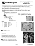
UM-OISPLUS-E003 Programmable Logic Controllers USER’S MANUAL Networking CONTENTS OIS PLUS Operator Interface Stations Toshiba International Corporation Page 1 Phone: 800.894.0412 - Fax: 888.723.4773 - Web: www.ctiautomation.net - Email: [email protected] Thank you for purchasing the OIS PLUS (Operator Interface Stations) product from Toshiba International Corp. OIS PLUS Series products are versatile industrial displays which are configured with Microsoft Windows based software. Manual’s Purpose and Scope This manual provides information on how to safely install, operate, and maintain your OIS PLUS. This manual includes a section of general safety instructions that describes the warning labels and symbols that are used throughout the manual. Read the manual completely before installing, operating, or performing maintenance on this equipment. This manual and the accompanying drawings should be considered a permanent part of the equipment and should be readily available for reference and review. Dimensions shown in the manual are in metric and/or the English equivalent. Toshiba International Corporation reserves the right, without prior notice, to update information, make product changes, or to discontinue any product or service identified in this publication. TOSHIBA is a registered trademark of the Toshiba Corporation. All other product or trade references appearing in this manual are registered trademarks of their respective owners. Toshiba International Corporation (TIC) shall not be liable for technical or editorial omissions or mistakes in this manual, nor shall it be liable for incidental or consequential damages resulting from the use of information contained in this manual. This manual is copyrighted. No part of this manual may be photocopied or reproduced in any form without the prior written consent of Toshiba International Corporation. Toshiba International Corporation. All rights reserved. Printed in the U.S.A. Page ii Phone: 800.894.0412 - Fax: 888.723.4773 - Web: www.ctiautomation.net - Email: [email protected] Important Notice The instructions contained in this manual are not intended to cover all details or variations in equipment types, nor may it provide for every possible contingency concerning the installation, operation, or maintenance of this equipment. Should additional information be required contact your Toshiba representative. The contents of this manual shall not become a part of or modify any prior or existing agreement, commitment, or relationship. The sales contract contains the entire obligation of Toshiba International Corporation. The warranty contained in the contract between the parties is the sole warranty of Toshiba International Corporation and any statements contained herein do not create new warranties or modify the existing warranty. Any electrical or mechanical modifications to this equipment without prior written consent of Toshiba International Corporation will void all warranties and may void the 3rd party (CE, UL, CSA, etc.) safety certifications. Unauthorized modifications may also result in a safety hazard or equipment damage. Contacting Toshiba’s Customer Support Center Toshiba’s Customer Support Center may be contacted to obtain help in resolving any system problems that you may experience or to provide application information. The center is open from 8 a.m. to 5 p.m. (CST), Monday through Friday. The Support Center’s toll free number is US 800-231-1412 Fax 713-466-8773 — Canada 800527-1204 — Mexico 01-800-527-1204. You may also contact Toshiba by writing to: Toshiba International Corporation 13131 West Little York Road Houston, Texas 77041-9990 Attn: PLC Marketing For further information on Toshiba’s products and services, please visit our website. Page iii Phone: 800.894.0412 - Fax: 888.723.4773 - Web: www.ctiautomation.net - Email: [email protected] Manual Revisions Please have the following information available when contacting Toshiba International Corp. about this manual. Name: Networking Manual Document: UM-OISPLUS-E003 Revision: Rev No. Date Description 0 2012/02/14 Initial Issue (for V200) 1 2012/03/20 Added I/O Mapping 2 2012/4/13 Added Engineering Corrections 3 2014/3/05 Added Additional Mapping Examples, Direct V200 Addressing, Trouble Shooting Related Manuals UM-OISPLUS-E001: Hardware & Specifications UM-OISPLUS-E002: Display Programming UM-OISPLUS-E004: Universal Serial (ASCII) Driver UM-V200-E001: Setup and Operation (for ladder logic programming) UM-V200-E002: Ladder Logic (how to use the ladder instructions) Page iv Phone: 800.894.0412 - Fax: 888.723.4773 - Web: www.ctiautomation.net - Email: [email protected] Table of Contents 0.1 Warning Labels Within Manual ............................................................................................................ 3 0.2 Equipment Warning Labels. ............................................................................................................. 5 0.3 Preparation....................................................................................................................................... 6 0.4 Installation Precautions .................................................................................................................... 7 0.5 Connection, Protection & Setup........................................................................................................ 9 0.6 System Integration Precautions ...................................................................................................... 11 0.7 3rd Party Safety Certifications. ........................................................................................................ 12 Serial Networking...................................................................................................................................... 13 1.1 Modbus RTU Master Setup ............................................................................................................ 15 1.1.1 Define the OIS45E PLUS Network .......................................................................................... 16 1.1.2 Enter OIS45E PLUS Tags ....................................................................................................... 17 1.1.3 Create the OIS45E PLUS Screens .......................................................................................... 18 1.2 Modbus RTU Slave Setup .............................................................................................................. 21 1.2.1 1.2.2 1.2.3 1.2.4 Define the V200 Network ........................................................................................................ 22 Enter V200 Tags ..................................................................................................................... 23 Program Ladder Logic in the V200 .......................................................................................... 27 Ladder Logic Programming with Modbus Tags........................................................................ 29 1.3 Direct Serial Addressing of V200 PLC Devices/Registers............................................................... 30 Ethernet Networking ................................................................................................................................. 32 2.1 Modbus TCP/IP Client Setup .......................................................................................................... 35 2.1.1 Define the OIS45E PLUS Network .......................................................................................... 36 2.1.2 Enter OIS45E PLUS Tags ....................................................................................................... 38 2.1.3 Create the OIS45E PLUS Screens .......................................................................................... 40 2.2 Modbus Server Setup ..................................................................................................................... 43 2.2.1 2.2.2 2.2.3 2.2.4 Define the V200 Network ........................................................................................................ 44 Enter V200 Tags ..................................................................................................................... 46 Program Ladder Logic in the V200 .......................................................................................... 50 Ladder Logic Programming with Modbus Tags........................................................................ 51 2.3 Direct Ethernet Addressing of V200 PLC Devices/Registers .......................................................... 52 Physical Connections ............................................................................................................................... 54 3.1 Modbus Serial Connections............................................................................................................ 55 3.2 Modbus Ethernet Connections ....................................................................................................... 58 Trouble Shooting ...................................................................................................................................... 59 4.1 Cables ............................................................................................................................................ 60 4.2 Communication Parameters ........................................................................................................... 60 4.3 Firmware Download ....................................................................................................................... 60 Page1 Phone: 800.894.0412 - Fax: 888.723.4773 - Web: www.ctiautomation.net - Email: [email protected] 0. General Safety Instructions and Information • Warning Labels Within Manual • Equipment Warning Labels • Preparation • Installation Precautions • Connection, Protection & Setup • System Integration Precautions • 3rd Party Safety Certifications Page2 Phone: 800.894.0412 - Fax: 888.723.4773 - Web: www.ctiautomation.net - Email: [email protected] 0.1 Warning Labels Within Manual DO NOT attempt to install, operate, maintain, or dispose of this equipment until you have read and understood all of the product warnings and user directions that are contained in this instruction manual. Listed below are the signal words that are used throughout this manual followed by their descriptions and associated symbols. When the words DANGER, WARNING, and CAUTION are used in the manual, they will be followed by important safety information that must be carefully adhered to. DANGER — The danger symbol is an exclamation mark enclosed in a triangle that precedes the word DANGER. The danger symbol is used to indicate an imminently hazardous situation that will result in serious injury, possible severe property and equipment damage, or death if the instructions are not followed. DANGER WARNING — The warning symbol is an exclamation mark enclosed in a triangle that precedes the word WARNING. The warning symbol is used to indicate a potentially hazardous situation that can result in serious injury, or possibly severe property and equipment damage, or death, if the instructions are not followed. WARNING CAUTION — The caution symbol is an exclamation mark enclosed in a triangle that precedes the word CAUTION. The caution symbol is used to indicate situations that can result in minor or moderate operator injury, or equipment damage if the instructions are not followed. CAUTION Page3 Phone: 800.894.0412 - Fax: 888.723.4773 - Web: www.ctiautomation.net - Email: [email protected] To identify special hazards, other symbols may appear in conjunction with the DANGER, WARNING, and CAUTION symbols. These warnings describe areas that require special care and/or strict adherence to the procedures to prevent serious injury and possible death. Electrical Hazard — The electrical hazard symbol is a lightning bolt enclosed in a triangle. The electrical hazard symbol is used to indicate high voltage locations and conditions that may cause serious injury or death if the proper precautions are not observed. Electrical Hazard Explosion Hazard — The explosion hazard symbol is an explosion image enclosed in a triangle. The explosion hazard symbol is used to indicate locations and conditions where molten exploding parts may cause serious injury or death if the proper precautions are not observed. Explosion Hazard Page4 Phone: 800.894.0412 - Fax: 888.723.4773 - Web: www.ctiautomation.net - Email: [email protected] 0.2 Equipment Warning Labels. DO NOT attempt to install, operate, maintain, or dispose of this equipment until you have read and understood all of the product warnings and user directions that are contained in this instruction manual. Shown below are examples of warning labels that may be found attached to the equipment. DO NOT remove or cover any of the labels. If the labels are damaged or if additional labels are required, contact your Toshiba representative for additional labels. The following are examples of the warning labels that may be found on the equipment and are there to provide useful information or to indicate an imminently hazardous situation that may result in serious injury, severe property and equipment damage, or death if the instructions are not followed. Examples of labels that may be found on the equipment. Page5 Phone: 800.894.0412 - Fax: 888.723.4773 - Web: www.ctiautomation.net - Email: [email protected] 0.3 Preparation Qualified Person A Qualified Person is one that has the skills and knowledge relating to the construction, installation, operation, and maintenance of the electrical equipment and has received safety training on the hazards involved (Refer to the latest edition of NFPA 70E for additional safety requirements). Qualified Personnel shall: • Have carefully read the entire operation manual. • Be trained and authorized to safely energize, de-energize, ground, lockout and tag circuits and equipment, and clear faults in accordance with established safety practices. • Be trained in the proper care and use of protective equipment such as safety shoes, rubber gloves, hard hats, safety glasses, face shields, flash clothing, etc., in accordance with established safety practices. • Be trained in rendering first aid. For further information on workplace safety visit www.osha.gov. Equipment Inspection • Upon receipt of the equipment inspect the packaging and equipment for shipping damage. • Carefully unpack the equipment and check for parts that were damaged from shipping, missing parts, or concealed damage. If any discrepancies are discovered, it should be noted with the carrier prior to accepting the shipment, if possible. File a claim with the carrier if necessary and immediately notify your Toshiba representative. • DO NOT install or energize equipment that has been damaged. Damaged equipment may fail during operation resulting in further equipment damage or personal injury. • Check to see that the model number specified on the nameplate conforms to the order specifications. • Modification of this equipment is dangerous and must not be performed except by factory trained representatives. When modifications are required contact your Toshiba representative. • Inspections may be required before and after moving installed equipment. • Keep the equipment in an upright position as indicated on the shipping carton. • Contact your Toshiba representative for assistance if required. Page6 Phone: 800.894.0412 - Fax: 888.723.4773 - Web: www.ctiautomation.net - Email: [email protected] • Handling and Storage • Use proper lifting techniques when moving the OIS; including properly sizing up the load, and getting assistance if required. • Store in a well-ventilated covered location and preferably in the original carton if the equipment will not be used upon receipt. • Store in a cool, clean, and dry location. Avoid storage locations with extreme temperatures, rapid temperature changes, high humidity, moisture, dust, corrosive gases, or metal particles. • Do not store the unit in places that are exposed to outside weather conditions (i.e., wind, rain, snow, etc.). • Store in an upright position as indicated on the shipping carton. • Include any other product-specific requirements. Disposal Never dispose of electrical components via incineration. Contact your state environmental agency for details on disposal of electrical components and packaging in your area. 0.4 Installation Precautions Location and Ambient Requirements • Adequate personnel working space and adequate illumination must be provided for adjustment, inspection, and maintenance of the equipment (refer to NEC Article 110-34). • Avoid installation in areas where vibration, heat, humidity, dust, fibers, steel particles, explosive/corrosive mists or gases, or sources of electrical noise are present. • The installation location shall not be exposed to direct sunlight. • Allow proper clearance spaces for installation. Do not obstruct the ventilation openings. Refer to the recommended minimum installation dimensions as shown on the enclosure outline drawings. • The ambient operating temperature shall be between 0° and 50° C (32° and 122° F). Mounting Requirements • Only Qualified Personnel should install this equipment. • Install the unit in a secure upright position in a well-ventilated area. • A noncombustible insulating floor or mat should be provided in the area immediately surrounding the electrical system at the place where maintenance operations are to be performed. • As a minimum, the installation of the equipment should conform to the NEC Article 110 Requirements For Electrical Installations, OSHA, as well as any other applicable national, regional, or industry codes and standards. • Installation practices should conform to the latest revision of NFPA 70E Electrical Safety Requirements for Employee Workplaces. Page7 Phone: 800.894.0412 - Fax: 888.723.4773 - Web: www.ctiautomation.net - Email: [email protected] Conductor Routing and Grounding • Use separate metal conduits for routing the input power, and control circuits. • A separate ground cable should be run inside the conduit with the input power, and control circuits. • DO NOT connect control terminal strip return marked CC to earth ground. • Always ground the unit to prevent electrical shock and to help reduce electrical noise. The Metal Of Conduit Is Not An Acceptable Ground. Page8 Phone: 800.894.0412 - Fax: 888.723.4773 - Web: www.ctiautomation.net - Email: [email protected] 0.5 Connection, Protection & Setup Personnel Protection • Installation, operation, and maintenance shall be performed by Qualified Personnel Only. • A thorough understanding of the OIS will be required before the installation, operation, or maintenance of the OIS. • Rotating machinery and live conductors can be hazardous and shall not come into contact with humans. Personnel should be protected from all rotating machinery and electrical hazards at all times. Depending on its program, the OIS can initiate the start and stop of rotating machinery. • Insulators, machine guards, and electrical safeguards may fail or be defeated by the purposeful or inadvertent actions of workers. Insulators, machine guards, and electrical safeguards are to be inspected (and tested where possible) at installation and periodically after installation for potential hazardous conditions. • Do not allow personnel near rotating machinery. Warning signs to this effect shall be posted at or near the machinery. • Do not allow personnel near electrical conductors. Human contact with electrical conductors can be fatal. Warning signs to this effect shall be posted at or near the hazard. • Personal protection equipment shall be provided and used to protect employees from any hazards inherent to system operation or maintenance. System Setup Requirements • When using the OIS as an integral part of a larger system, it is the responsibility of the OIS installer or maintenance personnel to ensure that there is a fail-safe in place (i.e., an arrangement designed to switch the system to a safe condition if there is a fault or failure). • System safety features should be employed and designed into the integrated system in a manner such that system operation, even in the event of system failure, will not cause harm or result in personnel injury or system damage (i.e., E-Off, Auto-Restart settings, System Interlocks, etc.). • The programming setup and system configuration of the OIS may allow it to start a motor unexpectedly. A familiarity with Auto-restart settings is a requirement to use this product. • Improperly designed or improperly installed system interlocks may render the motor unable to start or stop on command. Page9 Phone: 800.894.0412 - Fax: 888.723.4773 - Web: www.ctiautomation.net - Email: [email protected] The failure of external or ancillary components may cause intermittent system operation, i.e., the system may start a motor without warning or may not stop on command. • There may be thermal or physical properties, or ancillary devices integrated into the overall system that may allow the OIS to start a motor without warning. Signs at the equipment installation must be posted to this effect. • The operating controls and system status indicators should be clearly readable and positioned where the operator can see them without obstruction. • Additional warnings and notifications shall be posted at the equipment installation location as deemed required by Qualified Personnel. Page10 Phone: 800.894.0412 - Fax: 888.723.4773 - Web: www.ctiautomation.net - Email: [email protected] 0.6 System Integration Precautions The following precautions are provided as general guidelines for using an OIS in an industrial or process control system. • The Toshiba PLC is a general-purpose product. It is a system component and is used in conjunction with other items of industrial equipment such as PLCs, Loop Controllers, Adjustable Speed Drives, etc. • A detailed system analysis and job safety analysis should be performed by the systems designer or systems integrator before including the OIS in any new or existing system. Contact Toshiba for options availability and for application-specific system integration information if required. • The PLC may be used to control an adjustable speed drive connected to high voltage sources and rotating machinery that is inherently dangerous if not operated safely. Interlock all energy sources, hazardous locations, and guards in order to restrict the exposure of personnel to hazards. The adjustable speed drive may start the motor without warning. Signs at the equipment installation must be posted to this effect. A familiarity with Autorestart settings is a requirement when controlling adjustable speed drives. Failure of external or ancillary components may cause intermittent system operation, i.e., the system may start the motor without warning or may not stop on command. Improperly designed or improperly installed system interlocks and permissives may render a motor unable to start or stop on command • Control through serial communications can fail or can also override local controls, which can create an unsafe condition. System safety features should be employed and designed into the integrated system in a manner such that system operation, even in the event of system failure, will not cause harm or result in personnel injury or system damage. Use of the builtin system protective features and interlocks of the equipment being controlled is highly recommended (i.e., emergency-off, overload protection, etc.) • Never use the PLC units to perform emergency stops. Separate switches outside the OIS, the PLC, and the ASD should be used for emergency stops. • Changes or modifications to the PLC program should not be made without the approval of the system designer or systems integrator. Minor changes or modifications could cause the defeat of safety interlocks and permissives. Any changes or modifications should be noted and included with the system documentation. Page11 Phone: 800.894.0412 - Fax: 888.723.4773 - Web: www.ctiautomation.net - Email: [email protected] 0.7 3rd Party Safety Certifications. CE Marking The V200 Series Programmable Controllers conform to the directive and standards of ISO/IEC Guide 22 and EN 45014. UL Certification The UL Mark on a product means that UL has tested and evaluated representative samples of that product and determined that they meet UL requirements. The basic standards used to investigate this category are UL 508, the Standard of Safety for Industrial Control Equipment and UL Standard for Safety for Programmable Controllers. V200 Programmable Logic Controllers are certified NRAG &NRAG7 for use in hazardous locations RoHS Product Certification The V200 Series PLCs meet the European Directive on the Restriction of Hazardous Substances (RoHS) in electrical and electronic equipment companies This insures the chemical compliance of the V200. Page12 Phone: 800.894.0412 - Fax: 888.723.4773 - Web: www.ctiautomation.net - Email: [email protected] Serial Networking ♦ Modbus RTU Master ♦ Modbus RTU Slave Page13 Phone: 800.894.0412 - Fax: 888.723.4773 - Web: www.ctiautomation.net - Email: [email protected] It is possible to connect up to 32 devices together on a serial network as long as all devices have the same communications protocol. A common example would be several Toshiba ASD (adjustable speed drives/inverters) connected to an OIS PLUS display. In this case, all devices would communicate using Toshiba’s native ASD ASCII protocol. Often times it is necessary to connect several devices from different manufacturers. In this case the Modbus protocol is used since most manufacturers offer this as an option. An example of this is as shown below: OIS45E PLUS Modbus Master RS485 Modbus Serial Network Remote Display Modbus Slave V200 PLC bbbbbbbbbbbbbbbbbbbbbbbbbbbbbbbbbbbb Magnetic Flow Meter Modbus Slave Modbus Slave ASD Modbus Slave The following example will show how to setup a Modbus master and the Modbus slaves. For simplicity the example will only show setting up the V200 PLC as the Modbus slave. However, setting up the other slaves is very similar. The example will be a proof of communications example. There are two parts to the example. In part 1, the OIS45E PLUS will be setup to monitor special timing ON/OFF bits in the V200 PLC. Duty Cycle 0.4 Sec 0.8 Sec 1.0 Sec 2.0 Sec V200 Address M00482 M00483 M00484 M00485 OIS PLUS Modbus Address 035483 035484 035845 035846 The significance of the Modbus addresses will be explained when the slave is setup. In part 2 a simple loop-back test will be done. A number will be entered into D1 on the OIS45E PLUS. That number will be sent to the V200, moved from D0 (450001) to D1 (450002) in the V200, and read back in the OIS45E PLUS. Page14 Phone: 800.894.0412 - Fax: 888.723.4773 - Web: www.ctiautomation.net - Email: [email protected] When this example is setup and executing properly, it proves: ♦ Cabling is correct. ♦ Protocols are set correctly ♦ Communication parameters match ♦ Modbus register/device mapping is correct. ♦ Both devices are operating correctly. For a detailed understanding of serial networking, it is recommend that both Modbus master and slave examples be studied carefully before any setup/programming is started. 1.1 Modbus RTU Master Setup Open the OIL-DS software, click on New Project and select the OIS45E PLUS Page15 Phone: 800.894.0412 - Fax: 888.723.4773 - Web: www.ctiautomation.net - Email: [email protected] 1.1.1 Define the OIS45E PLUS Network Go to the navigation pane and define the network Alternate click here and click on Add Setup the Node 1 as shown: For Protocol select Modbus RTU (Unit as Master), accept all the defaults except baud rate, change to 19.2k. Click on Add Com1 on the OIS45E PLUS is now setup as the Modbus master. Page16 Phone: 800.894.0412 - Fax: 888.723.4773 - Web: www.ctiautomation.net - Email: [email protected] 1.1.2 Enter OIS45E PLUS Tags The next step is to assign Tags to the Modbus Master. In the Navigator Pane, click on Tags, the default tags assigned to the OIS45E PLUS are displayed automatically. Alternate click in the tags window and click on Add. Make sure Node name is Node 1 Modbus RTU (Unit as Master), then enter the Modbus coil 35483 as shown: Must be Node 1 Page17 Phone: 800.894.0412 - Fax: 888.723.4773 - Web: www.ctiautomation.net - Email: [email protected] Keep adding tags until all 6 of the tags shown below are added to Com1, Node 1: Note: Additional tags can be added at any time later on. 1.1.3 Create the OIS45E PLUS Screens Screens can now be created. In this example only one screen will be used. Create screen 1 as shown: Page18 Phone: 800.894.0412 - Fax: 888.723.4773 - Web: www.ctiautomation.net - Email: [email protected] Now the tags can be attached to the screen objects. Often times it is easier to attach the tags to the objects as the objects are created. It can be done either way. Select a button object. Assign properties using the properties pane. ON First select Feedback Tag. Then it is possible to select the ON image and the OFF image. OFF Select the input object. Pressing the data entry 99999 will cause the data entry keypad to appear. Key in a number and press enter Make sure screen name, Numeric Keypad, is selected.. Page19 Phone: 800.894.0412 - Fax: 888.723.4773 - Web: www.ctiautomation.net - Email: [email protected] Select the data display object Be sure to select the Modbus tag that is mapped to D0001 in the V200 PLC If desired, the beeper can be turned OFF for screen 1. Select the task under screen 1 and set it up as follows: This completes setup of the Modbus RTU master. Page20 Phone: 800.894.0412 - Fax: 888.723.4773 - Web: www.ctiautomation.net - Email: [email protected] 1.2 Modbus RTU Slave Setup Open the OIL-DS software if it is not already open, click on New Project and select the V200 PLC. Select the GPU288 model. Page21 Phone: 800.894.0412 - Fax: 888.723.4773 - Web: www.ctiautomation.net - Email: [email protected] 1.2.1 Define the V200 Network Go to the navigation pane and define the network. Alternate click here and click on Add For Protocol select Modbus RTU (Unit as Slave), accept all the defaults except Baud Rate. Select 19.2k then click on Add. Note: Communications settings must match settings in Modbus Master Page22 Phone: 800.894.0412 - Fax: 888.723.4773 - Web: www.ctiautomation.net - Email: [email protected] 1.2.2 Enter V200 Tags The next step is to assign Tags to the Modbus Slave. In the Navigator Pane, click on Tags, the default tags assigned to the V200 are displayed as shown. Alternate click in the tags window and click on Add. Look closely at the default tags above. Note that the special timing bits, M00480 – M00487 are default tags, nothing more has to done with them. But tags D0 and D1 must be created. Click Add. Then Add D1 in the same manner. Page23 Phone: 800.894.0412 - Fax: 888.723.4773 - Web: www.ctiautomation.net - Email: [email protected] When complete the tag list should look as follows: By this point a question should have arisen: How are the OIS45E PLUS and V200 registers mapped to Modus registers? The answer is: It happens automatically when a com port is assigned as a Modbus slave. For the V200 the mapping is as follows: Modbus Slave Mapping: OIS45E PLUS thru OIS120A & V200 PLCs. 1 Timer Register (R/W) T Tag Length 2 Bytes 2 Counter Register (R/W) C 2 Bytes 0000-0255 410001 - 410256 3 System Register (R/W) SW 2 Bytes 0000-0255 420001 - 420256 4 Retentive Register (R/W) R 2 Bytes 0000-1399 430001 - 431400 5 Input Register (R) XW 2 Bytes 0000-0399 440001 - 440400 6 Output Register (R/W) YW 2 Bytes 0000-0399 441001 - 441400 7 Internal Register (R/W) BW 2 Bytes 0000-0255 442001 - 442256 8 Index Registers I/J/K 2 Bytes 0000-0002 443001- 443003 9 Configuration Register MW 2 Bytes 0000-1599 460001-461600 10 Data Register (R/W) D 2 Bytes 0000-4095 450001 - 454096 11 Input Coil (R) X 1 Bit 0000-6399 000001 - 006400 12 Output Coil (R/W) Y 1 Bit 0000-6399 010001 - 016400 13 System Coil (R/W) S 1 Bit 0000-0099 020001 - 020100 14 Internal Coil (R/W) B 1 Bit 0000-4095 030001 - 034096 15 Timer Coil(R/W) T.xxxx 1 Bit 0000-0255 021001-021256 16 Counter Coil(R/W) C.xxxx 1 Bit 0000-0255 022001-022256 17 Configuration Coil(R/W) 00000-25599 035001- 060600 Sr.No. Register / Coil Abv. M 1 Bit Range Modbus Mapping 0000-0255 400001 - 400256 Notes: 1. Modbus register/coil tag length is the same as V200 register/coil tag length. 2. Each manufacturer has an equivalent table for their devices when they are designated a Modbus slave in a Modbus network. Without knowing the mapping between the slave devices internal registers/bits to the Modbus registers/bits, a Modbus network cannot be established. Page24 Phone: 800.894.0412 - Fax: 888.723.4773 - Web: www.ctiautomation.net - Email: [email protected] Modbus Slave Mapping: I/O Register Examples Example 1: GPU288 8in/8out GDI216 16in GDD288 8in/8out Inputs Outputs CPU Slot XW0000=440001 YW0000=441001 Slot 1 XW0100=440002 Slot 2 XW0200=440003 Example 2: GPU288 8in/8out GAD208 8 AI YW0200=441002 GDD288 8in/8out Inputs Outputs CPU Slot XW0000=440001 YW0000=441001 Slot 1 XW0100=440002 XW0101=440003 to XW0107=440009 Slot 2 Example 3: GPU288 8in/8out XW0200=440010 YW0200=441002 GAA242 4 AI/2 AO GDD288 8in/8out Inputs Outputs CPU Slot XW0000=440001 YW0000=441001 Slot 1 XW0100=440002 YW0100=441002 XW0101=440003 YW0101=441003 to XW0103=440005 Slot 2 XW0200=440006 YW0200=441004 Page25 Phone: 800.894.0412 - Fax: 888.723.4773 - Web: www.ctiautomation.net - Email: [email protected] Example 4: GPU288 8in/8out GDD288N*S 8in/8out GDD288N*S 8in/8out This example shows the assignment of I/O points to Modbus devices. CPU Slot Slot 1 Slot 2 Example 5: OIS PLUS Inputs Outputs X00000=0000001 Y00000=0100001 X00007=0000008 Y00007=0100008 X01000=0000017 Y01000=0100017 X01007=0000024 Y01007=0100024 X02000=0000032 Y02000=0100032 X02007=0000040 Y02007=0100040 TRPAIO0202L 2 AI/2 AO TRPOIO0808P 8 DI/8 DO Inputs Outputs XW0100=440001 YW0100=441001 XW0101=440002 YW0101=441002 XW0200=440003 YW0200=441003 OIS PLUS Slot 1 Slot 2 Notes: 1. If a program was written and then one module is changed to a different type, all of the Modbus addressing to the right of the changed module will change 2. Anytime a change is made to the networking be sure and download the firmware. Page26 Phone: 800.894.0412 - Fax: 888.723.4773 - Web: www.ctiautomation.net - Email: [email protected] 1.2.3 Program Ladder Logic in the V200 In order for the OIS45E PLUS data entered in D0 to loop back in D1, a MOV (move) instruction must be programmed in the V200. Open the ladder logic programming screen in the V200 PLC. Selecting Main Block 1 opens the programming pane. Create the following program. Go to Data Transfer and select the MOV instruction. Then add the END instruction Note: Programming outputs Y00002 thru Y00006 is not necessary. But it does allow confirmation of the special M timing bits in the V200 PLC. These are the same timing bits that control the bit buttons on the OIS45E PLUS. Page27 Phone: 800.894.0412 - Fax: 888.723.4773 - Web: www.ctiautomation.net - Email: [email protected] This completes setup of the V200 as a Modbus RTU slave. The programs created for the OIS45E PLUS and the V200 PLC can be loaded into each device respectively. Please see Section 3, Physical Connections for cabling information. When everything is complete, it will then be possible to observe Modbus network communication between the Modbus RTU master and the Modbus RTU slave. Again, it will confirm the following: ♦ Cabling is correct. ♦ Protocols are set correctly ♦ Communication parameters match ♦ Modbus register/device mapping is correct. ♦ Both devices are operating correctly. Page28 Phone: 800.894.0412 - Fax: 888.723.4773 - Web: www.ctiautomation.net - Email: [email protected] 1.2.4 Ladder Logic Programming with Modbus Tags At this time it is not possible to use Modbus registers/devices directly in the ladder program. For example, in the OIS45E PLUS if it is necessary to multiply the value in Modbus register 450002 (D1 in the V200 PLC) by 10, 450002 cannot be used in the ladder logic program. The following is not possible: 450002 Instead, the value in in 450002 must be copied into one of the OIS45E PLUS’s registers. This is done using a global task. Select Tasks from the navigation pane. Now D22 can be used as an operand in the multiplication function block above. If a lot of registers from the V200 PLC need to be used in the OIS45E PLUS ladder program, Block Copy is available. A bock of up to 999 continuous registers can be transferred with one Block Copy global task. Page29 Phone: 800.894.0412 - Fax: 888.723.4773 - Web: www.ctiautomation.net - Email: [email protected] 1.3 Direct Serial Addressing of V200 PLC Devices/Registers Section 1.1.2 described how to enter Modbus tags in the OIS45E PLUS so that it could read/write to devices/registers in the V200 PLC. This procedure is the same for any Modbus slave, not just the V200 PLC. It requires knowing how Modbus devices/registers are mapped to slave’s native device/registers. With Ver. 2.20 of the OIL-DS software the Modbus mapping is no longer necessary for the V200 PLC. The V200 PLC can be selected as a driver for the OIS45E PLUS. Select the V200 PLC Series Page30 Phone: 800.894.0412 - Fax: 888.723.4773 - Web: www.ctiautomation.net - Email: [email protected] Now, go to Add Tags. The V200 devices/registers and be directly selected. Continue adding tags until all of the desired V200 devices/registers are available in the OIS45E PLUS display. Using the procedure described above, the OIS45E PLUS can directly read/write to devices/registers in the V200 PLC. No Modbus mapping is necessary. Page31 Phone: 800.894.0412 - Fax: 888.723.4773 - Web: www.ctiautomation.net - Email: [email protected] Ethernet Networking ♦ Modbus TCP/IP Client ♦ Modbus TCP/IP Server Page32 Phone: 800.894.0412 - Fax: 888.723.4773 - Web: www.ctiautomation.net - Email: [email protected] Connecting industrial products together on an Ethernet network is becoming quite popular. Most manufactures offer the option of connecting their industrial products on a Modbus TCP/IP network. A typical network would be as shown: V200 PLC TCP/IP Sever G9 ASD TCP/IP Server G9 ASD TCP/IP Server Ethernet Switch OIS45E PLUS TCP/IP Client For the Ethernet Modbus TCP/IP network example, just one client and one server will be used. The objective is to show the setup and verify the communications. OIS45E PLUS TCP/IP Client V200 PLC TCP/IP Sever Ethernet The following Ethernet capable devices, using the OIL-DS software, can be setup as either a Modbus TCP/IP client or a Modbus TCP/IP server: OIS45E PLUS OIS70E PLUS V200, PU230 OIS120A V200 PU 200 Page33 Phone: 800.894.0412 - Fax: 888.723.4773 - Web: www.ctiautomation.net - Email: [email protected] The following example will show how to setup a Modbus client and a Modbus server. For simplicity the example will only show setting up the V200 PLC as the Modbus server. However, setting up the other servers is very similar. The example will be a proof of communications example. There are two parts to the example. In part 1, the OIS45E PLUS will be setup to monitor special timing ON/OFF bits in the V200 PLC. Duty Cycle 0.4 Sec 0.8 Sec 1.0 Sec 2.0 Sec V200 Address M00482 M00483 M00484 M00485 OIS PLUS Modbus Address 035483 035484 035845 035846 The significance of the Modbus addresses will be explained when the server is setup. In part 2 a simple loop-back test will be done. A number will be entered into D1 on the OIS40E PLUS. That number will be sent to the V200, moved from D0 (450001) to D1 (450002) in the V200, and read back in the OIS40E PLUS. When this example is setup and executing properly, it proves: ♦ Cabling is correct. ♦ Protocols are set correctly ♦ Communication parameters match ♦ Modbus register/device mapping is correct. ♦ Both devices are operating correctly. For a detailed understanding of Ethernet networking, it is recommend that both Modbus client and server examples be studied carefully before any setup/programming is started. Page34 Phone: 800.894.0412 - Fax: 888.723.4773 - Web: www.ctiautomation.net - Email: [email protected] 2.1 Modbus TCP/IP Client Setup Open the OIL-DS software, click on New Project and select the OIS45E PLUS Make sure the E (for Ethernet) model is selected. Page35 Phone: 800.894.0412 - Fax: 888.723.4773 - Web: www.ctiautomation.net - Email: [email protected] 2.1.1 Define the OIS45E PLUS Network Select Com 3 (Ethernet), alternate click here, and click on Add. Setup Node 1 as shown: This is the IP address of the server. Node 1 is the V200 CPU. Note that it’s Ethernet address IP address, 192.168.0 10, is setup here. If additional servers are mapped, each should be setup as a separate Node with its own Ethernet IP address. Page36 Phone: 800.894.0412 - Fax: 888.723.4773 - Web: www.ctiautomation.net - Email: [email protected] It is also necessary to assign an Ethernet IP address to the OIS45E PLUS. The OIS45E PLUS’s address is set in the project configuration window. Under the Project Menu, select Properties. Then click on the Ethernet tab. Set the IP Address as shown. Download port should be set at 5000. Accept the defaults for the Subnet Mask and the Default Gateway. Page37 Phone: 800.894.0412 - Fax: 888.723.4773 - Web: www.ctiautomation.net - Email: [email protected] 2.1.2 Enter OIS45E PLUS Tags The next step is to assign Tags to the Modbus Client. In the Navigator Pane, click on Tags, the default tags assigned to the OIS45E PLUS are displayed as shown. Alternate click in the tags window and click on Add. Make sure Node name is Node 1 Modbus RTU (Unit as Master), then enter the Modbus coil 35483 as shown: Add Tag Page38 Phone: 800.894.0412 - Fax: 888.723.4773 - Web: www.ctiautomation.net - Email: [email protected] Keep adding tags until all 6 of the tags shown below are added to Com1, Node 1: Note: Additional tags can be added at any time later on. Page39 Phone: 800.894.0412 - Fax: 888.723.4773 - Web: www.ctiautomation.net - Email: [email protected] 2.1.3 Create the OIS45E PLUS Screens Screens can now be created. In this example only one screen will be used. Create screen 1 as shown: Page40 Phone: 800.894.0412 - Fax: 888.723.4773 - Web: www.ctiautomation.net - Email: [email protected] Now the tags can be attached to the screen objects. Often times it is easier to attach the tags to the objects as the objects are created. It can be done either way. Select a button object. Assign properties using the properties pane. ON First select Feedback Tag. Then it is possible to select the ON image and the OFF image.. OFF Select the input object. Pressing the data entry 99999 will cause the data entry keypad to appear. Key in a number and press enter Make sure screen name “Numeric Keypad” is selected. This keypad will appear when the area 9999 is pressed. Page41 Phone: 800.894.0412 - Fax: 888.723.4773 - Web: www.ctiautomation.net - Email: [email protected] Select a data object to display. Be sure to select the Modbus tag that is mapped to D0001 in the V200 PLC If desired, the beeper can be turned OFF for screen 1. Select the task under screen 1 and set it up as follows: This completes setup of the Modbus TCP client. Page42 Phone: 800.894.0412 - Fax: 888.723.4773 - Web: www.ctiautomation.net - Email: [email protected] 2.2 Modbus Server Setup Open the OIL-DS software if it is not already open, click on New Project and select the V200 PLC. Select the GPU200 model. Page43 Phone: 800.894.0412 - Fax: 888.723.4773 - Web: www.ctiautomation.net - Email: [email protected] 2.2.1 Define the V200 Network Go to the navigation pane and define the network. Alternate click here and click on Add When the Node information screen appears, select Modbus TCP Server (Slave) for protocol. After this selection is made, no other choices are available in this setup box. Page44 Phone: 800.894.0412 - Fax: 888.723.4773 - Web: www.ctiautomation.net - Email: [email protected] Now it is necessary to assign an IP address for the V200. Under the Project menu, select Properties. Then click on the Ethernet tab. Set the V200’s IP address as shown: Leave everything else at the default settings. The V200 PLC is now setup as the Modbus TCP/IP server. If additional V200 PLCs are required as servers, they would be setup exactly as above except they would have a different IP address; 192 . 168 . 0 . 20 for example. Page45 Phone: 800.894.0412 - Fax: 888.723.4773 - Web: www.ctiautomation.net - Email: [email protected] 2.2.2 Enter V200 Tags The next step is to assign Tags to the Modbus Server. In the Navigator Pane, click on Tags, the default tags assigned to the V200 are displayed as shown. Click on Add. Note that special timing bits M00480 – M00487 are already defined as default tags. Nothing more has to be done with these tags. But D0 and D1 must be defined. Page46 Phone: 800.894.0412 - Fax: 888.723.4773 - Web: www.ctiautomation.net - Email: [email protected] When complete the tag list should look as follows: Note: Additional tags can be added at any time later on. By this point a question should have arisen: How are the OIS45E PLUS and V200 registers mapped to Modus registers? The answer is: It happens automatically when the Ethernet com port is assigned as a Modbus TCP/IP server. For the V200 the mapping is as follows: Modbus Server Mapping: OIS45E PLUS thru OIS120A & V200 PLCs. 1 Timer Register (R/W) T Tag Length 2 Bytes 2 Counter Register (R/W) C 2 Bytes 0000-0255 410001 - 410256 3 System Register (R/W) SW 2 Bytes 0000-0255 420001 - 420256 4 Retentive Register (R/W) R 2 Bytes 0000-1399 430001 - 431400 5 Input Register (R) XW 2 Bytes 0000-0399 440001 - 440400 6 Output Register (R/W) YW 2 Bytes 0000-0399 441001 - 441400 7 Internal Register (R/W) BW 2 Bytes 0000-0255 442001 - 442256 8 Index Registers I/J/K 2 Bytes 0000-0002 443001- 443003 9 Configuration Register MW 2 Bytes 0000-1599 460001-461600 10 Data Register (R/W) D 2 Bytes 0000-4095 450001 - 454096 11 Input Coil (R) X 1 Bit 0000-6399 000001 - 006400 12 Output Coil (R/W) Y 1 Bit 0000-6399 010001 - 016400 13 System Coil (R/W) S 1 Bit 0000-0099 020001 - 020100 14 Internal Coil (R/W) B 1 Bit 0000-4095 030001 - 034096 15 Timer Coil(R/W) T.xxxx 1 Bit 0000-0255 021001-021256 16 Counter Coil(R/W) C.xxxx 1 Bit 0000-0255 022001-022256 17 Configuration Coil(R/W) 00000-25599 035001- 060600 Sr.No. Register / Coil Abv. M 1 Bit Range Modbus Mapping 0000-0255 400001 - 400256 Notes: 1. Modbus register/coil tag length is the same as V200 register/coil tag length. 2. Each manufacturer has an equivalent table for their industrial devices when they are designated a Modbus server in a Modbus Ethernet network. Without knowing the mapping between the server devices internal registers/bits to the Modbus registers/bits, a Modbus network can not be established. Page47 Phone: 800.894.0412 - Fax: 888.723.4773 - Web: www.ctiautomation.net - Email: [email protected] Modbus Server Mapping: I/O Register Examples Example 1: GPU200 No I/O GDI216 16in GDD288 8in/8out Inputs Outputs CPU Slot Slot 1 XW0100=440002 Slot 2 XW0200=440003 Example 2: GPU200 No I/O GAD208 8 AI YW0200=441002 GDD288 8in/8out Inputs Outputs CPU Slot Slot 1 XW0100=440002 XW0101=440003 to XW0107=440009 Slot 2 Example 3: GPU200 No I/O XW0200=440010 GAA242 4 AI/2 AO YW0200=441002 GDD288 8in/8out Inputs Outputs XW0100=440002 YW0100=441002 XW0101=440003 YW0101=441003 CPU Slot Slot 1 to XW0103=440005 Slot 2 XW0200=440006 YW0200=441004 Page48 Phone: 800.894.0412 - Fax: 888.723.4773 - Web: www.ctiautomation.net - Email: [email protected] Example 4: GPU200 No I/O GDD288N*S 8in/8out GDD288N*S 8in/8out This example shows the assignment of I/O points to Modbus devices. Inputs Outputs X01000=0000017 Y01000=0100017 X01007=0000024 Y01007=0100024 X02000=0000032 Y02000=0100032 X02007=0000040 Y02007=0100040 CPU Slot Slot 1 Slot 2 Example 5: OIS PLUS TRPAIO0202L 2 AI/2 AO TRPOIO0808P 8 DI/8 DO Inputs Outputs XW0100=440001 YW0100=441001 XW0101=440002 YW0101=441002 XW0200=440003 YW0200=441003 OIS PLUS Slot 1 Slot 2 Notes: 1. If a program was written and then one module is changed to a different type, all of the Modbus addressing to the right of the changed module will change 2. Anytime a change is made to the networking be sure and download the firmware. Page49 Phone: 800.894.0412 - Fax: 888.723.4773 - Web: www.ctiautomation.net - Email: [email protected] 2.2.3 Program Ladder Logic in the V200 In order for the OIS45E PLUS data entered in D0 to loop back in D1, a MOV (move) instruction must be programmed in the V200. Open the ladder logic programming screen in the V200 PLC. Selecting Main Block 1 opens the programming pane. Create the following program. Go to Data Transfer and select the MOV instruction. Then add the END instruction This completes setup of the V200 as a Modbus RTU slave. The programs created for the OIS45E PLUS and the V200 PLC can be loaded into each device respectively. Please see Section 3, Physical Connections for cabling information. When everything is complete, it will then be possible to observe Modbus network communication between the Modbus client and the Modbus server. Again, it will confirm the following: ♦ Cabling is correct. ♦ Protocols are set correctly ♦ Communication parameters match ♦ Modbus register/device mapping is correct. ♦ Both devices are operating correctly. Page50 Phone: 800.894.0412 - Fax: 888.723.4773 - Web: www.ctiautomation.net - Email: [email protected] 2.2.4 Ladder Logic Programming with Modbus Tags At this time it is not possible to use Modbus registers/devices directly in the ladder program. For example, in the OIS45E PLUS if it is necessary to multiply the value in Modbus register 450002 (D1 in the V200 PLC) by 10, 450002 cannot be used in the ladder logic program. The following is not possible: 450002 Instead, the value in in 450002 must be copied into one of the OIS45E PLUS’s registers. This is done using a global task. Select Tasks from the navigation pane. Now D22 can be used as an operand in the multiplication function block above. If a lot of registers from the V200 PLC need to be used in the OIS45E PLUS ladder program, Block Copy is available. A bock of up to 999 continuous registers can be transferred with one Block Copy global task. Page51 Phone: 800.894.0412 - Fax: 888.723.4773 - Web: www.ctiautomation.net - Email: [email protected] 2.3 Direct Ethernet Addressing of V200 PLC Devices/Registers Section 2.2.2 described how to enter Modbus tags in the OIS45E PLUS so that it could read/write to devices/registers in the V200 PLC. This procedure is the same for any Modbus TCP/IP server, not just the V200 PLC. It requires knowing how Modbus devices/registers are mapped to server’s native device/registers. With Ver. 2.20 of the OIL-DS software the Modbus mapping is no longer necessary for the V200 PLC. The V200 PLC can be selected as a server for the OIS45E PLUS client. Finish setting up the Ethernet port Don’t forgot to add the Ethernet address and PLC port number Page52 Phone: 800.894.0412 - Fax: 888.723.4773 - Web: www.ctiautomation.net - Email: [email protected] Now, go to Add Tags. The V200 devices/registers and be directly selected. It is not necessary to use Modbus mapping. Continue adding tags until all of the desired V200 devices/registers are available in the OIS45E PLUS display. Using the procedure described above, the OIS45E PLUS can directly read/write the devices/registers in the V200 PLC. Page53 Phone: 800.894.0412 - Fax: 888.723.4773 - Web: www.ctiautomation.net - Email: [email protected] Physical Connections ♦ Modbus Serial Connections ♦ Modbus TCP/IP Ethernet Connections Page54 Phone: 800.894.0412 - Fax: 888.723.4773 - Web: www.ctiautomation.net - Email: [email protected] 3.1 Modbus Serial Connections There are 3 possible serial connections between the OIS45E PLUS and the V200 PLC. The connector on the OIS45E PLUS (and all the OIS PLUS displays) is the same, a 9 pin D-shell. However, the wires in the D-shell are connected differently for each type of connection. The three connections methods from the OIS45E PLUS are: Type RS232, 2 wire RS485, 4 wire RS485, 2 wire Port On V200 Com1 Com1 Com2 Cable RC-O-009H-00 RC-O-009I-00 RC-O-009J-00 RC-O-009H-00 Diagram V200 PLC OIS PLUS Only connect wires shown, do not connect any other wires. Page55 Phone: 800.894.0412 - Fax: 888.723.4773 - Web: www.ctiautomation.net - Email: [email protected] RC-O-009I-00 Diagram V200 PLC OIS PLUS Only connect wires shown, do not connect any other wires. RC-O-009J-00 Diagram OIS PLUS Page56 Phone: 800.894.0412 - Fax: 888.723.4773 - Web: www.ctiautomation.net - Email: [email protected] When connecting multiple V200 PLCs together using their Com1 ports, an RJ45 to screw terminal adapter is often quite useful. The above device, part number NV-RJ45A, is from: Network Video Technologies 4005 Bohannon Drive • Menlo Park, CA 94025 • USA (+1) 650.462.8100 • 800.959.9870 • FAX (+1) 650.326.1940 Page57 Phone: 800.894.0412 - Fax: 888.723.4773 - Web: www.ctiautomation.net - Email: [email protected] 3.2 Modbus Ethernet Connections There are two types of Ethernet cables used: Cross cable Straight thru cable. A cross cable is used for a direct connection between a computer and the Ethernet port on an OIS PLUS or V200 PLC. It is also used when the Ethernet port on the OIS PLUS is connected directly to the Ethernet port on the V200 PLC. A straight thru cable is used for connecting the OIS PLUS or V200’s Ethernet port to an Ethernet switch. Be sure to use the correct cable depending on the connection. Note: The OIS PLUS and V200 PLCs support automatic crossover detection. This allows these devices to configure their Ethernet port for correct operation according to the cable connected. So even if the correct cable is not selected, the connection may still work. Page58 Phone: 800.894.0412 - Fax: 888.723.4773 - Web: www.ctiautomation.net - Email: [email protected] Trouble Shooting Page59 Phone: 800.894.0412 - Fax: 888.723.4773 - Web: www.ctiautomation.net - Email: [email protected] 4.1 Cables Recheck that the cables as described in Section 3 (previous section) are correct. If the cables are not connected correctly, communication between equipment in the network will not be established. The red LED will be blinking. 4.2 Communication Parameters 1. Serial: Recheck that the baud rate, parity, number of bits, and number of stop bits are the same in all connected equipment. See if connection is possible with a Modbus Master/Slave simulator like ModScan32/ModSim32 2, Ethernet: Make sure that only the last portion of the Ethernet I/P address is different in each piece of connected equipment. Try to ping the Ethernet port using the command prompt ping command. When enter is pressed the command prompt will attempt to send 4 packets to the specified address. If the packets come back there is no Ethernet address problem. If the 4 packets are lost the Ethernet address is incorrect or missing. 4.3 Firmware Download Whenever a network is configured, a firmware download is necessary. If in doubt, download the firmware again into each piece of connected equipment. Page60 Phone: 800.894.0412 - Fax: 888.723.4773 - Web: www.ctiautomation.net - Email: [email protected]