1
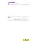
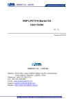
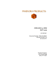
User Manual LPC1100-StickView V1.0 for LPC1100-Stick Contents 1 What is the LPC1100-Stick? 2 2 System Components 2 3 Installation 3 4 Updates 4 5 Starting the LPC-StickView Software 5 6 Operating the LPC1100-Stick 7 6.1 Start Page Buttons 6.2 Menu Commands 7 14 7 EEMBC CoreMark® Application 16 8 EEMBC PowerBench® Application 17 9 Troubleshooting 18 Rev. 03/2010 – 001 Windows®, Windows XP®, Windows Vista® and Windows7® are registered trademarks of the Microsoft corp. LPC is a registered trademark of NXP. All trademarks of other companies used in this document refer exclusively to the products of these companies. LPC1100-StickView User Interface 1 2 What is the LPC1100-Stick? The LPC1100-Stick is an easy to use development system designed to demonstrate the ARM/Cortex-core-based microcontroller features and peripheral usage. The LPC1100-Stick features are implemented in a USB stick and controlled by an ARM/Cortex-core-based microcontroller from NXP. When connecting the LPC1100-Stick to a PC's USB port, the microcontroller begins to run the default application which can be controlled with the LPC1100-StickView user interface. 2 System Components The following components are provided: • LPC1100-Stick hardware • CD ROM including HiTOP54 IDE and debugger, GNU C Compiler, Tasking Compiler (evaluation version), LPC1100-Stick USB drivers • Full Tasking compiler license bound to the stick (can be obtained by registration). • LPC1100-StickView user interface, user documentation (electronic version) and other documents and examples. • EEMBC PowerBench® application including NI runtime environment. LPC1100-StickView User Interface 3 3 Installation Before plugging in the LPC1100-Stick, insert the supplied autorun CD in your CD-ROM drive and follow the instructions on the screen to install the software. The setup process performs the installation of the LPC1100-StickView software and a pre-installation of the drivers required for the USB device. In addition, the tool chain with debugger and compiler is installed. After successful installation, the LPC1100-Stick can be plugged into one of your PC's USB ports. The pre-installed drivers will be selected automatically and the LPC-Stick comes up as a new device called LPC1100-Stick. On most Windows operating systems, the drivers for the device are found and installed automatically. If the stick is plugged into the PC for the first time, the installed driver is assigned to the stick. When the stick is powered by the USB port, the microcontroller begins to run the default application which can be controlled by the LPC1100-StickView user interface. Manual Driver Installation The LPC1100-Stick does not need any external drivers to be installed. The Microsoft generic drivers are used. Deinstallation For deinstallation of the LPC1100-StickView software, select the Uninstall item from the LPC1100-Stick program menu. LPC1100-StickView User Interface 4 4 Updates The LPC1100-Stick demo application is under continuous development. Furthermore, the supported functionality of a specific LPC1100-Stick depends on the firmware stored in the flash memory of the stick device. To be able using the newest features, it is recommended to visit the LPC-Stick WEB page from time to time. Updates, FAQs and other information are provided there. Note To get the current source code installed, the HiTOP environment must be installed before the update is executed. LPC1100-StickView User Interface 5 Starting the LPC-StickView Software When starting LPC1100-StickView by double-clicking the following desktop icon: the following window (or similar) is presented after the device is found: The current state is displayed in the bottom status bar of the LPC1100StickView window. Normal state is "Connected to LPC11xx-Stick SerNo: nnnnn". The main window provides buttons for the implemented function and their controls. Tabs or menu entries which are currently not activated (either while an extension board is not connected or while a license file is missing or while the feature is not implemented in the current version) are greyed out and can not be selected. For an overview of the buttons, refer to p. 10. For an overview of the menu commands, see p. 14. 5 LPC1100-StickView User Interface Notes Reprogramming the Flash Memory With delivery, the demo application supporting the LPC1100-StickView software features is located in the Flash memory. If you modify it by using HiTOP with another application, you will first have to reprogram with the demo application as follows: 1 Start the LPC1100-StickView software if not running. 2 Execute the Application > Update command. Using HiTOP to reprogram the LPC1100 Stick device: 1 Exit the LPC1100-StickView software if started. 2 Start HiTOP54 for LPC1100-Stick. 3 In the following folder, open the project file "Demo.htp" using the Project > Open command: ..\Hitex\HITOP54-LPC1100-Stick\Examples\GNU\Demo\Demo.htp This will reprogram the Flash memory. 4 Reset the target with HiTOP's Debug > Reset command, restart the application executing HiTOP's Go command and close HiTOP. 5 Restart the LPC1100-StickView software. Debugging the Demo Application Example with HiTOP When debugging the demo application example with HiTOP, you will have to note the following: Start the LPCStickView software and keep it running while debugging the demo application in HiTOP. 6 LPC1100-StickView User Interface 6 Operating the LPC1100-Stick From the start page the main windows tab view is entered. Within the main window tab, different control features for the specific microcontroller and the peripherals can be selected and demonstrated. 6.1 Start Page Buttons Measure Changes into page view and opens the Measurement page. Coremark Run the CoreMark benchmark test and show the results. Setup and start power conditions for the LPC1100 controller. EEMBC Analysis Run the PowerBench® benchmark test and analyze the results. Setup and start power conditions for the LPC1100 controller. Power Features Record and show the flow of the current while active and sleep phase (LPC1100 in Power Down Mode) of the application. Setup and start power conditions for the LPC1100 controller. 7 LPC1100-StickView User Interface 8 Measure Two different measurements are displayed. 1. AD Converter: The LPC1100-ADC0 connected to the green LED measure (used as ambient light sensor) and the ADC1 pin of the stick (PIO1.0) is scanned as the second channel. Caused by the floating pin on channel 2, the ADC is floating impacted by channel 1. 2. Core Supply/Current: The current consumption is measured by the stick hardware. LED Controls: LED1: The LED1 checkbox provides a simple IO command to light up the red LED on the stick. LED2: The LED2 checkbox enables the green LED on the stick and changes the ADC1 input to a digital output and vice versa. LPC1100-StickView User Interface 9 CoreMark The CoreMark page enables the user to run the CoreMark benchmark with the most relevant setting of CPU clock speed, CPU supply voltage and number of iteration of the CoreMark benchmark. All results generated by the CoreMark application are displayed in the CoreMark results box. Changes the CPU supply voltage. The changes are applied by the LPC1100 controller before executing the CoreMark benchmark. Changes the CPU core frequency to typical values. The changes are applied by the LPC1100 controller before executing the CoreMark benchmark. Changes the number of iterations for the CoreMark benchmark. Clicking on this button will initiate the LPC1100 controller to apply the new PLL, supply and iterations settings and start the CoreMark benchmark application on the target CPU. LPC1100-StickView User Interface 10 EEMBC Analysis The EEMBC Analysis page enables the user to specify the most relevant settings of CPU clock speed and CPU supply voltage. Both parameters have essential impact on the current consumption. PLL state and current power consumption is displayed in the boxes on top of the dialog window. Changes the CPU supply voltage. The changes are applied with the Apply button. Changes the CPU core frequency to typical values. The changes are applied with the Apply button. After clicking on this button the LPC1100 controller will apply the new frequency and supply voltage settings. LPC1100-StickView User Interface 11 Clicking on this button will initiate the LPC1100 controller to start the benchmark application on the target CPU. The power consumption and the supply voltage are recorded to a file. The Progress Bar show the status of the benchmark application. Note: Depending of the PLL settings it can take up to 1min until the measured data (voltage and current) are transferred from the LPC1100-Stick to the LPC1100-StickView. The data sampling can be interrupted by the user. The end of the sampling phase will be confirmed by a popup message. Clicking on this button will start the external PowerBench® application from EEMBC to analyze the sampled data from above. LPC1100-StickView User Interface 12 Power Features The Power Features page enables the user to see the power flow of the LPC1100 controller when it is active and in the Power Down Mode. During the active period the LPC1100 controller executes the CoreMark benchmark. Changes the CPU supply voltage. The changes are applied by the LPC1100 controller after clicking the Start button. Changes the CPU core frequency to typical values. The changes are applied by the LPC1100 controller after clicking the Start button. Changes the number of iterations for the CoreMark benchmark. The changes are applied by the LPC1100 controller after clicking the Start button. LPC1100-StickView User Interface 13 This slider sets the time (in seconds) which the LPC1100 controller spends in a Power Down Mode after executing the CoreMark benchmark . The changes are applied by the LPC1100 controller after clicking the Start button. The following Power Down Modes can be selected: • Sleep Mode • Deep-Sleep Mode • Deep-Power-Down Mode Clicking on this button will initiate the LPC1100 controller to start the CoreMark benchmark application on the target CPU. The power consumption is recorded to a buffer and then displayed in the power flow graph. The Progress Bar show the status of the benchmark application. Note: Depending on the PLL settings it can take up to 1min until the measured data are transferred from the LPC1100Stick to the LPC1100-StickView. Using this button, the data sampling can be interrupted. Clicking on this button will wake up the LPC1100 controller from the current Power Down Mode. LPC1100-StickView User Interface 6.2 14 Menu Commands LPC-Stick Hardware Reset Executing this command, the LPC1100-StickView applies a resets to the LPC1100-Stick device setting it into its initial state via the reset pin. SoftReset Device Executing this command, the LPC1100-StickView applies software reset of the LPC1100-Stick application to its initial state. Show Start Page Executing this command, the initial start page of the LPC1100-StickView is displayed. Exit Exiting the LPC1100-StickView software. Application Update Updating the firmware. Help Info… Displays the current version of the GUI and the firmware. LPC-Stick on the Web Link to external web page for the LPC-Stick variants. User Manual LPC1100-Stick LPC1100-StickView user manual (this document). Data Sheet LPC1100-Stick LPC1100-Stick data sheet (Technical Data, Connections and Controls, Pin Assignment etc.). Schematic LPC1100-Stick LPC1100-Stick schematics. Data Sheet LPCPrototype-Board LPC-Prototype-Board data sheet (Technical Data, Connections and Controls, Pin Assignment etc.). Schematic LPCPrototype-Board LPC-Prototype-Board schematics. LPC1100-StickView User Interface 15 Help EEMBC.org Link to EEMBC on the web. EEMBC Software Overview of the software provided by EEMBC. EEMBC CoreMark Overview of the CoreMark® application provided by EEMBC. EEMBC EnergyBench Overview of the EnergyBench® software provided by EEMBC. LPC1100-StickView User Interface 7 16 EEMBC CoreMark® Application The CoreMark® benchmark application is an integrated part of the Demo software delivered with the stick. In the Demo examples directory, the sources can be found as they are delivered in the original version. The hardwarespecific adaptation to the stick is made in the files ..\Examples\GNU\Demo\coremark_v1.0\LPC1114\core_portme.c and ..\Examples\GNU\Demo\coremark_v1.0\LPC1114\core_portme.h. The files provide a configuration including the number of iterations and interfaces to device-specific features like timer handler. The CoreMark® application can be run separately if the demo project is loaded with the HiTOP debugger environment. To run the specific task, start HiTOP for LPC1100-Stick and load the project from the demo examples directory: ..\Examples\GNU\Demo\project\Demo.htp After loading the application, invoke the CoreMark® test by clicking on the button in HiTOP's Execute Script toolbar. The application is set to start the CoreMark® part. It takes about 65 seconds for a complete run. After the CoreMark® test has finished, the controller is stopped and an output is generated in the following file: ..\Examples\GNU\Demo\doc\Results_LPC11xx.html The file contains a collection of the most significant data from the CoreMark® test run. LPC1100-StickView User Interface 8 17 EEMBC PowerBench® Application EEMBC provides software to generate and analyze the data acquired by a sufficient measurement tool in respect of power consumption and energy facing data. The measurement tool is an integrated part of the stick hardware in conjunction with the LPC1100-StickView user interface. The data are collected with standard controller precision and fed into the LPC1100-StickView GUI application. The GUI provides a mechanism to save the data as text files for individual usage and comparison. The GUI also includes a button (Analyze Data) to call the PowerBench® application with a selected file. The PowerBench® application can be started manually if required: • Start the file analyze1.exe in the ..\HiTOP54-LPC1100-Stick\LPC-StickViewView\EEMBC\ folder and enter the data for iterations and an input file path and name as minimum information. • Click on the Read button and check the results. The PowerBench® application requires the National Instruments LabVIEW Run-Time Engine 8.5 or higher. The Run-Time Engine is installed with the LPC1100-StickView package. For more information on EEMBC, use the LPC1100-StickView's Help menu. LPC1100-StickView User Interface 9 18 Troubleshooting Driver Installation Possible Reason Installation process is not coming up The CD autostart feature is disabled. No driver found after plugging in the LPC1100-Stick device The installation process was not done. The Windows dialog to confirm the driver installation was rejected by the user. Remedy • • • • Start the installation process by executing the setup.exe file from the CD ROM drive. Start the installation process by executing the setup.exe file from the CD ROM drive. If the installation was done successfully, the operating system asks for the according driver after plugging in the LPC1100-Stick device. When prompted by the operating system, confirm to install the drivers automatically. If the installation fails or was not done before, replug the Stick device and find an appropriate USB connector to try again Software Messages Possible Reason Can not open port … to communicate with the device The LPC1100-Stick device is not connected to the USB port of the PC or the LPC1100-StickView software was not able to detect the LPC1100-Stick on the selected port. Remedy • • • Check if the device is connected to a functional USB port of the PC. Check if other devices on a USB port prevent the communication to the device. Check if the driver is installed, or reinstall the driver from the CD. or The driver was not installed properly LabVIEW RunTime Engin required The EEMBC PowerBench® application needs the LabVIEW® Ruin-Time Engine • Reinstall the LPC1100-StickView application with all components.