1
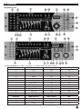
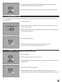
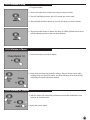
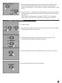
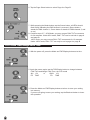
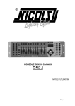
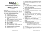
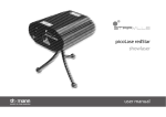
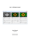
Owner‘s Manual
DMX MASTER I & II
Content
Introduction........................................................................................................................................................................2
Technical Specification . ......................................................................................................................................................2
Maintenance and care........................................................................................................................................................2
1. Notes on safety...............................................................................................................................................................3
2. General Instructions........................................................................................................................................................3
3. Overview.........................................................................................................................................................................5
4. Operation Guide.............................................................................................................................................................7
4-3 Programming Chase...................................................................................................................................................13
4-4 Assign/Reverse DMX channel.....................................................................................................................................16
4-5 Running Scenes..........................................................................................................................................................22
4-6 Running Chases..........................................................................................................................................................23
4-7 MIDI Operation..........................................................................................................................................................25
4-8 Send File Dump..........................................................................................................................................................26
4-9 Receive File Dump.......................................................................................................................................................26
5. Disposal........................................................................................................................................................................27
Introduction
Thank you for purchasing our DMX MASTER I or II. Enjoy your new equipment and make sure to read this
manual carefully before operation!
Technical Specification
Power Input ...............................................................
DMX Input .................................................................
DMX Output . .............................................................
MIDI Signal ................................................................
Audio Input ................................................................
Dimensions . ..............................................................
Weight (approx.) ........................................................
DC 9V, 300 mA min.
3 pin male XLR
3 pin female XLR
5 pin standard interface
By built-in microphone or line in
482x132x73 mm
2.5 kg
Our products are subject to a process of continual further development. Therefore modifications to the
technical features remain subject to change without further notice.
Maintenance and care
• Never submerse the device in water or any other liquid. Don‘t let any liquid get into the housing. This would
damage the unit and cause a short circuit.
• Before cleaning the device you must disconnect it from the mains. Clean the surface of the device only with
a slightly damp cloth. Never use petrol, solvents or any aggressive cleaners! These could damage the surface of the unit‘s housing!
2
1. Notes on safety
For your own safety you should read through this chapter at first completely!
•
•
•
•
•
•
•
•
•
•
•
•
•
•
Risk of electrical shocks!
Only connect the device using the mains adaptor supplied to a properly wired and earthed mains power
socket providing mains voltage of 230 V ~ /50 Hz.
Do not operate the device if the power adaptor, its cord or the mains plug is damaged.
Never submerse the device in water. Wipe it with a slightly moistened cloth only.
Do not expose the device to rain and never use it in a damp or wet environment.
Make sure that the power adaptor or the adaptor cable never becomes wet or moist during use.
Under no circumstances may you open the housing of the device or the adaptor. Should you do so your
safety would not be assured and the warranty will become void. There are no operational components whatsoever inside, only really high voltage that can give you a deadly shock!
Do not place objects containing fluids, e.g. flower vases or beer bottles, on or near the device.
Notice regarding disconnection from mains-power:
To completely disconnect the device from mains power, you must disconnect the adaptor from the power
socket. For this reason the device should be placed in a position where unobstructed access to the power
socket is assured at all times, so that in an emergency you will be able to immediately pull out the adaptor.
To eliminate the risk of fire you should completely disconnect the adaptor from the power socket when the
device is not going to be used for a long time, for example, during holidays.
Always grasp the power adaptor itself. Do not pull on the cord and never touch the power adaptor with wet
hands as this could result in a short circuit or an electrical shock. Do not place the device, speakers or anything else on the adaptor cord and make sure that it does not become clamped. Never tie knots in the adaptor cord and do not bind it together with other cables. Lay the adaptor cord so that no one can step on or
stumble over it. A damaged power adaptor can cause a fire or an electrical shock. Check the power adaptor
and its cord from time to time. Should it become damaged contact our customer service department to have
it replaced.
Risk of fire!
Never leave the device unattended during operation.
Never cover the ventilation slots of the device while it is on. Do not place the device in locations that are
subject to direct sunlight. If you do, it may overheat and become irreparably damaged.
Never operate the LED commander in the vicinity of heat sources such as cookers, heating elements or
other heat producing installations.
Do not place open fire sources, such as candles, on the device.
Before a storm and/or a thunderstorm with a risk of lightning, please disconnect the device from the electrical power source.
Risk of personal injury!
• Keep children away from the power adaptor and the device. Children frequently underestimate the dangers
of electrical devices.
• Provide a stable location for the device.
• Do not operate the device if it has sustained a fall or is damaged. Have the device checked or, if necessary,
repaired by qualified technicians.
2. General Instructions
Please read the user manual carefully, as it includes important information regarding details of operation,
maintenance, and technical data. Keep this manual with the unit for future consult.
Features
XX 192 DMX channels.
XX 12 scanners of 16 DMX channels.
XX 30 banks of 8 programmable scenes.
XX 6 chases of 240 programmed scenes from 30 banks
3
XX 8 faders for manual control
XX All data can be sent or received between two units
XX Auto programs (scenes and chases) under control by Wait Time sliders (or Tap Sync) and Fade Time
sliders
XX Fade Time/Assign Fade Time
XX The scanners under control by Pan and Tilt jog wheels (Master II)
XX Fine adjustment of the Pan and Tilt
XX Reverse DMX channels causing the faders to control the output reversely
XX Preview assigned or reversed DMX channels
XX 8 CH./16 CH. mode for Assigned or Reversed DMX channels
XX Blackout master / Stand alone mode
XX Manual override
XX Built-in microphone for Music triggering
XX MIDI control over banks, chases and Blackout
XX LCD display
XX DMX polarity select
XX Power failure memory
XX Auto Address
WARNINGS
• DO NOT let any inflammable liquids, water or metal objects enter the unit.
• Should any liquid be spilled on the unit, DISCONNECT the power supply to the unit immediately.
• STOP using the unit immediately In the event of serious operation problems and either contact your local
dealer for a check or contact us directly.
• DO NOT open the unit - there are no user serviceable parts inside.
• NEVER try to repair the unit yourself. Repairs by unqualified people could cause damage or faulty operation. Contact your nearest dealer.
CAUTIONS
• This unit is NOT intended for home use.
• After having removed the packaging check that the unit is NOT damaged in any way. If in doubt, DON‘T use
it and contact an authorized dealer.
• Packaging material (plastic bags, polystyrene foam, nails, etc.) MUST NOT be left within children‘s reach, as
it can be dangerous.
• This unit must only be operated by adults. DO NOT allow children to tamper or play with it.
• NEVER use the unit under the following conditions:
In places subject to excessive humidity.
In places subject to vibrations or bumps.
In places with a temperature of over 45 °C/113 °F or less than 2 °C/35.6 °F.
• Protect the unit from excessive dryness or humidity (ideal conditions are between 35% and 80%).
• DO NOT dismantle or modify the unit.
4
3. Overview
Controller Front
1)Scanner Buttons (1-12): 12 scanners of 16 DMX channels & fader control
Scanners
1
DMX channels
1-16
Fader control
Off
LED
Off
2
3
4
5
6
7
8
9
10
11
12
17-32
33-48
49-64
65-80
81-96
97-112
113-128
129-144
145-160
161-176
177-192
Off
Off
Off
Off
Off
Off
Off
Off
Off
Off
Off
Off
Off
Off
Off
Off
Off
Off
Off
Off
Off
Off
Scanners
1
DMX channels
1-16
Fader control
On
LED
On
2
3
17-32
33-48
On
On
On
On
5
Scanners
4
5
6
7
8
9
10
11
12
DMX channels
49-64
65-80
81-96
97-112
113-128
129-144
145-160
161-176
177-192
Fader control
On
On
On
On
On
On
On
On
On
LED
On
On
On
On
On
On
On
On
On
Press a scanner button to turn on manual fader control. Press the scanner button again to turn off fader
control. The LED next to the button lights up or goes out to indicate your selection.
2. Scene Buttons
Press the scene buttons to load or store your scenes. There are a maximum of 240 programmable scenes.
3. Faders
These faders are used to control the intensity of channel 1-8 or channel
9-16 depending upon the selected page.
4. Page Select Button
Used to select page between Page A (1-8) and Page B (9-16).
5. Fog Machine Button
Activates Fog Machine .
6. WAIT Time Slider
Used to adjust the chase wait time within the range of 0.1 second to 5
minutes.
7. Fade Time Slider
Used to adjust the fade time. Fade time is the amount of time it takes for a
scanner(or scanner) to move from one position to another, for the dimmer
to fade in or fade out.
8. LCD Display
Shows the current activity or programming state.
9. Pan Wheel
This jog wheel is used to control the pan of the scanner or for programming.
10. Tilt Wheel
This jog wheel is used to control the Tilt of the scanner or for programming.
11. Program Button
Activates Program mode.
12. MIDI/Rec
Used to control MIDI operation or to record programs.
13. Auto/Del
Activates Auto mode or to delete scenes or chases.
14. Music/Bank Copy
Activates Music mode or to copy a bank of scenes
15. Bank Up/Down
Press the Up/Down button to select from 30 banks.
16. Tap/Display
Used to create a standard beat or to change the value mode between %
and 0-255.
17. Blackout/Stand alone Button
Tap to momentarily pause the whole output. Hold on this button to enter
Stand alone mode.
18. Chase Buttons(1-6)
These buttons are used for activating the chase of programmed scenes.
19. Fine Button
When Fine is on, the Pan or Tilt wheel will control the scanner in the smallest increment.
20. Mode Button
Pressing Fine and Mode buttons allows to activate Assign or Reverse
mode.
6
Rear View
1. AUDIO IN
0.1V~1Vp-p.
2. MIDI IN
Receives MIDI data.
3. DMX Polarity Select
Used to select DMX polarity.
4. DMX Out
This connector sends your DMX value to the DMX scanner or DMX pack.
5. DMX In
This connector accepts your DMX input signals.
6. Fog Machine Connector
This connector is used to plug in the Fog Machine.
7. DC Input
DC 9 -12V, 300mA min.
8. Power Switch
This switch turns On/Off the power.
Fog machine diagram
4. Operation Guide
General
This unit allows you to program 12 scanners of 16 DMX channels, 30 banks of 8 programmable scenes, 6
chases of 240 programmed scenes using 8 faders and other function buttons. With the use of two jog wheels,
you may easily control the Pan or Tilt of the scanners. To tailor your special effect lighting, this unit enables
you to Assign or Reverse the DMX channels. In addition, two units can set up communication so that they can
send or receive file dump.
Display Information
The LCD Display contains a maximum of 2x8 characters.
LCD Display Message
CHASE 5
Chase 5 is activated.
STEP 002
The 2nd step of a chase
7
DATA 151
DMX value (000-255)
WT: 1M36S
The current Wait Time is 1 minute and 36 seconds
TP: 5.32S
The time of the last two taps is 5.32 seconds
FT: 10.5S
Fade Time is 10.5 seconds
ASS 07 08
Assign DMX channels 7 and 8
RES 10 13
Reverse DMX Channels 10 and 13
SN 6
Scene 6
BK 03
Bank 03
4-1 Program Enable
When the power is turned on, this unit enters Manual mode automatically. Press the Program button for three
seconds to activate Program mode, the LED near to this button lights indicating Program in active.
4-2 Programming Scenes
1. Enter Program mode.
2. Press the Scanner button to turn on its fader control, which is indicated by
the lit LED.
You may select several scanners at a time by tapping of these Scanner
buttons, so you can set several scanners at a time.
3. Move the faders to select your desired dimmer intensity if you are using
a dimmer. You can also use the two jog wheels to control the Pan or Tilt
movement of the scanner.
4. If necessary , you may tap the Page Select button to control the second set of 8 DMX channels.
5. Once the scene is satisfactory, tap the MIDI/Rec button to program this
scene into memory.
6. Tap the Bank Up/Down button to select the bank you want to store your
scene into. There are total 30 banks you can select, you may store up to 8
scenes into each bank.
7. Tap the Scene button to store your scene, all LEDs and the Segment
Display will flash three times briefly indicating this operation, then the LCD
will show the bank and the scene.
8
8. Repeat steps 3-7 until all desired scenes have been programmed into
memory. Tap the Scanner button again to turn off its fader control. To
set another scanner (scanner), you may tap the corresponding Scanner
button to turn on its fader control, then you may begin your programming
again.
9. If you don’t intend to continue your programming, press and hold down the
Program button for three seconds to exit Program mode, the LED goes
out indicating this selection.
EXAMPLE: Program 8 scenes with channel 1-8 at full in sequence into bank 3 and assign these scenes
to scanner 1.
1. Program enable.
2. Tap the Scanner 1 button to turn on its fader control.
3. Tap the Page Select button to select Page A.
4. Push Fader 1 to the top position.
5. Tap the MIDI/Rec button.
6. Select bank 3 using Bank Up/Down button.
7. Tap the Scene 1 button to store the first scene.
8. Repeat steps 4-7 until all 8 scenes have been programmed into bank 3.
9. Tap the Scanner 1 button again to turn off its fader control.
10. Press the Program button for 3 seconds to exit Programming mode.
4-2.1 Scene Editing
1. Program enable.
2. Tap the Bank Up/Down button to select the bank that contains the scene
you wish to edit.
3. Select the scene you want to edit by tapping its Scene button.
9
4. Use the Faders or jog wheels to make your desired adjustments.
5. Once you’ve made your changes, tap the MIDI/Rec button
6. Tap the Scene button that corresponds to the scene you’re editing. This
will overwrite the exited scene
NOTE:
Be sure to select the same scene in steps 3 and 6, otherwise you may accidentally record over an
exited scene.
4-2.2 Scanner Copy
This function allows you to copy the settings of one scanner to another.
1. Press and hold down the Scanner button you want to copy.
2. While holding the Scanner button, tap the Scanner button you want to
copy to.
10
4-2.3 Scene Copy
1. Program enable.
2. Tap the Bank Up/Down button to select the bank that contains the scene
you wish to copy.
3. Select the scene you want to copy by tapping its Scene button
4. Tap the Bank Up/Down button to select the bank you wish to copy the
scene to.
5. Tap the MIDI/Rec button.
6. Tap the Scene button you wish to copy the scene to.
11
4-2.4 Delete a Scene
1. Tap the desired Scene button to select the scene you wish to delete
2. Press and hold down the Auto/Del button. While holding down the Auto/Del
button, tap the Scene button that stores the scene you wish to delete.
4-2.5 Delete all Scenes
This function will reset all DMX channel to 0 output.
1. With the power off, press and hold down the Program and Bank Down
buttons at a time.
2. Apply power again, all scenes should be cleared.
4-2.6 Bank Copy
1. Program enable.
2. Tap the Bank Up/Down button to select the bank you wish to copy.
3. Tap the MIDI/Rec button.
4. Tap the Bank Up/Down button to select the bank you wish to copy to.
12
5. Tap the Music/Bank Copy button, all LEDs will flash three times briefly
indicating the function has been completed.
6. Press the Program button for three seconds to exit Programming mode.
4-3 Programming Chase
You must program scenes before you can program chases, this function allows you to store up to 240 scenes
into one chase.
1. Program enable.
2. Tap the Chase button to select the chase to program. Each time you can
select a chase only.
3. Select a desired scene from the bank that has stored scenes.(described in
Programming Scenes)
4. Tap the MIDI/Rec button.
5. Repeat steps 3-4 until you’ve reached your desired effect.
You may record up to 240 scenes into a chase.
4-3.1 Program a bank of scenes into a Chase
1. Program enable.
2. Select the chase using Chase buttons 1-6.
3. Use Bank Up/Down button to select the bank that contains the scenes you
wish to copy.
4. Tap the Music/Bank Copy button.
5. Tap the MIDI/Rec Copy button, all LEDs will flash three times briefly
indicating all 8 scenes in this bank have been programmed into this chase.
13
4-3.2 Add a Step
1. Program enable.
2. Select the chase you wish to add a step to.
3. Tap the Tap/Display button, the LCD shows the current step.
4. Tap the Bank Up/Down button to scroll to the step you wish to add a step
after.
5. Tap the MIDI/Rec button, the Segment Display will read the step one
higher than before. For example, if you want to insert a step between step
3 and step 4, and you scroll to step 3, when you tap the MIDI/Rec button,
the LCD will read “STEP 004”.
6. Tap the Tap/Display button again, the LCD shows the current chase, scene
and bank. Create a desired scene and record it as a new step or select a
programmed scene you wish to add into this chase.
Hints: You may tap the Tap Sync/Display button to change the display mode between step and the bank.
7. Tap the MIDI/Rec button again , all LEDs will flash three times briefly
indicating the new step has been inserted into this chase.
14
4-3.3 Delete a Step
1. Program enable.
2. Select the chase that contains the step you wish to delete.
3. Tap the Tap/Display button, the LCD shows the current step.
4. Tap the Bank Up/Down button to scroll to the step you wish to delete.
5. Tap the Auto/Del button to delete the step, all LEDs will flash three times
briefly indicating that the step has been deleted.
4-3.4 Delete a Chase
1. Select the chase you wish to delete.
2. Press and hold down the Auto/Del button. Tap the Chase button while
holding down the Auto/Del button, all LEDs will flash three times briefly
indicating this chase has been deleted.
4-3.5 Delete all Chases
1. With the power off, press and hold down the Auto/Del and Bank Down
buttons at the same time.
2. Apply the power again.
15
4-4 Assign/Reverse DMX channel
4-4.1 Assign DMX channel
1. Program enable.
2. Press the Fine and Mode buttons at a time,the Assign LED lights up
indicating Assign mode is active.
3. Use Bank Up/Down button to change between the Pan and Tilt, the
corresponding LED lights indicating this selection.
4. Tap the Tap/Display button to change between 8 CH. and 16 CH. mode,
the LCD reads
ASSXX XX or ASSXX XX
X/Y 08CH
X/Y 16CH
5. Tap the Scanner button to select the scanner.
6. Tap the Page Select button to select Page A or Page B.
16
7. While pressing the Mode button, tap the Scene button, all LEDs should
flash briefly indicating the DMX channel is assigned.( Scene button 1
stands for DMX channel 1, Scene button 2 stands for DMX channel 2, and
so on.)
8. Continue steps 3-7 , 8CH Mode: you may assign 24 scanners for the PAN/
TILT movements. Under 8CH mode, PAN / TILT can be set both in page A
and page B.
16CH mode: you may assign 12 scanners for PAN / TILT movements.
Under 16CH mode, PAN / TILT can only be set in page A or page B.
4-4.2 Reverse DMX channel
1. Program enable.
2. Press the Fine and Mode buttons the second time, the Reverse LED lights
up indicating Reverse mode is active.
3. Use Bank Up/Down button to change between the Pan and Tilt, the
corresponding LED lights indicating this selection.
4. Tap the Tap/Display button to change between 8 CH. and 16 CH. mode.
5. Tap the Scanner button to select the scanner.
17
6. Tap the Page Select button to select Page A or Page B.
7. While pressing the Mode button, tap the Scene button, all LEDs should
flash briefly indicating the DMX channel is reversed.( Scene button 1
stands for DMX channel 1, Scene button 2 stands for DMX channel 2, and
so on.)
8. Continue steps 3-7 , 8CH Mode: you may reverse PAN/ TILT movements
for 24 scanners. Under 8CH mode, PAN / TILT can be set both in page A
and page B.
16CH mode: you may reverse PAN / TILT movements for 12 scanners.
Under 16CH mode, PAN / TILT can only be set in page A or page B.
4-4.3 Fade Time/Assign Fade Time
1. With the power off, press the Mode and TAP/Display buttons at a time.
2. Apply the power again, tap the TAP/Display button to change between
Fade Time and Assign Fade Time, the LCD reads
ALL CH
or
ONLY X/Y
FD TIME
FD
TIME
3. Press the Mode and TAP/Display buttons at a time to store your setting
into memory.
If you are not going to save your setting, tap the Blackout button to leave
this operation.
18
4-4.4 Delete a scanner of DMX channels
1. Activate Assign or Reverse mode (Described in the sub-chapter 2.2.4.1 or
2.2.4.2).
2. Tap the Scanner button to select the scanner you wish to delete.
3. Press the Mode and Auto/Del buttons at a time,all LEDs should flash
briefly, indicating the scanner is deleted.
4-4.5 Clear all DMX channels
1. Turn the power off.
2. Press the Mode and Auto/Del buttons at a time.
3. While pressing the two buttons, apply the power again, all LEDs should
flash briefly,indicating all assigned or reversed DMX channel are cleared.
4-4.6 Display DMX channel
1. Press the Fine and Mode buttons at a time,the Assign LED lights.
2. Press the Fine and Mode buttons the second time,the Assign LED goes
out and the Reverse LED lights.
19
3. Tap the Scanner button that holds the Pan and Tilt channel, the LCD
shows the Pan and Tilt.
4-4.7 Set Up a new Logo
1. Turn the power off.
2. Press and hold down the Scanner 6 and Scanner 12 buttons at a time.
Apply the power again while pressing the two buttons, then release the
two buttons.
3. Tap the Scanner 6 (or 12) button to move the cursor to the left (or right).
4. Continue steps 3-4. You may enter a maximum of 16 characters in two
rows.
5. Press the Scanner 6 and 12 buttons at a time to store the new characters
into memory, all LEDs should flash briefly indicating this operation. If you
are not going to save these new characters, just tap the Blackout button to
leave this operation.
20
4-4.8 Auto Address
1. Hold on the Black out /Stand alone button for 3 seconds to enter StandAlone mode.
2. Hold down the Scanner 1 button and then press Black out /Stand alone
button. You will see the pan & tilt of all the fixtures in the chain stopping at
the central position. The shutter & LED of the first fixture will open/ blink
indicating the fixture is active, ready to be designated a new position ( the
number in the chain ).
3. You can use Bank Up / Down to select next fixture or last fixture.
4. Select Scanner 1~12 button to set DMX address.
5. Hold down the Page button and then press Scanner 1~12 button can make
the address add to 8 .
6. Press the Black out /Stand alone button again to return to the program
mode.
SCANNER No.
DMX channel
For Press
Scanner 1~12
button
DMX channel
For Hold down
the Page button
and the Press
Scanner 1~12
button
1
2
3
4
5
6
7
8
9
10
11
12
1
17
33
49
65
81
97
113
129
145
161
177
9
25
41
57
73
89
105
121
137
153
169
185
21
4-5 Running Scenes
4-5.1 Manual Mode
1. When the power is turned on, this unit enters Manual mode automatically. This function allows you to run a
bank of programmed scenes in a sequential loop.
2. Make sure Auto and Music LEDs are both off.
3. Use the Bank Up/Down button to select the bank that contains the scenes you wish to run.
4. Tap the Scene button to select the scene to run.
4-5.2 Auto Mode
This function allows you to run a bank of programmed scenes in a sequential loop.
1. Tap the Auto/Del button to activate Auto mode. The Auto LED lights
indicating Auto mode is active.
2. Use the Bank Up/Down button to select a bank of scenes to run.
3. After selecting the bank of scenes you wish to run, you can use the Wait
Time slider(or Tap Sync/Display button) and Fade Time slider to adjust the
scenes to your desired effect.
Hints:
The Tap Sync button is used to set the speed by tapping the button several times, the last two taps will define
the speed with a maximum of 5 minutes. Tap Sync will override any previous setting of the Wait Time slider
unless the slider is moved again.
22
4. Tap the Auto/Del button again to exit Auto mode.
4-5.3 Music Mode
1. Tap the Music/Bank Copy button to activate Music mode. The Music LED
lights indicating Music mode is active.
2. Use the Bank Up/Down button to select the bank that holds the scenes you
wish to run. The scenes you’ve selected will chase in a sequential order
according to the music rhythms detected by the built-in microphone.
3. Tap the Music/Bank Copy button again to exit Music mode.
4-6 Running Chases
You must program scenes before you can run chases!
4-6.1 Manual Mode
1. When the power is turned on, this unit enters Manual mode automatically.
2. Select your desired chase by tapping one of the six Chase buttons. A second tap of this button will
deactivate this function.
3. Use the Fade Time slider to adjust the current scenes to your desired
effects.
4. Use the Bank Up/Down button to run the chase step by step.
23
4-6.2 Auto Mode
1. Tap the Auto/Del button to activate Auto mode. The Auto LED lights
indicating Auto mode is active.
2. Select your desired chase by tapping one of the six Chase buttons. A
second tap of this button will deactivate this function.
3. Use the Wait Time slider(or Tap Sync) and Fade Time slider to adjust the
chase to your desired effects.
You may select several chases at a time, the chases will run in sequence
that you select the chases.
4-6.3 Music Mode
1. Tap the Music/Bank Copy button to activate Music mode, the Music LED
lights indicating Music mode is active.
2. Select your desired chase by tapping one of the six Chase buttons, the
chase will be triggered by the music rhythms.
You may select several chases at a time.
24
4-7 MIDI Operation
4-7.1 MIDI Channel Setting
1. Press and hold down the MIDI/Rec button for three seconds, the LCD
show the MIDI channel of last time.
2. Use the Bank Up/Down button to select the DMX channel 01-16 to assign
to MIDI channel.
3. Press and hold down the MIDI/Rec button for three seconds to store your
setting and to deactivate MIDI setting.
To cancel your setting, tap any other button (except Bank Up/Down
buttons) to exit MIDI mode.
4-7.2 Implementation
This unit receives Note On signals, which enables to run 15 banks(01-15) of scenes and 6 chases of scenes.
In addition, blackout function can be activated by MIDI signal.
BANK
Bank 1
Bank 2
Bank 3
........................
Bank 14
Bank 15
Chase 1
Chase 2
Chase 3
Chase 4
Chase 5
Chase 6
126
NOTE NUMBER
00 to 07
08 to 15
16 to 23
........................
104 to 111
112 to 119
120
121
122
123
124
125
Blackout
FUNCTION
Turn on or off Scenes 1-8 of Bank 1
Turn on or off Scenes 1-8 of Bank 2
Turn on or off Scenes 1-8 of Bank 3
........................
Turn on or off Scenes 1-8 of Bank 14
Turn on or off Scenes 1-8 of Bank 15
Turn on or off Chase 1
Turn on or off Chase 2
Turn on or off Chase 3
Turn on or off Chase 4
Turn on or off Chase 5
Turn on or off Chase 6
25
4-8 Send File Dump
NOTE
You must set up proper connection before you can send or receive the file
dump.
1. With the power off, press and hold down the Scanner buttons 2, 3 and
Scene button 1 at a time.
2. Apply the power again while pressing these three buttons, the LCD shows “TRANSMIT” indicating this unit
is ready to send the file dump.
3. Press the Scene buttons 7 and 8 at a time to send the file dump.
4-9 Receive File Dump
1. With the power off, press and hold down the Scanner buttons 8, 9 and
Scene button 2 at a time.
2. Apply the power again while pressing these three buttons, the LCD shows
“RECEIVE” indicating this unit is receiving the file dump.
3. When receiving is over, this unit will return to the normal mode.
26
5. Disposal
Never throw the device into the regular household waste at the end of its useful life. This product is
subject to the European Directive 2002/96/EC.
• Dispose of the device through an approved disposal centre or at your community waste facility.
• Observe the current existing regulations. In case of doubt contact your disposal facility.
• The packaging is certified via a dual system. Take all packaging materials to an environmentally friendly disposal facility in compliance with the local regulations.
27
© 2010 • Musikhaus
e. K.• Treppendorf 30 • 96138 Burgebrach • Germany • www.thomann.de