1
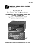
OPERATING INSTRUCTIONS
for the
AUTO-OHM
LOW-RESISTANCE
OHMMETER
Series II
Part Number VIC-60000-S2
Vanguard Instrumentss Company
1710 Grevillea Court
Ontario, California 91761
TEL: (909) 923-9390
FAX: (909) 923-9391
April 2001
Rev. 0
Auto-Ohm Operating Procedures
SAFETY SUMMARY
The following safety precautions must be
observed during all phases of test set-up, test
hookups, testing, and test-lead disconnects.
may seem, never assume anything about the
safety of any test setup.
Ensure the safety of personal by checking
first-hand to eliminate all possible hazards!
Do Not Service or Test Alone
Do not perform test procedures or service
unless another person is also present who is
capable of rendering aid and resuscitation.
Do Not Modify Test Equipment
Because of the added risk of introducing
additional or unknown hazards, do not install
substitute parts or perform any unauthorized
modification to the Auto-Ohm. To ensure
that designed safety features are maintained, it
is recommended that all Auto-Ohm repairs be
performed at Vanguard Instruments Co. or by
an authorized repair-service. Unauthorized
equipment modifications can create unknown
safety hazards and will void the Auto-Ohm
warranty.
Avoid Contact with High Voltage
Because
electrical
utility
station
environments contain high voltages and
currents, there is always the possibility of
personal contact with an unexpected lethal
voltage generated by magnetic induction
and/or electrostatic leakage from nearby live
circuitry. When test units are connected to
deenergized ("dead") power lines, regardless
of how short they are, always discharge the
lines before attaching any test lead. Because
of the possibly deadly consequences of
physical contact with such high-voltage
lines, engineers and technicians must always
treat electrical equipment and hookups as
though a lethal condition will eventually
occur. Therefore, no matter how unlikely it
Follow Exact Operating Procedures
Any deviation from the operating procedures
described in this manual may create one or
more safety hazards, damage the unit or cause
test result errors; Vanguard Instruments Co.
assumes no liability for unsafe or improper
use of the Auto-Ohm.
i
Auto-Ohm Operating Procedures
Table of Contents
Safety Summary............................................................................................................................... i
Table of Contents............................................................................................................................ ii
1.0 Introduction...............................................................................................................................1
1.1 Applicability .............................................................................................................................1
1.2 Supersedure Notice ....................................................................................................................1
1.3 General Description ..................................................................................................................1
1.4 Functional Description..............................................................................................................1
1.5 Furnished Test Accessories.......................................................................................................1
2.0 Auto-Ohm Specifications .........................................................................................................2
3.0 Controls and Display ................................................................................................................3
4.0 Operating Voltages ...................................................................................................................5
5.0 Cable Connections ....................................................................................................................5
6.0 Operating the Auto-Ohm ..........................................................................................................7
6.1.0 Step-by Step Procedures ........................................................................................................7
6.1.1 Precautions.............................................................................................................................7
6.1.2 Preparations ...........................................................................................................................7
6.1.3 Run Test Procedure................................................................................................................7
6.1.4 Contrast Adjustment ..............................................................................................................9
6.1.5 100-Amp Cal Check ..............................................................................................................9
6.1.6 Display Previous Results Procedure ....................................................................................10
APPENDIX A: Auto-Ohm Troubleshooting Guide .....................................................................13
APPENDIX B: Illustration of Test Connectors ............................................................................15
ii
Auto-Ohm Operating Procedures
1.0 INTRODUCTION
1.1 Applicability
This manual applies to Series II of the
Model Auto-Ohm™ (hereafter, Auto-Ohm),
identified by Part Number VIC-60000-S2
made by Vanguard Instruments Company.
A separate manual applies to Series I (the
first design configuration) of the Auto-Ohm.
1.2 Supersedure Notice
This Operator’s manual is the basic issue for
Series II Auto-Ohm and does not supersede
any previously published manual.
1.3 General Description
The Auto-Ohm micro-ohmmeter is made by
Vanguard Instruments Company and
features microprocessor-control for
measuring very low resistances ranging
from 1 micro-ohm to 300 milliohms with
high accuracy. The Auto-Ohm is fieldportable, rugged, and is easily operated by
first-time users having little or no training; it
features a one-knob control and an LCD
alpha/numeric display of the resistance
measured. The one-knob control operation
is logical and simple: Turning the knob
scrolls through a menu of possible options
(which display in sequence) and pressing
the knob activates the selected function. As
its name implies, the Auto-Ohm operation is
automatic, requiring little more from the
user than connecting it to an unknown
resistance and selecting what it is to do and
how the test results are to be presented. The
Auto-Ohm stores the last 3 resistance
measurements, which can be displayed
during test.
1.4 Functional Description
The Auto-Ohm’s operation is based on the
electrical relationships described by Ohm’s
law: R=V/I, where I is a known current and
V is the dc voltage measured across the
unknown resistance (typically, a circuitbreaker’s contacts). Since the current (user
selected) through the unknown resistance is
known and the voltage across the unknown
resistance is read by a precision voltmeter,
the resistance read-out is a direct function of
the voltage being measured. The voltage is
read directly as resistance (translated and
displayed on a digital readout). The dc test
current is selectable in 2-amp steps, from 10
to 100 amperes. Test current is gradually
ramped up and down (automatic function),
which virtually eliminates magnetically
induced transients through the circuitbreaker current transformers. The risk of
inductively tripping a circuit breaker (bus
differential relay) is virtually non-existent.
The Auto-Ohm performs all of these
functions in one simple process. Voltmeter
test leads run separately from the currentbearing test leads to the resistive load; thus,
voltages are measured at the terminals of the
resistance being tested, eliminating any I•R
voltage drop error in the current cables. The
Auto-Ohm test voltage is supplied by a DC
power supply. A precisely regulated
constant-current source ensures measured
voltage is a function of the resistance alone,
and not affected by current-cable resistance
losses. These Auto-Ohm features make very
precise micro-ohm measurements possible
without having to calculate compensations
for current lead resistances errors.
1.5 Furnished Test Accessories
The Auto-Ohm is supplied with one 35-foot
test cable with quick disconnect test plugs at
the unit end and heavy-duty alligator clamps
at the test-load end. Heavy-duty weldingtype C-clamps are available as optional
accessories (these C-clamps allow test lead
connections to a wide variety of bushing
sizes, bus bars, and conductors that require
low-resistance test-lead contacts).
1
Auto-Ohm Operating Procedures
2.0 AUTO-OHM SPECIFICATIONS
Auto-Ohm specifications and leading
particulars are listed in Table 1
.
Table 1. Auto-Ohm Specifications and Leading Particulars
MODEL ...................... Auto-Ohm
PART NUMBER .......... VIC-60000-S2
TYPE ............................. Special-Purpose Test Equipment, Portable, Low Resistance-Ohmmeter
CONFIGURATION...... Second-generation (improved design, superseding original model)
SIZE (inches) .............. 16.8 Wide by 12.6 High by 10.6 Deep
WEIGHT........................ Less than 21 pounds
RESISTANCE
RANGE ......................... 1 micro-ohm to 300 milliohms
TEST CURRENT
RANGE ......................... 10 Amperes to 100 Amperes, Selectable with ±2 ampere increment
DISPLAY ...................... Backlit LCD, 2-lines high by 16 characters Wide
ACCURACY................. ± 1 % of Reading, ± 1 Count, ± 2 micro-ohms
OPERATING
POWER ........................ 8 amps, 90-132 Vac or 200-230 Vac (selectable), 50/60 Hz,
With 10A built in circuit breaker
UNIT PROTECTION... thermal-overload sensor and cutoff
INTERFACE................. RS-232C Connector Port for PC Interface
ENVIRONMENT .......... Operating: 0°C to 55°C; Storage: -40°C to 65°C
FURNISHED ITEMS... One power cord, one 35-ft. test lead cable, one test-cable carrying bag
WARRANTY ................ One-Year Parts & Labor (Post-Warranty Service Contracts Available)
AUTO-OHM SPECIFICATIONS ARE SUBJECT TO UPGRADES AND TO BEING CHANGED WITHOUT PRIOR NOTICE.
2
Auto-Ohm Operating Procedures
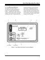
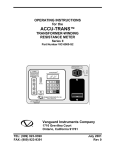
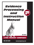
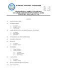
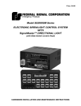
3.0 CONTROLS and DISPLAYS
(See Figure 1 and refer to Table 2.)
The Auto-Ohm controls and displays are
shown in the control-panel illustration,
Figure 1. Pointing leader lines reference
each item with an index number. Each index
number is cross-referenced to a functional
description in Table 2, which describes the
function and purpose of each item on the
control panel. Although the purpose of
these controls and the display may seem
obvious and intuitive, users should become
familiar with them before attempting to use
the Auto-Ohm. First-time users should also
review and become familiar with the Safety
Summary in the front page.
Figure 1. Auto-Ohm Control-Panel Controls and Display
3
Auto-Ohm Operating Procedures
Table 2. Functional Description of Auto-Ohm Controls and Display
Figure 1
Index #
Adjacent Panel Marking
Functional Description
Input power connector with third-wire safety
1
120/240 Vac, 8A, 50- 60 Hz
ground and 10A built-in circuit breaker
LCD; 4-line by 16-character; back-lighted;
2
Displays menus of selections, operator
no marking
entries, and test-measurement results
One-knob control (all Auto-Ohm menus and
3
selections are controlled by this one control
CHANGE
knob). Turning this control knob scrolls
“PUSH”
through different menu options (shown on
TO SELECT
an LCD), which display. Pressing the knob
selects the displayed function, usually
producing a new menu of selectable options.
See Figure 2 for a summary of the step-bystep operating procedures
RS-232C interface port; 9-pin connector;
4
female DB type. The data are set to 19,200
RS-232C
baud, 1 start bit, 8 data bits, and no parity bit;
PIN ................ SIGNAL
2 ................ Rx
3 ................ Tx
5 ................ Signal Gnd
5
6
7
HIGH CURRENT
PRESENT
(resistor symbol)
(None)
4
LED indicator, red; Lights when high test
current is going through the test leads.
Voltage-sensing connector jacks (red).
Current lead connectors (red); Female jacks
for heavy-gauge test cables, which conduct up
to 100 amperes of test current.
Auto-Ohm Operating Procedures
4.0 OPERATING VOLTAGES
The Auto-Ohm operating voltages are
selectable between 90-130Vac, 50/60Hz or
210-240, 50/60Hz. Voltage selection is set
by jumpers on terminal block as shown on
Table 3, below.
Table 3. Voltage Selection
VOLTAGE SELECTION
TERMINAL BLOCK JUMPERS
90-130Vac
Brown to blue & yellow to green
210-240Vac
Blue to yellow
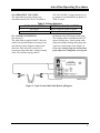
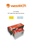
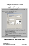
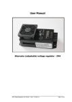
5.0 CABLE CONNECTION
(See Figure 2.)
The Auto-Ohm is supplied with 35-foot test
cables with quick disconnect test plug at one
end and heavy-duty alligator clamps at the
other end. Each test cable consists of a
current-carrying cable and a voltage-sensing
cable. The current-carrying cable is
terminated with a 200-ampere male plug.
The sensing cable is terminated with a 25ampere female plug. Insert current-cable
plugs and voltage-sensing cable plugs into
respective control-panel jacks (Figure 2).
Ensure that voltage plugs are inserted into
jacks adjacent to companion current jacks.
Figure 2. Typical Auto-Ohm Cable Hook-Up Diagram
5
Auto-Ohm Operating Procedures
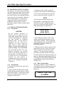
6.0 OPERATING THE AUTO-OHM
(See Figure 3. for step-by-step procedures.)
The Auto-Ohm is operated by just one dualfunction control knob. The operator turns
the control knob to scroll through different
menu selections on the display. When the
desired option appears, it is selected by
simply pressing the control knob like a
pushbutton. Review Figure 3 before
proceeding with the step-by-step procedures
that follow.
6.1 STEP-BY-STEP PROCEDURES
6.1.1 Precautions
CAUTION
Do not measure resistance of
inductive devices, which can create
unsafe high-voltage spikes if the test
current is interrupted by a detached
test lead (created by collapsing
magnetic field). Do not touch or
disconnect any test lead that is
connected to a device under test
while current is being conducted.
Failure to heed this warning can
result in damage to the Auto-Ohm.
The Auto-Ohm measures low, noninductive resistances (e.g., breaker
contacts and bus-bar junctions); If
the resistance of an inductive device
is desired, the use of an Instruments
designed for that purpose is
recommended (such as the Accutrans
made by the Vanguard Instruments
Company).
6.1.2 Preparations
a. Plug the Auto-Ohm power cable into a
power outlet.
b. Insert current-cable plugs and voltagesensing cable plugs into respective controlpanel jacks (Figure 2). Ensure that voltage
plugs are inserted into jacks adjacent to
companion current jacks.
6
c. Attach test-cable clamps to opposite
terminals of the resistive load being tested.
d. To turn on Auto-Ohm power, press the
rocker switch to ON (item 1 in Figure 1).
NOTE
All Auto-Ohm operations begin at the
MAIN MENU, which appears after the
initial boot-up (after configuration and
software revision data display briefly.) The
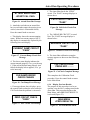
Main Menu display is shown below:
MAIN MENU
<RUN TEST>
Figure 4. Main Menu
e. The main menu displays a list of four
options, which appear in sequence as the
control knob is turned. The four functions
of the Main-Menu list are: RUN TEST, ADJ
CONTRAST, 100A CAL. CHECK, and
PREVIOUS RESULTS.
f. When the option of choice appears in the
Main Menu, press (or “Push”) the control
knob to enter the selection and start that
sequence. The step-by-step operating
procedures to follow describe each of the
selected options in the order listed above. To
run a test, turn the control knob until RUN
TEST appears on the display, then press the
control knob to begin the procedures for
running a test.
6.1.3 Run Test Procedure
The display (SELECT TEST CURRENT)
will appear to the user after the user presses
control knob from the RUN TEST menu,
(Figure 4).
SELECT TEST CUR
<10 AMPS>
Figure 5. Select 10A Menu
Auto-Ohm Operating Procedures
Figure 3. Step-by-Step Procedures for Auto-Ohm Operation
7
Auto-Ohm Operating Procedures
8
Auto-Ohm Operating Procedures
a. This screen prompts the user to select the
desired test current. Test current options are:
10, 25, 50, 100, CUSTOM, and ABORT
TEST. If any of the 10 through 100 amperes
options is the choice, turn the control knob
until that current level displays, then press
the knob to enter that choice (in which case
go to step d). If a smaller increment of
current is desired, select CUSTOM (figure
6) and press the control knob and go to the
next step. The SET CUSTOM CURRENT
menu is show in Figure 7.
Burn-in time range is from 5 to 60 seconds
(in 5-second steps). The default burn-in time
is set for 5 seconds. Turn the control knob
until the desired burn-in time appears in the
display, then press the control knob to enter
that time. Go to the next step.
SELECT TEST CUR
<CUSTOM>
e. This display (above) shows the current
and time that have been selected. If these are
as the user intended, then press the control
knob to accept the selections and begin the
burn-in and measurement sequence. Go to
the next step.
Figure 6. Select Custom Current Menu
b. This menu allows the user to select any
test current from 10 to 100 amperes
50 AMPS
5 SEC
“PRESS” TO RUN
Figure 9. Test Current & Burn-In Time
CUR RAMP:
SELECT TEST CUR
<50 AMPS>
20%
Figure 10. Current Ramp Menu
Figure 7. Custom Current Menu
c. Custom current is defaulted for 50AMPS
(mid point) in this menu. Turn the control
knob until the current of choice displays;
then press the control knob to set the desired
current. The display will now show the
BURN IN TIME menu (Figure 8).
NOTE
Selecting ABORT TEST causes the display
to return to the Main Menu.
BURN IN TIME
<5 SEC>
Figure 8. Burn-In Time Menu
d. This menu selects the amount of time the
burn-in current will be run through the test
load just before its resistance is measured.
f. This display (above) shows the current
ramp percentage (of the test-level current).
The Auto-Ohm will ramp test current from 0
(zero) amperes to the desired test current
level in 3 seconds. The test current is
gradually ramped up and down (an
automatic function), which virtually
eliminates magnetically induced transients
through the circuit breaker current
transformers. When ramp stabilizes at
100%, the next display appears
automatically.
BURNING IN: 02
120.1 MICRO-OHM
Figure 11. Burn-In Menu
g. This display shows the resistance reading
and the remaining burn-in time of the test.
9
Auto-Ohm Operating Procedures
I=100 AMPS
120 MICRO-OHM
Figure 12. Test Current & Resistance
Readings
h. The Auto-Ohm then ramps the test
current back to zero. Figure 12 shows the
final resistance measurement and the test
current at which the resistance was
measured.
i. After the result is examined, press the
control knob and observe that the display
returns to the MAIN MENU. From the
Main Menu another test can be run; or if this
completes the testing requirements, turn off
power to the Auto-Ohm, disconnect test
leads and power cable, and stow them. This
completes the procedure for performing the
RUN TEST procedure.
NOTE
For a “100A test current and 5-second
burn-in test” test, the user can use the
“Quick Test” command as follows:
1. From the RUN TEST menu, hold the
“PUSH” control knob for 2 seconds then
release it. The Auto-Ohm will beep twice
to acknowledge the Quick Test command.
2. Press, then release, the “PUSH” control
knob. The Auto-Ohm will run a 100A test
with a 5- second burn in time.
ADJ CONTRAST on the Main Menu (refer
to paragraph 6.1.2 e).
MAIN MENU
<ADJ. CONTRAST>
Figure 13. Select Adjust Contrast Menu
a. Press knob to select “ADJ. CONTRAST”
mode. The following menu will be shown.
ADJUST CONTRAST
“PRESS”= DONE
Figure 14. Contrast Menu
b. Turn the control knob until the contrast is
suitable for the best operator. When the
contrast is best suited for the operator, press
the control knob; the display returns to the
Main Menu. This ends the contrastadjustment procedure.
6.1.5 Auto-Ohm Cal Check
The purpose of the Calibration Check is to
verify that the Auto-Ohm is operating within
acceptable specifications by running a
functional check on the Auto-Ohm
electronics. From the MAIN MENU, turn
knob to display <100A CAL CHECK> on
the LCD (see Figure 15).
MAIN MENU
<100A CAL CHECK>
6.1.4 Contrast Adjustment
The purpose of this procedure is to adjust
the darkness level of the alpha-numeric
characters shown in the display to produce
the best readability for the ambient light in
the testing area. This begins by selecting
10
Figure 15. 100A Cal Check Menu
a. When this prompt appears, press the
control knob to begin the calibration check.
The following display appears.
Auto-Ohm Operating Procedures
ATTACH SHORT BAR
<START CAL CHK>
Figure 16. Attach Short Bar Prompt
b. Attach the test leads on an unused bus
bar (several inches apart, the spacing is not
critical, since this is a functional check).
Press the control knob to start test.
c. This display shows the current ramping
status. When test current ramps to 100 %,
this display is automatically replaced by the
following test-result display.
CURRENT RAMP CIRCUIT
“PASS”
Figure 17. Current-Ramp Circuit Pass
Message
d. The above status display indicates the
current ramped properly; if so, go to the step
f. If the current did not ramp properly (test
failed) the display below appears; if so, go
to the next step.
f. The Auto-Ohm checks the “ZERO”
circuit. The “PASS” message displays as
shown above.
FSCL CIRCUIT CHECK
“PASS”
Figure 20. Full-Scale Circuit Test
Message
g. The “MEASURE CIRCUIT” is tested
next. The “PASS” message displays is
shown below:
MEASURE CIRCUIT CHCK
“PASS”
Figure 21. Measure Circuit Test Message
h. The Auto-Ohm calibration complete
message appears as shown on the following
display:
CAL CHECK DONE!
PRESS KEY……....
Figure 22. Cal Check Complete Message
CUR RAMP ERROR!
CHECK CABLES
This completes the Calibration Check
procedure. Press the control knob to return
to the Main Menu.
Figure 18. Cur Ramp Error Message
e. If message shown above displays, press
the control knob to abort the test (restart the
Cal Check when the problem is corrected).
ZERO CIRCUIT CHECK
“PASS”
Figure 19. Zero Circuit Test Message
6.1.6 Display Previous Results
The purpose of this procedure is to let an
operator view the last 3 reading stored in the
Auto-Ohm. This procedure begins at the
Main Menu, when PREVIOUS RESULTS
is selected (Figure 23).
MAIN MENU
<PREV RESULTS>
Figure 23. Previous Results Menu
11
Auto-Ohm Operating Procedures
a. Press control knob to select this mode.
The user now can select any of the last three
reading to be displayed. To select the
reading, turn the control knob to one of the
menus.
PREVIOUS RESULTS
<LAST TEST>
PREVIOUS RESULTS
<SECOND TO LAST>
PREVIOUS RESULTS
<THIRD TO LAST>
Figure 24. Select Reading Menus
12
b. When one of the prompts above displays,
press the control knob to display reading.
I= 100AMPS
120.2 MICRO-OHM
Figure 25. Test Record Readout
c. The above display shows the recorded
test resistance (120.2 Micro-ohms) and the
test current level (100 amps) at which it was
measured. When the displayed record of
resistance is reviewed and noted, press the
control knob to return to the Main Menu.
This ends the PREVIOUS RESULTS
procedure.
This concludes the operating procedures for
all Auto-Ohm functions.
Auto-Ohm Operating Procedures
13
APPENDIX A
Auto-Ohm Troubleshooting Guide
Item
1
Symptom
Reading is incorrect.
2
No Test Current.
(Current % read zero)
and resistance reading=0
3
Have test current but
resistance reading = 0.
Possible Problem
1. Poor connection at the test
clips.
2. Broken sensing leads.
Solution
1.Check connections to ensure teeth of
voltage-sensing and current clips are
firmly in contact with the device under
test.
1. No test current going
through the device under test.
2. Inspect sensing cables.
1. Check Connection to the device
under test.
2. Drive circuit not working
1. Broken sensing leads.
2. Run Calibration Test.
1. Inspect sensing leads.
2. Reverse sensing leads.
14
Auto-Ohm Operating Procedures
15
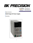
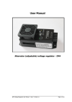
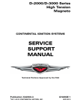
APPENDIX B
C-Clamp
Plastic Clip
Current Connector
Sensing wire Connector
Illustration of plastic quick-disconnect clip, C-clamp, Current Connector, and
Sensing-wire connectors
16
Auto-Ohm Operating Procedures
1710 Grevillea Court. Ontario, CA 91761, USA
Phone 909-923-9390 Fax 909-923-9391
Website: http//www.vanguard-Instrumentss.com
17
Auto-Ohm TM 04/304/01: OAK
18