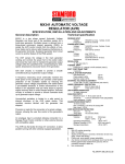
1
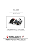
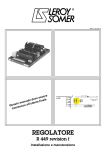
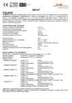
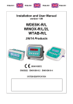
3983 en - 05.2008 / c
s e nt
e
b
us t
m
l
a
nu
s er
a
u
m
d
This o the en
t
(12V - 10A)
J1
R 449
X2
Z1
X1
Z2
E+
E-
+
Isolated DC
power supply
t
~ 10 ohms
Exciter field
VOLTAGE REGULATOR
R 449 revision f
Installation and maintenance
LEROY-SOMER
INSTALLATION AND MAINTENANCE
3983 en - 05.2008 / c
VOLTAGE REGULATOR
R 449 revision f
This manual concerns the alternator A.V.R. which you have just purchased.
We wish to draw your attention to the contents of this maintenance manual. By following certain
important points during installation, use and servicing of your A.V.R., you can look forward to many
years of trouble-free operation.
SAFETY MEASURES
WARNING
Before using your machine for the first time, it is important to
read the whole of this installation and maintenance manual.
All necessary operations and interventions on this machine
must be performed by a qualified technician.
Warning symbol for an operation capable of
damaging or destroying the machine or
surrounding equipment.
Our technical support service will be pleased to provide any
additional information you may require.
The various operations described in this manual are
accompanied by recommendations or symbols to alert the
user to the potential risk of accidents. It is vital that you
understand and take notice of the different warning symbols
used.
Warning symbol for general danger to personnel.
This A.V.R. can be incorporated in a machine
marked C.E.
Warning symbol for electrical danger to personnel.
Note: LEROY-SOMER reserves the right to modify the
characteristics of its products at any time in order to
incorporate the latest technological developments. The
information contained in this document may therefore be
changed without notice.
2
Copyright 2005: LEROY-SOMER
This document is the property of:
MOTEURS LEROY-SOMER
It may not be reproduced in any form without prior
authorization.
All brands and models have been registered and patents
applied for.
LEROY-SOMER
INSTALLATION AND MAINTENANCE
3983 en - 05.2008 / c
VOLTAGE REGULATOR
R 449 revision f
TABLE OF CONTENTS
1 - Introduction to the R 449 ................................................................................................................... 4
1.1 - Application ................................................................................................................................ 4
1.2 - Description ............................................................................................................................... 4
1.2.1 - Power supply connection ............................................................................................. 4
1.3 - Electrical characteristics ........................................................................................................... 6
1.3.1 - Operating diagram ....................................................................................................... 6
1.3.2 - Detection ...................................................................................................................... 7
1.3.3 - Voltage accuracy ......................................................................................................... 7
1.3.4 - Voltage adjustment ...................................................................................................... 7
1.3.5 - Power supply ............................................................................................................... 7
1.3.6 - Output power ............................................................................................................... 7
1.3.7 - Quadrature droop (1F) ................................................................................................. 7
1.3.8 - Frequency compared with voltage (without LAM) ........................................................ 7
1.3.9 - LAM (Load Acceptance Module) characteristics ......................................................... 7
1.3.10 - Typical effects of the LAM with a diesel engine with or without a LAM (U/F only)...... 8
1.3.11 - Gradual voltage return function ................................................................................. 8
1.3.12 - Stability ...................................................................................................................... 8
1.3.13 - Limiting the excitation current Iex .............................................................................. 8
1.3.14 - Protection ................................................................................................................... 9
1.3.15 - Voltage build-up ......................................................................................................... 9
1.3.16 - Power used ................................................................................................................ 9
1.3.17 - De-energising ............................................................................................................ 9
1.4 - Environment ............................................................................................................................. 9
2 - R 726: Regulation of power factor (2F) and mains sensing (3F) ................................................. 10
2.1 - Operating diagram ................................................................................................................. 10
2.2 - Potentiometers ....................................................................................................................... 11
3 - Typical diagrams .............................................................................................................................. 12
3.1 - AREP 1F LV excitation .......................................................................................................... 12
3.2 - AREP 1F MV excitation ......................................................................................................... 13
3.3 - AREP 3F LV excitation .......................................................................................................... 14
3.4 - AREP 3F MV excitation ......................................................................................................... 15
3.5 - 1F LV shunt + booster excitation ........................................................................................... 16
3.6 - 1F LV PMG excitation ............................................................................................................ 17
4 - Commissioning ................................................................................................................................ 18
4.1 - In case of standalone regulation ............................................................................................ 18
4.2 - In case of 1F regulation (parallel operation between alternators) .......................................... 18
4.3 - In case of 2F (power factor regulation) and 3F (voltage match circuit) ................................. 18
5 - Troubleshooting ............................................................................................................................... 20
5.1 - Checking the windings and rotating diodes using a separate excitation ................................ 20
5.2 - Static checking of the regulator .............................................................................................. 20
5.3 - Troubleshooting table ............................................................................................................. 21
5.3.1 - In case of 1F, parallel operation between alternators ................................................ 21
5.3.2 - In case of 2F and 3F .................................................................................................. 23
5.3.3 - Checking the alternator using a separate excitation .................................................. 23
5.4 - Replacing the regulator with a spare voltage regulator .......................................................... 23
6 - Spare parts......................................................................................................................................... 24
6.1 - Designation ............................................................................................................................. 24
6.2 - Technical support service ....................................................................................................... 24
All such operations performed on the A.V.R. should be undertaken by personnel trained in the
commissioning, servicing and maintenance of electrical and mechanical components.
3
INSTALLATION AND MAINTENANCE
LEROY-SOMER
3983 en - 05.2008 / c
VOLTAGE REGULATOR
R 449 revision f
INTRODUCTION TO THE R 449
1 - INTRODUCTION TO THE R 449
- A sensing selection jumper
ST1
(single/3-phase with an external module)
- A response time jumper
ST2
- A frequency selection jumper
ST3
- An external voltage setting jumper
ST4
- A LAM (load adjustment module) jumper
ST5
From R449 Version E number 10,000, this jumper will be
removable.
- A selection jumper 13% 25% LAM
ST10
- Bend at 65 Hz (U/F)
ST11
1.1 - Application
The R 449 voltage regulator is of a shunt type. It is designed
to fit as standard on A50 to A 54 alternators. It can be supplied
with power either by a power VT, or by the AREP field
excitation system, or by a single-phase or 3-phase PMG.
Using the R 726 external module, the regulator can control
the power factor (2F) and can match the alternator voltage to
the mains voltage (3F) prior to synchronisation.
Two fuses (F1 and F2) are connected to this regulator; they
are mounted in the alternator on terminal block C.
Type: gG 10/38 16A 500V.
- ATQ20 (10x38US) 500 VAC UL/CSA
1.2 - Description
Simplified diagram of a potentiometer:
The electronic components mounted in a plastic casing are
sealed with opaque elastomer. Connection is via 2
connectors (male "Faston" lugs 6.3)
The regulator includes:
- A main terminal strip (10 terminals)
- A secondary terminal block (5 terminals)
- A frequency selection terminal block (3 terminals)
- A quadrature droop potentiometer
- A voltage potentiometer
- A stability potentiometer
- A maximum excitation potentiometer
To adjust the potentiometer, check the actual position of the
potentiometer stop.
Stop
J1
J2
J3
P1
P2
P3
P5
0
5
10
1.2.1 - Power supply connection
1.2.1.1 - AREP system
STATOR : 6 or 12-wire (marking T1 to T12)
MAIN FIELD
Aux. windings
T1 T7
T2 T8
T3 T9
T4 T10
T5 T11
T6 T12
Varistor
AREP SYSTEM
5+
Armature
6-
Field
10 Yellow
11 Red
12 Black
9 Green
according to tension
X2 Z1 X1 Z2 E+ E- 0V 110 220 380
ST5
with LAM
ST3
Frequency
without LAM
4 x holes Ø 5.8 x
175 x 115 mm
Quad
droop
P1
60Hz
50Hz
R 449
ST10
LAM
200 mm
140 mm
13 %
T.I.
25 %
S2
Option S1
P5
ST11
ST2
P3
4
Excitation
ceiling
ST4
open
knee-point: 65 Hz
Response
time
Stability
normal
fast
Option
External potentiometer
for adjusting the voltage
ST1
Single-phase
detection
P2
Tension
R731 Option
3-ph. detection
INSTALLATION AND MAINTENANCE
LEROY-SOMER
3983 en - 05.2008 / c
VOLTAGE REGULATOR
R 449 revision f
INTRODUCTION TO THE R 449
1.2.1.2 - PMG system
STATOR : 6 or 12-wire (marking T1 to T12)
MAIN FIELD
PMG SYSTEM
Varistor
Aux. windings
5+
T1 T7
T2 T8
T3 T9
T4 T10
T5 T11
T6 T12
PMG
Armature
6-
Field
14
15
16
according to tension
140 mm
ST5
with LAM
ST3
without LAM
R 449
ST10
LAM
Quad
droop
P1
60Hz
50Hz
Frequency
4 x holes Ø 5.8 x
175 x 115 mm
200 mm
X2 Z1 X1 Z2 E+ E- 0V 110 220 380
13 %
T.I.
25 %
S2
Option S1
Excitation
ceiling
P5
ST11
P3
External potentiometer
for adjusting the voltage
normal
fast
Response
time
ST2
Option
ST4
open
knee-point: 65 Hz
ST1
Single-phase
Stability
P2
Tension
R731 Option
detection
3-ph. detection
1.2.1.3 - SHUNT system
STATOR : 6 or 12-wire (marking T1 to T12)
MAIN FIELD
SHUNT SYSTEM
T1 T7
T8
T3 T9
Varistor
T2
5+
Armature
6-
T4 T10
Field
T11
T5
T6
T12
according to tension
X2 Z1 X1 Z2 E+ E- 0V 110 220 380
ST5
with LAM
ST3
Frequency
without LAM
4 x trous Ø 5.8 x
175 x 115 mm
Quad
droop
P1
60Hz
50Hz
R 449
ST10
LAM
200 mm
140 mm
13 %
T.I.
25 %
S2
Option S1
P5
ST11
ST2
P3
Excitation
ceiling
ST4
open
knee-point: 65 Hz
Response
time
Stability
normal
fast
Option
External potentiometer
for adjusting the voltage
ST1
Single-phase
detection
P2
Tension
R731 Option
3-ph. detection
5
6
1
3 Ph
2
ST4
3
S1 4
TI/CT
S2 5
0V
4
110V
3
220V
2
BORNIER
CONNECTOR J1
BORNIER
CONNECTOR J2
BORNIER
CONNECTOR J3
1
1
AC
DC
1
POTENTIOMETRE TENSION
EXTERIEUR
POTENTIOMETER
EXTERNAL VOLTAGE
POTENTIOMETRE
P1
STATISME
VOLTAGE DROOP
DETECTION
380V SENSING
1
TENSION
VOLTAGE
ST1
1
60Hz
2
50Hz
3
ST3
V/Hz
SOUS-VITESSE
UNDERFREQUENCY
STABILITE
STABILITY
LAM ST5
% LAM ST10
65Hz ST11
P3
PID
ST2
+15V
P5
LIMITE D'EXCITATION
EXCITATION LIMIT
TEMPS
TIME
EXCITATEUR
EXCITER
RESISTANCE
RESISTOR
5
6
TRANSISTOR
DE PUISSANCE
POWER TRANSISTOR
X1
8
X2
10
Z1
9
Z2
7
LEROY-SOMER
INSTALLATION AND MAINTENANCE
3983 en - 05.2008 / c
VOLTAGE REGULATOR
INTRODUCTION TO THE R 449
R 449 revision f
1.3 - Electrical characteristics
1.3.1 - Operating diagram
INSTALLATION AND MAINTENANCE
LEROY-SOMER
3983 en - 05.2008 / c
VOLTAGE REGULATOR
R 449 revision f
INTRODUCTION TO THE R 449
1.3.2 - Detection
1.3.7 - Quadrature droop (1F)
The detection is single-phase and is isolated using an internal
transformer.
Sensing VA: 5VA
J1 connector, input voltages:
Terminals 0-110V voltage range from 85 to 130V
Terminals 0-220V voltage range from 170 to 260V
Terminals 0-380V voltage range from 340 to 520V
Quadrature droop is achieved using a parallel operation CT
(In/1A, 10VA Cl1).
The voltage droop can be adjusted using potentiometer P1.
The voltage range is 5%Un for Pn PF 0.8.
The quadrature droop is at 0 when potentiometer P1 has
been rotated fully anti-clockwise.
1.3.3 - Voltage accuracy
P1
The voltage accuracy is +/- 1%Un, steady state, linear load.
1.3.4 - Voltage adjustment
The voltage is adjusted either using an internal potentiometer
P2, with a voltage range of +/- 10%Un, or using an external
potentiometer (as an option).
The voltage is minimum when internal potentiometer P2 has
been rotated fully anti-clockwise.
1.3.8 - Frequency compared with voltage
(without LAM)
Voltage
Bend
100 %
U/UN
50 Hz
50 Hz
Connecting the external potentiometer:
External potentiometer 470Ω 3W: Voltage range +/- 5%Un
External potentiometer 1kΩ 3W: Voltage range +/- 10%Un
(option). Remove jumper ST4 and connect the external
potentiometer as shown in the diagram below. If a regulator is
built into the terminal box, remove jumper ST10 from terminal
block C and connect the external potentiometer.
Internal
J2
External
Rhe
ST4
60 Hz
Frequency
P2
J2
57.5 Hz
48 Hz
ST4
Voltage setting : ST4
A.F. = Internal
1.3.5 - Power supply
The power can be supplied:
- using 2 independent auxiliary windings integrated in the
alternator stator (AREP excitation)
- using a single or 3-phase power VT
- using a single or 3-phase PMG.
The single or 3-phase voltage must not exceed 240V AC.
1.3.6 - Output power
The output power is 7A 63V under normal conditions and 15A
for 10s under overload conditions.
Hz
60 Hz
1.3.9 - LAM (Load Acceptance Module)
characteristics
The LAM system is integrated in the regulator, as standard it
is active (ST5 with bridge). It can be deactivated by removing
the ST5 bridge. It can be adjusted to 13% or 25% by means
of the ST10 jumper (factory setting 15%).
- Role of the “LAM” (Load Acceptance Module):
On application of a load, the rotation speed of the generator
set decreases. When it passes below the preset frequency
threshold, the LAM causes the voltage to drop by
approximately 13% or 25% and consequently the amount of
active load applied is reduced by approximately 25% to 45%,
until the speed reaches its rated value again.
Hence the LAM can be used either to reduce the speed
variation (frequency) and its duration for a given applied load,
or to increase the applied load possible for one speed
variation (turbo-charged engine).
To avoid voltage oscillations, the trip threshold
for the LAM function should be set approximately 2 Hz below
the lowest frequency in steady state. It is advisable to use the
LAM at 25% for load impacts Š 70% of the genset rated
power.
Voltage
Underspeed and LAM
ST5 disconnected
UN
P2
U/f
LAM
0.87 UN
0
Voltage
48 or 57.5 Hz
ST3
fC
50 or 60 Hz
fN
7
INSTALLATION AND MAINTENANCE
LEROY-SOMER
3983 en - 05.2008 / c
VOLTAGE REGULATOR
R 449 revision f
INTRODUCTION TO THE R 449
1.3.10 - Typical effects of the LAM with a diesel
engine with or without a LAM (U/F only).
1.3.10.1 - Voltage
1.3.12 - Stability
The stability and the response time of the alternator can be
adjusted using potentiometer P3.
Presetting P3 for different types of alternator:
Transient voltage drop
UN
0
5
A50
10
0,9
(U/f)
without LAM
with
LAM
0,8
1s
0
A54
Time
2s
3s
1.3.10.2 - Frequency
Max speed drop
with
LAM
fN
0.9
without
LAM
0.8
1s
0
2s
Time
3s
1.3.10.3 - Power
Load on the
shaft (kW)
LAM
Variation in the load
Load shedding due to "LAM"
1s
0
2s
Time
3s
1.3.11 - Gradual voltage return function
During load impacts, the function helps the genset to return to
its rated speed faster thanks to a gradual increase in voltage
according to the principle:
- If the speed drops between 46 and 50 Hz, the rated voltage
follows a fast gradient as it is restored.
- If the speed drops below 46 Hz, since the engine needs
more help, the voltage follows a slow gradient as it returns to
the reference value.
A51/52
A53
The ST2 jumper modifies the stability. It is closed as
standard. Removing this jumper can in some cases improve
the response time of the alternator (contact Leroy-Somer).
1.3.13 - Limiting the excitation current iex
- The potentiometer P5 is used to adjust the limitation of excitation
Amp. Limitation of the excitation current is active for 10s. After this
period of time, the excitation current is limited to 2A.
The maximum limitation is 15A.
The minimum limitation is when the potentiometer has been
rotated fully anti-clockwise.
In the absence of specification to the contrary, P5 is
positioned at the clockwise limit.
- Static adjustment of the maximum excitation current
For this value, the static adjustment is possible when the
alternator is stopped, which will not endanger the alternator or
the installation.
Disconnect the power supply wires X1,X2 and Z1,Z2 and the
alternator voltage reference (terminal strip J1).
Connect the power supply, 200 to 240V, as shown (X1 and X2:
0-220V). Install a 20 ADC ammeter in series with the exciter
field.
Turn P5 fully anti-clockwise, switch on the power supply
(circuit breaker A).
If the regulator does not discharge, turn potentiometer P2
(voltage) clockwise until the ammeter indicates a stabilised
current.
Switch the power supply off and then on again, turn P5
clockwise until the required excitation current is reached
(limited to 15A), (for precise adjustment contact Leroy-Somer).
Checking the internal protection:
Open the circuit breaker (D): the excitation current must rise
to its preset upper limit, maintain this value for 10s and fall
back automatically to a value less than 1A.
To reset, switch off the power supply using the circuit breaker (A).
Note: After setting the upper excitation limit using this
procedure, re-adjust the voltage.
According to frequency
U
ST3
Drop N ≤ 46 Hz
Drop N > 46 Hz
Time
Mains (Supply 50/60 Hz)
R 449
P5
X2
Z1
X1
Z2
E+
E0V
50Hz 60Hz
ST5
Excit max
ST2
0
P3
P2
ST1
Exciter field
~ 10 ohms
S1 S2
ST4
220V
380V
+
-
A
P1
Voltage
8
A
D
20A DC
INSTALLATION AND MAINTENANCE
LEROY-SOMER
3983 en - 05.2008 / c
VOLTAGE REGULATOR
R 449 revision f
INTRODUCTION TO THE R 449
1.3.14 - Protection
1.4 - Environment
There are two fuses in the power section. They are mounted
externally to the AVR but inside the alternator terminal box.
Rating: gG 10/38 16A 500V
- ATQ20 (10x38US) 500 VAC UL/CSA
- Operating temperature: - 30°C to +70°C
- Storage temperature: - 55°C to + 85°C
- Shocks on the base: 9g for the 3 right-angled directions
- Vibrations: Less than 10Hz: 2mm half peak amplitude
10Hz to 100Hz: 100mm/s
Above 100Hz: 8g
1.3.15 - Voltage build-up
The voltage build-up is automatic (no overvoltage) from the
residual magnetism.
If there is no voltage build-up, a short pulse of continuous
isolated voltage (12VDC), will usually remedy this. Otherwise,
proceed in accordance with the diagram below to re-establish
the residual magnetism:
(12V - 10A)
J1
R 449
X2
Z1
X1
Z2
E+
E-
+
Isolated DC
power supply
t
~ 10 ohms
Exciter field
1.3.16 - Power used
The power used by the R 449 is 30W, when the alternator is
at rated power.
1.3.17 - De-energising
The regulator is de-energised by switching off the voltage
regulation power supply.
Contact rating: 15A, 250V AC
J1
R 449
Aux. windings
X2
Z1
X1
Z2
E+
E-
9
INSTALLATION AND MAINTENANCE
LEROY-SOMER
3983 en - 05.2008 / c
VOLTAGE REGULATOR
R 449 revision f
R 726: REGULATION OF POWER FACTOR (2F) AND MAINS SENSING (3F)
2 - R 726: REGULATION OF POWER FACTOR (2F) AND MAINS SENSING (3F)
The power factor and mains sensing are done by the R726 module.
See the specific manual.
10
FUNCTIONAL DIAGRAM
SYNOPTIQUE DE FONCTIONNEMENT
2.1 - Operating diagram
INSTALLATION AND MAINTENANCE
LEROY-SOMER
3983 en - 05.2008 / c
VOLTAGE REGULATOR
R 449 revision f
R 726: REGULATION OF POWER FACTOR (2F) AND MAINS SENSING (3F)
2.2 - Potentiometers
P1: Potentiometer for adjusting the alternator voltage to the mains voltage (operating mode 3F).
P2: Adjustment of the power factor
P3: Stability
P4: Limitation of the power factor
115 mm
100 mm
U=U
J2
}
}
T3
LED
10
9
8
7
6
5
4
3
2
1
RED "U = U"
T2
GREEN "Cos ϕ"
STAB
P3
P1
LIMIT
P4
T1
Cos ϕ
P2 ST1
ST2
CONTROL OUTPUT
R2 R1
J1
P5
C1
C2
}
MAINS VOLTAGE
(PHASES 2-3)
400
GENERATOR VOLTAGE
100 (PHASES 2-3)
0
}
S2
S1
}
TI / CT / 1A (PHASE 1)
POTENTIOMETERS
1 2 3 4 5 6 7 8 9 10
To A.V.R.
400
100
0
SENSING 50/60 Hz
R 726
P6
P1
MORE GEN VOLTAGE
P2
MORE REACTIVE POWER
P3
STABILITY (// with mains)
P4
P.F. LAG Limit
U
VOLTAGE
Unused terminal
U=U
"Cos ϕ""Cos ϕ"
ADJUSTMENTS / MONITORING
P5 : (-R) = MORE VOLTAGE (single)
+
P6 : (+R) = MORE REACTIVE POWER +
11
INSTALLATION AND MAINTENANCE
LEROY-SOMER
3983 en - 05.2008 / c
VOLTAGE REGULATOR
R 449 revision f
TYPICAL DIAGRAMS
3 - TYPICAL DIAGRAMS
The following diagrams are supplied for information only and are not to be used in place of the actual alternator diagrams.
3.1 - AREP 1F LV excitation
12
LEROY-SOMER
INSTALLATION AND MAINTENANCE
3983 en - 05.2008 / c
VOLTAGE REGULATOR
R 449 revision f
TYPICAL DIAGRAMS
3.2 - AREP 1F MV excitation
13
LEROY-SOMER
INSTALLATION AND MAINTENANCE
VOLTAGE REGULATOR
R 449 revision f
TYPICAL DIAGRAMS
3.3 - AREP 3F LV excitation
14
3983 en - 05.2008 / c
LEROY-SOMER
INSTALLATION AND MAINTENANCE
3983 en - 05.2008 / c
VOLTAGE REGULATOR
R 449 revision f
TYPICAL DIAGRAMS
3.4 - AREP 3F MV excitation
15
LEROY-SOMER
INSTALLATION AND MAINTENANCE
VOLTAGE REGULATOR
R 449 revision f
TYPICAL DIAGRAMS
3.5 - 1F LV Shunt + Booster excitation
16
3983 en - 05.2008 / c
INSTALLATION AND MAINTENANCE
LEROY-SOMER
3983 en - 05.2008 / c
VOLTAGE REGULATOR
R 449 revision f
TYPICAL DIAGRAMS
3.6 - 1F LV PMG excitation
17
LEROY-SOMER
INSTALLATION AND MAINTENANCE
3983 en - 05.2008 / c
VOLTAGE REGULATOR
R 449 revision f
COMMISSIONING
4 - COMMISSIONING
The commissioning principle is the same whatever is the type
of excitation.
4.1 - In case of standalone regulation
- Check fuses F1 and F2 which are situated on terminal block
C in the alternator.
- Check the regulator:
- Check the position of the ST3 jumper (select the frequency,
50 or 60Hz).
- If an external voltage potentiometer is used, disconnect it
from the regulator and install the ST4 jumper (regulator
terminal block J2) or the ST10 jumper, terminal block C in the
alternator terminal box.
- Turn the internal voltage potentiometer P2 on the regulator
fully anti-clockwise.
voltage, if the voltage rises, invert the parallel operation CT.
The voltage quadrature droop is generally 2 to 3% of the rated
voltage.
- The no-load voltages should be identical on all the alternators
intended for parallel operation between each other.
- Connect the alternators in parallel at no load.
- Adjust the setting of voltage P2 or the external voltage
potentiometer of one of the machines, try to eliminate (or
minimise) the circulating stator current between the
machines.
- Do not adjust the voltage further.
- Match the kW power with a minimum load of 30% by
adjusting the drive system speed.
- Adjust quadrature droop potentiometer P1 on one of the
machines to balance or distribute the stator currents.
- If several alternators are in parallel, take one as a reference.
- Set the alternator to its rated speed using the drive system.
- The alternator voltage should rise to a value of 85 to 90%Un.
- Adjust the voltage to the required value using potentiometer
P2.
4.3 - In case of 2f (power factor
regulation) and 3f (voltage match
circuit) (see R726 manual ref. 2440)
- Turn potentiometer P1 fully anti-clockwise.
- Check the wiring between the R 449 and the R 726. (See the
connection diagram).
- Perform an on-load test with power factor = 0.8 or power
factor = 1. The voltage should remain constant within the
limits of the regulator. If it is not stable, see section 13-9.
- Check the information given for the R 726: mains voltage, 2F
contact, 3F contact.
- Stop the alternator and reconnect the
potentiometer, setting it to the centre position.
external
- Set the alternator to its rated speed then, using the external
potentiometer, set the alternator to its rated voltage.
- The regulator set-up phase is now complete.
4.2 - In case of 1f regulation (parallel
operation between alternators)
- The previous settings should be made on each alternator.
- Set the quadrature droop potentiometer to the centre
position and perform an on-load test.
- With a load at power factor = 1, the voltage does not drop or
only drops slightly; with an inductive load, the voltage drops.
This voltage drop is set using quadrature droop potentiometer
P1.
The no-load voltage is always greater than the on-load
18
- If an external voltage potentiometer is used, disconnect it
from the R 726 and add the ST1 jumper (terminals 3 and 4 of
J1) or disconnect it from terminals 25 and 26 of terminal block
C of the alternator and add the ST10 jumper.
- If an external PF potentiometer is used, disconnect it from
the R 726 and add the ST2 jumper (terminals 9 and 10 of J1)
or disconnect it from terminals 29 and 30 of terminal block C
of the alternator and add the ST11 jumper.
- Perform a 1F test.
The test principle is the same as in the case of 1F regulation.
- Matching the alternator and mains voltages prior to
synchronisation (3F):
- If this function is not used, match the voltages by adjusting
the voltage potentiometer.
The following settings are for the R 726.
Close the 3F contact (terminals 5 and 6 of J1 of the R 726 or
terminals 34 and 35 of terminal block C of the alternator). The
red LED lights up. Adjust potentiometer P1 to match the
alternator voltage to the mains voltage.
- Power factor regulation with the alternator synchronised with
the mains (2F):
INSTALLATION AND MAINTENANCE
LEROY-SOMER
3983 en - 05.2008 / c
VOLTAGE REGULATOR
R 449 revision f
COMMISSIONING
The following settings are for the R 726.
When the alternator is in phase with the mains and the mains
and alternator voltages are equal, proceed with
synchronisation. Contact 2F closes when the circuit breaker
is closed. The green LED on the R 726 lights up. Open
contact 3F and remove the mains voltage reference.
Preset the PF potentiometer P2 to 5 and limit potentiometer
P4 to 3.5.
Without supplying kW power to the mains, the reactive
current of the alternator should be at or around 0.
Increase the kW power. When it reaches 50% of the rated
power, adjust potentiometer P4 to obtain a PF of 0.9 LAG
(inductive) on the alternator. The range is then 0.7 LAG PF
(inductive) (P2 turned fully clockwise) to 0.95 LEADING
(capacitive) (P2 turned fully anti-clockwise).
Adjust P2 to obtain the required power factor value.
Increase the kW power until it reaches the rated power. The
PF should remain constant.
If it becomes unstable, adjust potentiometer P3 on the R 726
or potentiometer P3 on the R 449.
- Stop the alternator
potentiometers.
and
reconnect
the
external
19
INSTALLATION AND MAINTENANCE
LEROY-SOMER
3983 en - 05.2008 / c
VOLTAGE REGULATOR
R 449 revision f
TROUBLESHOOTING
5 - TROUBLESHOOTING
5.1 - Checking the windings and
rotating diodes using a separate
excitation
During this procedure, you must check that the alternator is
not connected to any external loads and examine the terminal
box to check that the connections have been made correctly.
Do not perform dielectric tests without disconnecting the module and associated AVR.
RISK OF DESTRUCTION
- Stop the generator, disconnect and isolate the regulator
wires.
ASSEMBLY B
Variac
- There are two possible assemblies for a separate excitation:
see the diagrams below.
50
90
10
80
20
70
- Assembly A: Connect the DC supply (2 batteries in series)
in series with a rheostat of approximately 20 ohms/500W and
a diode on both field winding wires (5+) (6-)
100
0
Diode 5 A
-
-
AC
220 V
ASSEMBLY A
6 - Exciter field
5+
Rh. 20 - 500 W
+
Battery 12V
- Assembly B: Connect a "variac" variable power supply and
a diode bridge to both field winding wires (5+) (6-).
5+
+
60
30
40
6 - Exciter field
Diode
5A
5.2 - Static checking of the regulator
If the regulator operates correctly during a static test, this
does not necessarily mean that it will operate correctly under
real conditions.
If the regulator fails the static test, it can be concluded without
doubt that the regulator is faulty.
Connect a test bulb in accordance with the diagram.
The power supply voltage must be between 200 and 240V.
The voltage of the bulb is 230V. The power of the bulb will be
less than 100W.
- Turn potentiometer P2 fully anti-clockwise.
- These two systems must be compatible with the excitation
rating of the machine (see the nameplate).
- Switch the regulator on; the bulb must briefly light up and
then go out.
- Run the generator set at its nominal speed.
- Slowly turn the voltage potentiometer clockwise, to the right.
- Gradually increase the power supply current of the field
winding by adjusting the rheostat or variac and measure
output voltages L1, L2, L3, checking the no-load excitation
voltages and currents. (See the alternator nameplate or ask
Leroy-Somer for the test log).
- When turned fully clockwise, the bulb lights up continuously.
- If the output voltages are at their rated values and are
balanced at < 1% for the given excitation value, the machine
is operating correctly and the fault is due to the regulation part
(regulator, wiring, sensing, auxiliary windings).
- At the regulation point, turning the voltage adjustment
potentiometer slightly in one direction or the other should
make the bulb light up or go out. If the bulb is either lit
continuously or does not light up at all, the regulator is faulty.
- Perform one test supplying the regulator via terminals X1
and X2, then another supplying it via terminals Z1 and Z2.
According to frequency
ST3
200 - 240 V
(220 V)
R 449
P5
X2
Z1
X1
Z2
E+
E0V
50Hz 60Hz
ST5
ST2
P3
When the alternator is stopped, mains voltage may
still be present at the module voltage sensing
terminals.
20
P2
ST1
Mains
(Supply
50/60 Hz)
P1
S1 S2
Voltage
ST4
220V
380V
V
300 V :
DC
INSTALLATION AND MAINTENANCE
LEROY-SOMER
3983 en - 05.2008 / c
VOLTAGE REGULATOR
R 449 revision f
TROUBLESHOOTING
5.3 - Troubleshooting table
- Before taking any action on the R 449 or the R 726, pay careful attention to the positions of the potentiometers and the jumpers.
5.3.1 - In case of 1F, parallel operation between alternators
Symptom
Absence of voltage on
start-up, at no load.
Voltage too high and
adjustment potentiometer
not operating.
Voltage too high, but
adjustable by the
adjustment potentiometer.
Voltage too low, but
adjustable by the
adjustment potentiometer.
Probable causes
Solutions
- No residual magnetism or polarity inversion
between the excitation output and the exciter
input.
- Voltage built-up is required.
- De-energising contacts open.
- Close this contact.
- The speed is less than the rated speed.
- Adjust the speed.
- Connection lost between the regulator and the
exciter.
- Check the wiring.
- Alternator loaded or short-circuited.
- Remove the load from the alternator.
- External potentiometer connected incorrectly
- Check the wiring.
- Faulty regulator
- Test it or change it.
- Faulty exciter or rotating diode bridge
- Check the exciter and the diodes.
- Fuses blown.
- Replace the fuses.
- Incorrect voltage at the sensing terminals.
- Check the wiring of the 0, 110V, 220V, 380V
terminals on terminal block J1.
- Loss of sensing.
- Check the wiring.
- The external potentiometer has an incorrect
value.
- Set a potentiometer with the correct value.
- Faulty regulator.
- Test it or change it.
- Voltage potentiometer set too high.
- Adjust voltage potentiometer P2 or the external
potentiometer.
- Regulator sensing incorrect.
- Check the wiring and the sensing value, at 0V
and 110V, 220V, 380V terminals.
- Regulator faulty.
- Test it or change it.
- ST3 and ST4 jumpers.
- Check the presence of the ST3 and ST4
jumpers.
- The speed is too low.
- Set to the correct speed.
- Exciter and rotating diodes.
- Check the exciter and the rotating diodes.
21
LEROY-SOMER
INSTALLATION AND MAINTENANCE
3983 en - 05.2008 / c
VOLTAGE REGULATOR
R 449 revision f
TROUBLESHOOTING
Symptom
Incorrect regulation.
Voltage unstable.
Response time too long.
Considerable drop in
voltage, on-load.
Probable causes
Solutions
- Distortion of the waveform, non-linear load.
- Contact Leroy-Somer.
- Unbalanced load.
- Balance the load or change the sensing points.
- The speed is not at the correct value.
- Adjust the speed.
- Exciter or rotating diodes faulty.
- Check the exciter and the rotating diodes.
- Faulty regulator.
- Test it or change it.
- Frequency unstable.
- Check the stability of the drive system speed.
- Secondary sensing of a transformer supplying
other devices.
- Provide separate sensing for the alternator.
- Stability potentiometer P3 is incorrectly set.
- Adjust stability potentiometer P3.
- Faulty regulator.
- Test it or change it.
- Stability adjustment.
- Adjust stability potentiometer P3 and the ST2
jumper.
- Speed regulator response too long.
- Adjust the stability of the speed.
- Vectorial composition fault between the voltage - Check the wiring of the sensing and parallel
and the current.
operation CT.
- The parallel operation CT ratio is incorrect.
kVAR not stable between - Quadrature droop potentiometer needs
alternators (reactive current adjusting.
circulation).
- The no-load voltages are not identical.
- Correct the CT ratio.
- Adjust the quadrature droop potentiometer.
- Check that all the alternators have the same
no-load voltage value.
- Phases not connected to the sensing correctly.
- Check the sensing wiring.
- The CT is not on the correct phase.
- Check the position of the parallel operation CT.
Warning : after operational testing, replace all access panels or covers.
22
INSTALLATION AND MAINTENANCE
LEROY-SOMER
3983 en - 05.2008 / c
VOLTAGE REGULATOR
R 449 revision f
TROUBLESHOOTING
5.3.2 - Example of 2F and 3F
Symptom
Incorrect regulation of PF,
PF potentiometer not
operating.
Probable causes
Solutions
- Vectorial composition fault between the sensing - Check the sensing wiring and the parallel
operation CT.
voltage and the stator current.
- Change the module.
- R 726 faulty.
- R 726 ST2 jumper missing.
Check the wiring, in particular the wires
- Wiring fault between the R 449 and the R 726. -between
1 and 2 of terminal block J1 on the
R 726.
PF range incorrect.
- Settings on potentiometers P2 incorrect.
- Reset the range as shown above.
The LEDs will not light up.
- Contacts 2F and 3F missing.
- Check the wiring.
Cannot adjust the voltage
matching circuit.
- The sensing voltage is incorrect or incorrectly
connected.
- Check the wiring and the value of the voltage.
5.4 - Replacing the regulator with a
spare voltage regulator
Warning : after operational testing, replace all
access panels or covers.
- Set the potentiometers and the jumpers in the same way as
the original regulator.
5.3.3 - Checking the alternator using a
separate excitation
- The alternator is tested at no load.
- Disconnect the R 449 and R 726 and the entire excitation
system of the alternator.
- Connect a 24V 5A variable DC supply to the exciter field
wires.
Apply a direct current to the exciter to obtain the rated
voltage.
- Check all the alternator parameters:
Stator voltage, field winding voltage, AREP or regulator
power transformer voltages, sensing voltage at the regulator
terminal
block.
- All these parameters should be checked against the
alternator characteristics.
23
LEROY-SOMER
INSTALLATION AND MAINTENANCE
VOLTAGE REGULATOR
R 449 revision f
SPARE PARTS
6 - SPARE PARTS
6.1 - Designation
Description
A.V.R.
Type
R 449
Code
AEM 220 RE 030
6.2 - Technical support service
Our technical support service will be happy to provide any information you require.
When ordering spare parts, you should indicate the complete
machine type, its serial number and the information indicated
on the nameplate.
Part numbers should be identified from the exploded views
and their description in the parts list.
Our extensive network of "service stations" can dispatch the
necessary parts without delay.
To ensure correct operation and the safety of our machines,
we recommend the use of original manufacture spare parts.
In the event of failure to comply with this advice, the
manufacturer cannot be held responsible for any damage.
24
3983 en - 05.2008 / c
LEROY-SOMER
INSTALLATION AND MAINTENANCE
3983 en - 05.2008 / c
VOLTAGE REGULATOR
R 449 revision f
NOTES
25
LEROY-SOMER
INSTALLATION AND MAINTENANCE
VOLTAGE REGULATOR
R 449 revision f
NOTES
26
3983 en - 05.2008 / c
LEROY-SOMER
INSTALLATION AND MAINTENANCE
3983 en - 05.2008 / c
VOLTAGE REGULATOR
R 449 revision f
NOTES
27
MOTEURS LEROY-SOMER 16015 ANGOULÊME CEDEX - FRANCE
338 567 258 RCS ANGOULÊME
S.A. au capital de 62 779 000 ¤
www.leroy-somer.com