1
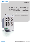
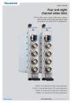
User manual
Four and eight
channel video modems
CFO-OPX series consist of fibre optic modems
which provide a high quality and losless video
transmission for variety of CCTV applications.
CEV 4/8 channel bidi user manual, 59300290, rev004
Contents
CEV – CWDM Optical Transmitter & Receiver............................................................................................................ 1
Introduction......................................................................................................................................................... 1
CEV – Video Modem Front Panel............................................................................................................................. 2
Frame installation................................................................................................................................................ 2
Video connections and indicator leds................................................................................................................. 2
CSX Multiplexer operation.................................................................................................................................. 2
S-video operation................................................................................................................................................ 2
Stand-alone installation....................................................................................................................................... 3
Data connections................................................................................................................................................ 4
Audio connection................................................................................................................................................ 5
Management (mgmt) data connection................................................................................................................ 6
Contact closure loop (CCL) connection.............................................................................................................. 7
Ethernet Bridge connection................................................................................................................................. 8
Video Source Alarm (VSA)................................................................................................................................. 9
Link Source Alarm (LSA)..................................................................................................................................... 9
Link status and module indicator leds............................................................................................................... 10
Fibre connection............................................................................................................................................... 11
Optical signal levels.......................................................................................................................................... 11
Command Line Interface - CLI................................................................................................................................ 12
General............................................................................................................................................................. 12
System requirements for CLI............................................................................................................................ 12
User groups....................................................................................................................................................... 12
Connection methods - Serial connection.......................................................................................................... 13
Connection methods - TCP/IP.......................................................................................................................... 14
Detailed descriptions of commands.................................................................................................................. 15
Commands in brief............................................................................................................................................ 15
How to use the CLI commands......................................................................................................................... 15
TFTP, Trivial File Transfer Protocol................................................................................................................... 28
SNMP support................................................................................................................................................... 29
Technical Specifications......................................................................................................................................... 30
Copyright acknowledgements........................................................................................................................... 31
WEEE directive................................................................................................................................................. 31
CEV 4/8 channel bidi video modem user manual rev004
CEV – CWDM Optical Transmitter & Receiver
CEV singlemode 4 and 8 channel video modem for unidirectional video and bi-directional audio, data, contact
closure and Ethernet transmission, In-band management
Welcome, and thank you for purchasing Teleste’s CFO Products.
Vx8 Dx3 Ax2 C x1C Ex1 M
The CEV is a basic building block for multi-channel video transmission
system providing uni-directional transmission of 4 / 8 uncompressed
video channels with three bi-directional data, two audio, one contact
closure and one Fast Ethernet signals over one singlemode fibre.
gmt
gmt
Vx4 Dx3 Ax2 C x1C Ex1 M
Introduction
PAL, NTSC and SECAM video formats are supported to provide a transparent video transmission. It is also possible to transmit 2 / 4 S-video
channels that comprises of separate luminance (Y) and chrominance (C)
signals. Video interface is also compatible with CSX series multiplexers.
All common data protocols are supported as well and are easily configurable by terminal software interface.
Optical transmission is based on class 1M laser operation. The multiplexed data stream of 1.2 / 1.9 Gbps enables a full quality and a zerodelay (latency free) video transmission in one singlemode fiber over distances of tens of kilometres.
Management connection between CEV units and e.g. laptop or PSION is
based either on a serial data, or a TCP/IP communication by means of
any terminal type program. Management user interface follows the general guidelines of a Command Line Interface type operation (CLI) and it
is meant for configuration and controlling of CEV units.
The CEV units complies to ITU G.694.2 CWDM wavelength grid with 20
nm spacing. Available ITU CWDM channels for CEV units are C11...C18.
All CEV units are compatible with all CFO rack systems. Stand-alone
options are available with the CMA module adapter and a separate
mains adapter.
CEV 4/8 channel bidi video modem user manual rev004
3
CEV – Video Modem Front Panel
7
CAUTION:
THESE OPTICAL UNITS USES CLASS 1M LASER DIODE.
DO NOT STARE INTO BEAM OR VIEW DIRECTLY WITH OPTICAL INSTRUMENTS. APPLICABLE STANDARD
IEC60825-1: 2001
OPTICAL TRANSMITTER
2
DATA / CCL
8
VIDEO 1
DATA
1
VIDEO 2
4
AUDIO
Frame installation
The CEV unit is to be pushed along the guide rails into the installation
frame (e.g. CSR216 or 316 series) and secured with the four locking
screws. The unit can be freely positioned in any slot in the frame.
(Alarm card slot excluded). The empty positions in the frame should be
blanked off with cover plates. The supply voltage is to be provided by
a CPS384 or CPS390 power supply unit.
VIDEO 3
MGMT
3
VIDEO 4
ETHERNET BRIDGE
LINKSTATUS
MODULE
5
9
6
Video connections and indicator leds
CEV-4T optical transmitter.
(Same information applies respectively to
receiver unit CEV-4R)
7
OPTICAL TRANSMITTER
3
4
DATA / CCL
VIDEO 2
VIDEO 6
VIDEO 3
VIDEO 7
DATA
VIDEO 5
VIDEO 4
VIDEO 8
MODULE
ETHERNET BRIDGE
LINKSTATUS
5
9
6
CEV-8T optical transmitter.
(Same information applies respectively to
receiver unit CEV-8R)
1) DATA 1 & CCL connector (RJ-45 female)
2) DATA 2 & 3 connector (RJ-45 female)
3) AUDIO 1 & 2 connector (RJ-45 female)
4) Management connector (RJ-45 female)
5) Optical input/output (SC/APC 8°)
6) Handle (with unit information)
7) Locking screw (4 pcs)
8) Video input (BNC female) and video indicator led
9) ETHERNET BRIDGE connector
(RJ-45 female)
See further information on dedicated
sections.
4
CSX Multiplexer operation
Alternatively the video channel can be used for CSX series multiplexer
operation --> multiplexed audio/data/contact closure transmission.
No extra adjustments are needed.
S-video operation
AUDIO
2
8
VIDEO 1
MGMT
1
The impedance of the video connection (BNC female) is 75 Ω.
The nominal input/output level is 1 Vpp. Video connection is equipped
with the dual colour VIDEO led on the front panel. See table below for
explanation of VIDEO indicator led’s lights.
It is also possible to transmit four S-video signals that comprises separate luminance (Y) and chrominance (C) signals. This, however, uses two
channels per one transmission channel. Connect Y and C signals to any
of video inputs. Make sure that the Y and C connections are corresponding both at transmitter and receiver. No extra adjustments are needed.
Colour
Status
Green
A signal is present and in nominal level
Yellow
No video signal, or the video level is too low
No light
Video input/output is disabled (via management)
VIDEO indicator operation.
CEV 4/8 channel bidi video modem user manual rev004
Stand-alone installation
The CEV unit can be installed for stand-alone use by using a CMA025
(installation for 10HP wide CFO series units, CEV4) or CMA035 (installation for 15HP wide CFO series units, CEV8) module adapter. The
module should be mounted to a vertical surface.
The 12V DC supply voltage is supplied by the means of a separate
mains adapter with a regulated output, (e.g. CPS251). Please refer to
separate documention for module adapters and mains adapters.
2
1
Power supply connection.
CMA025 module adapter with CIK002 rear mounting kit.
1) CMA025 module adapter
2) CIK002 rear mounting kit
CEV 4/8 channel bidi video modem user manual rev004
5
1
DATA / CCL
8
8
Data connections
Led 2
(Data 1)
Led 3
(Data 2)
The CEV link contains three independent bi-directional data channels
(TX <--> RX). The connector is type RJ-45 female. Supported data
modes for data channel 1 & 2 are RS232, RS422, RS485-2w and
RS485-4w. Data channel 3 is fixed for RS232 mode only. A recommended cable for DATA connection is CIC603 (RJ-45/open wires,
2 meters). The desired data mode for data channel 1 & 2 can be set via
management connection (see page 12). The default factory settings are;
data ch1 RS485-2w + dwell time 75µs and data ch2 RS232.
DATA
Led 1
(CCL)
1
Led 4
(Data 3)
DATA/CCL and DATA connectors and
indicator LEDs.
Pin
Colour
1
White / green stripe
2
Green
3
White / orange stripe
4
Blue
5
White / blue stripe
6
Orange
7
White / brown stripe
8
Brown
1
2
3
4
Signal
RS232
RS422
RS485-2w
1
Data 1
in -
in / out -
in -
2
Data 1
in
in +
in / out +
in +
3
Data 1
out
out -
out -
4
CCL in
out +
out +
5
Ground
6
Data 1
7
CCL out A
8
CCL out B
Pin
Signal
1
Data 2
2
Data 2
3
Data 2
Status
4
NC
Green
CCL is on
5
Ground
Yellow
CCL is off
6
Data 2
Green
Channel input active
7
Data 3
in
Yellow
Channel input passive
8
Data 3
out
No light
Channel disabled
Green
Channel input active
Yellow
Channel input passive
Data mode
Input termination options
No light
Channel disabled
RS232
None
Green
Channel input active
Yellow
Channel input passive
RS422
No term (with failsafe, 10 kΩ line biasing)
Line termination (120 Ω)
No light
Channel disabled
RS485 - 2w
No term (with failsafe, 10 kΩ line biasing)
+ Dwell time adjustable 0...65535µs
Hard bias (forced 680 Ω line biasing)
Line termination (120 Ω)
RS485 - 4w
No term (with failsafe, 10 kΩ line biasing)
Hard bias (forced 680 Ω line biasing)
Line termination (120 Ω)
Colour
RS485-4w
DATA/CCL connector’s pinout.
CIC603 cable’s pinout / wire colors
(RJ-45 male / open wires).
Led
Pin
DATA/CCL and DATA connection’s
indicator operation.
RS232
RS422
RS485-2w
RS485-4w
in -
in / out -
in -
in
in +
in / out +
in +
out
out -
out -
out +
out +
DATA connector’s pinout.
Data input termination options for data channels 1 & 2.
See CLI description for configuration settings (dataterm and databias).
6
CEV 4/8 channel bidi video modem user manual rev004
8
Led 1
(Audio 1)
AUDIO
1
Led 2
(Audio 2)
AUDIO connector.
Pin
Colour
1
White / green stripe
2
Green
3
White / orange stripe
4
Blue
5
White / blue stripe
6
Orange
7
White / brown stripe
8
Brown
CIC603 cable’s pinout / wire colors
(RJ-45 male / open wires).
Audio connection
The CEV link contains two bi-directional audio channels (TX <--> RX),
which can be used for one stereo audio or two mono audio purposes.
The AUDIO interface supports both balanced (both channels separately) and unbalanced wiring. The default audio input impedance is
set to high impedance (>10 kΩ). Alternatively the audio input impedance can be set to 600 Ω (this setting requires balanced wiring for both
channels). The audio output impedance is set to 10 Ω. The connector
type is a RJ-45 female. A recommended AUDIO cable is CIC603
(RJ-45/open wires). The audio channels operates independently, i.e.
despite the absence of all video signals.
Pin
Balanced signal
Unbalanced signal
1
Audio 1 out -
GND
2
Audio 1 out +
Audio 1 out
3
Audio 2 out -
GND
4
Audio 2 in +
Audio 2 in
5
Audio 2 in -
GND
6
Audio 2 out +
Audio 2 out
7
Audio 1 in -
GND
8
Audio 1 in +
Audio 1 in
AUDIO connector’s pinout. (Note! RJ45 connector shield is grounded).
Led
1
2
Colour
Status
Green
Audio 1 signal level is good
Yellow
Audio 2 signal level is too low
Green / Yellow blinking
Audio 1 signal level is too high
No light
Audio 1 channel is disabled
Green
Audio 2 signal level is good
Yellow
Audio 2 signal level is too low
Green / Yellow blinking
Audio 2 signal level is too high
No light
Audio 2 channel is disabled
Audio (input) connection’s indicator operation.
CEV 4/8 channel bidi video modem user manual rev004
7
8
Led 1
(mode)
Management (mgmt) data connection
MGMT
1
Access to the device management is provided either with serial data
(RS-232) or with TCP/IP connection. The management connector type
is a RJ-45 female. When using TCP/IP connection any type of CAT5
Ethernet cable can be used (interface has auto feature). Connection
type is 10/100Base-TX with autonegotiation enabled (default).
Led 2
(status)
Mgmt connector.
Pin
Signal
1
Ethernet mgmt (Tx + / Rx +)
2
Ethernet mgmt (Tx - / Rx -)
3
Ethernet mgmt (Rx + / Tx +)
4
Not used
5
Serial mgmt (RS232 in)
6
Ethernet mgmt (Rx - / Tx -)
7
Not used
8
Serial mgmt (RS232 out)
Shield
Ground
Mgmt connector’s pinout.
RJ-45
D9
RJ-45
male
male
female
1
-
1
2
-
2
3
-
3
4
-
-
5
2
-
6
-
6
7
-
-
8
3
-
Shield
5
-
CIC505 connector pinout
(RJ-45 male/D9 male/RJ-45 female).
A simultaneous management session using both connection types can
be done by means of CIC505 connection adapter.
CIC505 connection adapter. (Allowing simultaneous serial and TCP/IP
connection via MGMT connector).
Led
1
2
Colour
Status
Green
Full duplex
Green blinking
Collisions in data
No light
Half duplex
Yellow
Mgmt link up
Yellow blinking
Ethernet mgmt active
No light
Mgmt link down
Mgmt connection’s indicator operation.
PC/PSION
D9 female
RJ-45 male
CEV
Receive data
2
8
Mgmt output
Transmit data
3
5
Mgmt input
System ground
5
Shield
Ground
Management cable (CIC505) pinout (D9 female / RJ-45 male).
8
CEV 4/8 channel bidi video modem user manual rev004
4
1
DATA/CCL
7 5
CCL
input
Led 1
(CCL)
8
CCL
output
Led 2
(Data 1)
CCL connector. CCL led indicates status
of CCL input/output signal.
Pin
Colour
Contact closure loop (CCL) connection
The CEV link contains one bi-directional contact closure channel line
(TX <--> RX). The CCL input is a normal short circuit on/off - signal
between connector’s contact pins 4 and 5 (max loop resistance approximately 120 Ω). The CCL output is a normal relay on/off - signal between
connector’s contact pins 7 and 8 (maximum switching 30 V DC/V AC,
1A). The connector type is a RJ-45 female. The recommended cable
for CCL use is CIC603 (RJ-45/open wires).
The CCL output channel can be alternatively configured for VSA
(video source alarm) or LSA (link source alarm) usage via management
connection (see page 9).
1
White / green stripe
2
Green
3
White / orange stripe
4
Blue
5
White / blue stripe
6
Orange
2
Data 1
7
White / brown stripe
3
Data 1
8
Brown
4
CC1
in
5
Ground
CIC603 cable’s pinout / wire colors
(RJ-45 male / open wires).
Pin
Signal
1
Data 1
RS232
RS422
RS485-2w
RS485-4w
in (-)
in / out (-)
in (-)
in
in (+)
in / out (+)
out
out (-)
out (-)
out (+)
out (+)
6
Data 1
7
CCL/VSA/LSA
out A
8
CCL/VSA/LSA
out B
in (+)
DATA 3 & CCL connector’s pinout.
Led
1
Colour
Status
Green
CCL output is closed (pin 4 to ground)
Yellow
CCL output is open
CCL indicator operation.
CEV 4/8 channel bidi video modem user manual rev004
9
Led 2
(mode)
Ethernet Bridge connector.
8
Ethernet
1
Led 1
(status)
Ethernet Bridge connection
The ETHERNET BRIDGE interface provides one Ethernet 10/100BaseTx port for any IP device requiring Ethernet connectivity. The connector
type is a RJ-45 female. Default port configuration is with autonegotion feature enabled.
Note! It is also possible to disable ETHERNET BRIDGE
via management.
Pin
Signal
1
Tx + / Rx +
2
Tx - / Rx -
3
Rx + / Tx +
4
5
6
Rx - / Tx -
7
8
Ethernet Bridge connector’s pinout.
Led
1
2
Colour
Status
Yellow
Link up
Yellow blinking
Link active and traffic detected
No light
Link down or disabled
Green
Full Duplex
Green blinking
Collision activity
No light
Half Duplex
Ethernet bridge interface’s indicator operation.
10
CEV 4/8 channel bidi video modem user manual rev004
Video Source Alarm (VSA)
The CCL output channel can be alternatively configured for Video Source
Alarm (VSA) monitoring. Instead of normal CCL use, the CCL output can
be used to provide a VSA signal if a loss of video signal occurs.
When VSA mode is enabled at transmitter and if video signal is missing
(e.g. a camera malfunction, link otherwise operates normally), the CCL
output pins are closed. Using VSA at just one end of the link enables the
opposite path to be used for standard CCL operation (simplex). In case
when VSA is enabled both at transmitter and receiver, the CCL
channel is no longer available for any other use. When VSA is disabled
the CCL channel is available for normal use in both directions. The VSA
mode can be set on/off via management connection. See page 27 for
more information how to configure VSA operation.
Note! Enabling VSA on any channel overrides normal contact
closure functionality.
Led
1
Colour
Status
Green blinking
Video OK
Yellow blinking
Video missing / VSA active
CCL indicator operation when VSA is enabled.
Link Source Alarm (LSA)
The CCL output channel can be alternatively configured for Link
Source Alarm (LSA) monitoring. Instead of normal CCL use, the CCL
output can be used to provide a LSA signal if a loss of optic link occurs.
When LSA mode is enabled at transmitter and if optical communication
is disturbed seriously (link fail alarm due to e.g. a cable break or damage, a laser fail etc), the CCL output pins are closed. Using LSA at just
one end of the link enables the opposite path to be used for standard
CCL operation (simplex). In case when LSA is enabled both at transmitter and receiver, the CCL channel is no longer available for any
other use. When LSA is disabled the CCL channel is available for
normal use in both directions.
The LSA mode can be set on/off via management connection.
See page 22 for more information how to configure LSA operation.
For a practical use the LSA/CCL operation can be also used to control
an optical switch in fibre redundant applications.
Note! Enabling LSA overrides normal contact closure
and VSA functionality.
Led
1
Colour
Status
Green blinking
Link OK
Yellow blinking
Link missing / LSA active
CCL indicator operation when LSA is enabled.
CEV 4/8 channel bidi video modem user manual rev004
11
Link status and module indicator leds
The CEV contains LINK STATUS and MODULE indicators which inform
generic status of unit.
Colour
Status
Green
Optical signal level is adequate and syncronization on link
level is achieved
Blinking Green
Link alarm from remote end: No optical signal received
Yellow
Optical signal is missing or input level is too low
LINK STATUS indicator operation.
Colour
Status
Green
Normal operation
Red
Supply voltage is not in the permitted range or
a hardware failure
MODULE indicator operation.
TRANSMITTER
RECEIVER
X
AUDIO
DATA
DATA
X
VIDEO 2
VIDEO 2
Video is not received ok, return link is up:
MGMT
X
X
VIDEO 4
ETHERNET BRIDGE
LINKSTATUS
MODULE
LINK STATUS =
YELLOW
(No reception)
VIDEO 4
LINKSTATUS
MODULE
Video is not received ok, both directions
are down. If MODULE is not showing
alarm, fault is on fibre:
LINK STATUS =
YELLOW
(No reception)
VIDEO 3
MGMT
LINK STATUS =
BLINKING GREEN
(Status received from TX)
VIDEO 3
VIDEO 1
ETHERNET BRIDGE
VIDEO 1
DATA / CCL
LINK STATUS =
BLINKING GREEN
(Status received from TX)
LINK STATUS =
YELLOW
(No reception)
AUDIO
DATA / CCL
Video is received ok, return link is down:
LINK STATUS =
YELLOW
(No reception)
LINK STATUS indicator operation example.
12
CEV 4/8 channel bidi video modem user manual rev004
ITU Ch
Wavelength
11
1470 nm
12
1490 nm
13
1510 nm
14
1530 nm
15
1550 nm
16
1570 nm
17
1590 nm
18
1610 nm
Available ITU G.694.2 wavelength
channels for CEV units.
Fibre connection
CEV video modems are designed to operate on ITU specified CWDM
optical channels. Next to the handle each model is having a label stating
the operational ch, optical output level and the minimum input level.
The optical connector type is SC/APC 8°.
When installing the fibre optic cable, do not exceed the minimum
bending radius when connecting cable to the system.
For correct optical operation ensure that:
* Protect opened connectors always with dustcaps.
* Use only 8° angle polished SC/APC connectors, other connector
types will damage the interface.
* Clean all connectors before mating by using metyl or isopropyl
alcohol and dry connectors by compressed air.
Note! Video, audio, data and CCL outputs are disabled until optic
link is properly established.
INVISIBLE LASER
RADIATION
Optical connection meets class 1M laser safety requirements of IEC
60825-1: 2001 and US department of health services 21 CFR 1040.10
and 1040.11 (1990) when operated within the specified temperature,
power supply and duty cycle ranges.
CLASS 1
front view
Optical signal levels
In singlemode fibre operation typical output level for bi-directional video
modems is -1 dBm (less than 1mW). With unidirectional models the
output is slighly higher, typically +2 dBm (approximately 2 mW).
For multimode fibre operation the used laser falls into class 3R category. The output level from 421/821 modems is max +4 dBm.
At receiver end the maximum allowed input level depends on the unit
model. For modems using bi-directional transmission the maximum
input level is -1 dBm. For unidirectional modems the maximum input
levels are either -4 dBm (4-ch receiver with standard PIN) or -8 dBm
(8-ch receiver with APD). The minimum sensitivity levels are specified in
the product data tables.
The optical connector type is SC/APC.
When testing the units it is advised in addition to a short fibre
patch cable to use always an optical attenuator to guarantee
system safe operation. In most cases a recommended attenuator
value is 5 dB with an exception of 10 dB for the uni-directional 8-ch APD
receivers. Please check also that a high quality doped-fibre attenuators
are used (air-gap attenuators may cause difficulties on link association
due to a poor reflection loss performance).
CEV 4/8 channel bidi video modem user manual rev004
13
Command Line Interface - CLI
General
The CEV unit includes a command line interface (CLI) for configuration
purposes. CLI is accessed through any terminal program (e.g. Hyper
Terminal or Telnet) over serial data or TCP/IP connection. The command structure is the same for both session types.
System requirements for CLI
* PC equipped terminal emulation program.
* RS232-cable or any CAT5 Ethernet cable (direct or crossover).
* CIC505 connection adapter together with CAT5 Ethernet cable and
null modem cable (D9 female - D9 female) allowing simultaneous
connection of both methods if required.
User groups
There are two different user levels, which are determined by the username and password. The Admin password can be changed with
a command passwd.
User group
Default
username
Default
password
Authority
Administrator
admin
cfoopx
Read and write access to all
pages and all settings
Guest
guest
press enter
Read only access
User groups for CLI.
14
CEV 4/8 channel bidi video modem user manual rev004
Connection methods - Serial connection
1.Start the Windows Hyper Terminal program (in Windows by choosing
--> Start/Programs/Accessories/Communications/Hyper Terminal).
Wait until the following “Connection Description” window appears
on the screen.
2.Enter a name for connection, e.g. “CEV Management” and click
OK button to continue. The following “Connect To” window
appears on the screen.
Naming a terminal connection.
3.Choose COM port where the management (RS232) cable is connected, e.g. COM4 port and click
OK button to continue.
The following “COM4 Properties” window appears on the screen.
Set here the values as described in table below.
Click
OK button to continue. The “CEV Management” window
appears on the screen.
4. To activate the terminal connection first press Enter --> “login as:”
appears on the screen. Enter the required user name and the password (see section user groups, page 12).
The “CEV-8T” Hyper Terminal window appears on the screen.
The terminal connection to CEV device is now completed and you
can now use the CLI commands to management the device.
Selecting COM port.
The Hyper Terminal connection can be terminated by selecting File/Exit,
Alt+F4 or clicking x on the right upper corner of Hyper Terminal window.
Setting
Value
Emulation
VT100, VT102 or ANSI
Protocol
RS232 (serial)
Baud rate
115 200 kbps
Data bits
8
Parity
None
Stop bits
1
Flow control
None
Port settings to terminal connection.
Settings for COM port.
When the CLI is activated, “[admin@CEV-8T]$”
text appears on the screen. “CEV-8T” is user
definable hostname for the unit.
The Windows Hyper terminal program’s window view.
CEV 4/8 channel bidi video modem user manual rev004
15
Connection methods - TCP/IP
1.Start the Run utility program (in Windows by choosing -> Start/
Run...). Wait until the following “Run” window appears on the screen.
Run utility program view.
2.Write Telnet and click
button to continue. The following
“Telnet.exe” window appears on the screen.
Telnet program view (Windows XP).
3.Enter the following command to the Telnet prompt:
open [IP address], where the IP address is the CEV device’s IP
address, e.g. 10.9.96.40.
Telnet program view.
4.Enter the user name and the password. The following “Telnet
10.9.96.40” window appears on the screen. The Telnet connection to
CEV device is now established and you can now use the CLI commands to management the device. The Telnet display is identical of
local CLI view and as well the command structure follows the same
rules as local CLI connection. The Telnet connection can be terminated by entering command exit.
Note! Assign a free IP address,
which is on the same subnet as
the PC; i.e., the first three sets of
numbers of computer’s IP address
should match the first three sets of
numbers of CEV’s IP address.
16
Setting
Transmitter
Receiver
IP address
10.9.96.40
10.9.96.50
Netmask
255.255.255.0
255.255.255.0
Gateway
10.9.96.1
10.9.96.1
Factory default settings for TCP/IP connection.
CEV 4/8 channel bidi video modem user manual rev004
Detailed descriptions of commands
Commands in brief
This chapter guides how to use the command line interface (CLI) to
configure the settings of CEV devices. The CLI is a screen interface
that allows the user to interact with the operating system by entering
commands and optional arguments.
How to use the CLI commands
CLI consists of several commands. To execute the command, press
enter after typing command. Entering help displays all valid commands.
Entering help and a command displays further options of command.
The remote device’s settings can be changed with entering r [command]
[value]. (Inband communication over fibre connection).
Ctrl -c is the interrupt key sequency and returns user to the prompt,
Ctrl -u wipe out a line of text.
Note! All letters must be typed as lowercase.
[admin@CEV-8T]$ help
all
audio
audiobal
audioimp
ccaction
confget
confput
data
databias
datadwell
dataterm
datatype
eth
ethauto
ethduplex
ethspeed
exit
factory
help
hostname
ipcfg
lsa
lsadelay
lsahold
lsareset
mibput
passwd
r
reboot
status
swupdate
termsize
uptime
version
video
vsa
vsahold
Enable or disable all ports
Display or enable/disable an audio channel
Balanced input on an audio channel
600 ohm input impedance on audio channels
Contact closure action on alarm
Get configuration from a tftp server
Upload configuration to a tftp server
Display or enable/disable a data channel
Biasing on a data channel
Dwelltime on a sampled data channel
Termination on a data channel
Physical interface type on a data channel
Display or enable/disable a network interface
Auto negotiation on a network interface
Duplex on a network interface
The speed on a network interface
Log out from command line interface
Set factory defaults
Display list of commands or usage of a single command
Hostname of the device
IP settings
Display or enable/disable link source alarm
Link source alarm delay
Link source alarm hold time
Reset link source alarm to the initial state
Upload snmp mib files to a tftp server
Change user’s password
Execute a command on link partner device (remote end)
Reboot the device
Display module status information
Update software image from a tftp server
Size of the terminal window
Display the time since the last power-up
Display version and hardware information of the device
Display or enable/disable a video channel
Display or enable/disable video source alarm
Sideo source alarm hold time
[admin@CEV-8T]$
A short list of commands by using help.
CEV 4/8 channel bidi video modem user manual rev004
17
All command
Use the all command to enable/disable all audio, data and video ports on
the device. Entering help all displays a list of options for all command.
Example:
all on
Enables all audio, data and video
ports
[admin@CEV-8T]$ help all
Usage: all on|off
Enable or disable all audio, data and video ports on the device.
on|off
Enable or disable all ports.
[admin@CEV-8T]$
Audio command
Use the audio command to enable/disable the audio channel. Entering
help audio displays a list of options for audio command.
Example:
audio 1 on
Enables audio channel 1
[admin@CEV-8T]$ help audio
Usage: audio port|all [on|off]
Display or enable/disable an audio channel.
port|all
on|off
Defines the number of the audio channel.
Enable or disable the audio channel.
[admin@CEV-8T]$
Audiobal command
Use the audiobal command to enable/disable balanced interface on
the audio channel. Entering help audiobal displays a list of options for
audiobal command.
Example:
audiobal 1 on
Enables balanced interface for audio
channel 1
[admin@CEV-8T]$ help audiobal
Usage: audiobal port [on|off]
Display or enable/disable balanced input on an audio channel.
port
on|off
Defines the number of the audio channel.
Enable or disable the balanced input.
[admin@CEV-8T]$
18
CEV 4/8 channel bidi video modem user manual rev004
Audioimp command
Use the audioimp command to set 600 W input impedance to both
audio channels 1 & 2 (the default factory setting is 10 kΩ).
This setting requires balanced wiring for both channels. Entering help
audioimp displays a list of options for audioimp command.
Example:
audioimp on
Sets 600 Ω input impedance to audio
channels 1 & 2
[admin@CEV-8T]$ help audioimp
Usage: audioimp [on|off]
Display or enable/disable 600 ohm input impedance on audio channels.
on|off
Enable or disable the input impedance.
[admin@CEV-8T]$
Ccaction command
Use the ccaction command to display or set the contact closure
action on alarm. Entering help ccaction displays a list of options for
ccaction command.
[admin@CEV-8T]$ help ccaction
Usage: ccaction [open|close]
Display or set the contact closure action on alarm.
NOTE! If LSA fires the alarm and LSA delay is greater than 0,
the contact closure circuit will not stay in the assigned position,
but keeps strolling until link-up is detected.
open
close
CC contact is opened on alarm.
CC contact is closed on alarm.
[admin@CEV-8T]$
Confget command
Use the confget command to download the stored configuration from
a tftp-server. Entering help confget displays a list of options for
confget command.
Note! TFTP server must be installed, configured correctly
and activated before using confget command. (See page 28).
Example:
confget 10.9.96.1 dconfig.tar.gz
Gets dconfig.tar.gz named configuration from address 10.9.96.1
[admin@CEV-8T]$ help confget
Usage: confget server-ip [FILENAME]
Get configuration from a tftp server.
NOTE! This may affect on IP settings.
server-ip
FILENAME
IP address of the tftp server.
Name of the target file.
Defaults to ‘dconfig.tar.gz’.
[admin@CEV-8T]$
CEV 4/8 channel bidi video modem user manual rev004
19
Confput command
Use the confput command to upload the current configuration to a
tftp-server. Entering help confput displays a list of options for
confput command.
Note! TFTP server must be installed, configured correctly
and activated before using confput command. (See page 28).
Example:
confput 10.9.96.1 dconfig.tar.gz
Puts dconfig.tar.gz named configuration to address 10.9.96.1
[admin@CEV-8T]$ help confput
Usage: confput vdac|eth|all server-ip [FILENAME]
Upload configuration to a tftp server.
NOTE! Passwords and hostname will not be stored.
vdac
eth
all
server-ip
FILENAME
Store video, data channel, audio and
contact closure settings.
Store Ethernet and IP address settings.
Store all settings.
IP address of the tftp server.
Name of the target file.
Defaults to ‘dconfig.tar.gz’.
[admin@CEV-8T]$
Data command
Use the data command to enable/disable data channel. Entering help
data displays a list of options for data command.
Example:
data 1 on
Enables data channel 1
[admin@CEV-8T]$ help data
Usage: data PORT|all [on|off]
Display or enable/disable a data channel.
port|all
on|off
Defines the number of the data channel.
Enable or disable the data channel.
[admin@CEV-8T]$
Databias command
Use the databias command to change device data bias settings.
Entering help databias displays a list of options for databias command.
[admin@CEV-8T]$ help databias
Usage: databias port [on|off]
Display or enable/disable biasing on a data channel.
NOTE! Termination is not effective while bias is disabled.
port
on|off
Defines the number of the data channel.
Enable or disable biasing on the data channel.
[admin@CEV-8T]$
20
CEV 4/8 channel bidi video modem user manual rev004
Datadwell command
Use the datadwell command to change device data port dwell
time settings. Entering help datadwell displays a list of options for
datadwell command. Valid only when selected data format is 2-wire
RS-485. Unit in microseconds (available 0...65 535µs).
Example:
datadwell 1 50
Sets 50µs dwelltime to data channel 1
[admin@CEV-8T]$ help datadwell
Usage: datadwell port [dwelltime]
Display or set dwelltime on a sampled data channel.
port
dwelltime
Defines the number of the data channel.
Dwelltime in microseconds.Valid range is
0-65535.
[admin@CEV-8T]$
Dataterm command
Use the dataterm command to change device data port termination
settings. Entering help dataterm displays a list of options for dataterm
command. Required only when several devices are sharing tha same
data bus (i.e. line termination).
[admin@CEV-8T]$ help dataterm
Usage: dataterm port [on|off]
Display or enable/disable termination on a data channel.
NOTE! Termination is not effective while bias is disabled.
port
on|off
Defines the number of the data channel.
Enable or disable termination on the data channel.
[admin@CEV-8T]$
Datatype command
Use the datatype command to change device data interface settings.
Entering help datatype displays a list of options for datatype command.
[admin@CEV-8T]$ help datatype
Usage: datatype port [rs-232|rs-422|rs-485|rs-485-4wire]
Display or set physical interface type on a data channel.
NOTE! Data channel 3 is fixed to rs-232.
port
rs-type
Defines the number of the data channel.
Set physical interface type on the data channel.
[admin@CEV-8T]$
CEV 4/8 channel bidi video modem user manual rev004
21
Eth command
Use the eth command to enable/disable device network interface.
Entering help eth displays a list of options for eth command.
Example:
eth 1 on
Enables Management Ethernet port
[admin@CEV-8T]$ help eth
Usage: eth port [on|off]
Display or enable/disable a network interface.
port
on|off
Defines the network interface.
1 = Mgmt Ethernet.
2 = Bridge Ethernet.
Enable or disable the network interface.
[admin@CEV-8T]$
Ethauto command
Use the ethauto command to enable/disable auto negotiation feature of
network interface. Entering help ethauto displays a list of options for
ethauto command.
[admin@CEV-8T]$ help ethauto
Usage: ethauto port [on|off]
Display or enable/disable auto negotiation on a network interface.
port
on|off
Defines the network interface.
1 = Mgmt Ethernet.
2 = Bridge Ethernet.
Enable or disable the auto negotiation.
[admin@CEV-8T]$
Ethduplex command
Use the ethduplex command to set network interface to half or full
duplex mode. Entering help ethduplex displays a list of options for
ethduplex command.
Note! Ethauto command must be
disabled before using the ethduplex command! (If the ethauto
command is enabled, ethduplex
command doesn’t have an effect).
[admin@CEV-8T]$ help ethduplex
Usage: ethduplex port [half|full]
Display or set the duplex on a network interface.
port
half|full
Defines the network interface.
1 = Mgmt Ethernet.
2 = Bridge Ethernet.
Set the duplex on the interface.
[admin@CEV-8T]$
22
CEV 4/8 channel bidi video modem user manual rev004
Ethspeed command
Use the ethspeed command to set network interface speed to 10 or
100 Mbps. Entering help ethspeed displays a list of options for ethspeed command.
Note! Ethauto command must be
disabled before using the ethspeed command! (If the ethauto
command is enabled, ethspeed
command doesn’t have an effect).
[admin@CEV-8T]$ help ethspeed
Usage: ethspeed port [10|100]
Display or set the speed on a network interface.
port
10|100
Defines the network interface.
1 = Mgmt Ethernet.
2 = Bridge Ethernet.
Set the speed of the interface.
[admin@CEV-8T]$
Exit command
Use the exit command to log out from CLI. Entering help exit displays
a list of options for exit command.
[admin@CEV-8T]$ help exit
Usage: exit
Log out from command line interface.
[admin@CEV-8T]$
Factory command
Use the factory command to set factory defaults. Entering help factory
displays a list of options for factory command.
[admin@CEV-8T]$ help factory
Usage: factory
Set the factory defaults.
NOTE! This will affect on IP settings.
[admin@CEV-8T]$
Help command
Use the help command to view a list of CLI commands. Entering help
help displays a list of options for help command. Entering help [command] displays options for command.
[admin@CEV-8T]$ help help
Usage: help [COMMAND]
Display list of commands or view the usage of given COMMAND.
[admin@CEV-8T]$
CEV 4/8 channel bidi video modem user manual rev004
23
Hostname command
Use the hostname command to view or change the device hostname.
Entering help hostname displays a list of options for hostname
command.
[admin@CEV-8T]$ help hostname
Usage: hostname [name]
Display or change the hostname.
name
The new hostname.
[admin@CEV-8T]$
Ipcfg command
Use the ipcfg command to change device IP settings. Entering help
ipcfg displays a list of options for ipcfg command.
Note! Changing the IP address over TCP/IP connection will
terminate the communication. A new connection must be created
over a serial connection or with new IP address.
[admin@CEV-8T]$ help ipcfg
Usage: ipcfg [ip-address netmask gateway]
Display or change the ip settings.
ip-address
netmask
gateway
IP address in dotted notation.
Subnet mask.
Default gateway.
[admin@CEV-8T]$
Lsa command
Use the lsa command to enable/disable LSA monitoring on the device.
Entering help lsa displays a list of options for lsa command.
[admin@CEV-8T]$ help lsa
Usage: lsa [on|off]
Display or enable/disable LSA monitoring on the device.
NOTE! Enabling LSA overrides normal contact closure and VSA functionality.
on|off
Enable or disable LSA monitoring.
[admin@CEV-8T]$
24
CEV 4/8 channel bidi video modem user manual rev004
Lsadelay command
Use the lsadelay command to view or change the devices source alarm
switching delay. Entering help lsadelay displays a list of options for
lsadelay command.
[admin@CEV-8T]$ help lsadelay
Usage: lsadelay [DELAY]
Display or set the link source alarm switching delay. Delay defines
how long the device will wait for the optic link to get up before
operating contact closure circuit.
NOTE! Setting delay to 0 will cause contact closure circuit to stay
in the original alarm state.
DELAY
Delay in seconds.
[admin@CEV-8T]$
Lsahold command
Use the lsahold command to view or change the devices source alarm
hold time. Entering help lsahold displays a list of options for lsahold
command.
[admin@CEV-8T]$ help lsahold
Usage: lsahold [HOLDTIME]
Display or set the link source alarm hold time. Holdtime defines
how long will a missing optic link be tolerated before enabling
the alarm.
HOLDTIME
Hold time in seconds.
[admin@CEV-8T]$
Lsareset command
Use the lsareset command to reset device source alarm to its initial
state. Entering help lsareset displays a list of options for lsareset
command.
[admin@CEV-8T]$ help lsareset
Usage: lsareset
Reset link source alarm to its initial state. All the timers are
cleared and contact closure circuit set to the resting state.
[admin@CEV-8T]$
CEV 4/8 channel bidi video modem user manual rev004
25
Mibput command
Use the mibput command to upload the SNMP files to a TFTP-server.
Entering help mibput displays a list of options for mibput command.
[admin@CEV-8T]$ help mibput
Usage: mibput SERVER-IP
Upload snmp mib files TELESTE-ROOT.mib, TELESTE-COMMON.mib and
TELESTE-CFO.mib to a tftp server.
SERVER-IP
IP address of the tftp server.
[admin@CEV-8T]$
Passwd command
Use the passwd command to change password for current user. Enter
the new password (minimum of 5 characters). Please use a combination
of upper and lower case letters and numbers. Entering help passwd
displays a list of options for passwd command.
[admin@CEV-8T]$ help passwd
Usage: passwd old-pass new-pass
Change the password for user ‘admin’.
old-pass
new-pass
Admin’s current password.
The new password for admin.
[admin@CEV-8T]$
R command
Use the r command to change remote device’s settings. Entering help r
displays a list of options for r command.
[admin@CEV-8T]$ help r
Usage: r COMMAND [PARAMS]
Execute COMMAND on link partner device. Remote commands, except
status, do not work on an uni-directional link.
[admin@CEV-8T]$
Reboot command
Use the reboot command to reboot the device. Entering help reboot
displays a list of options for reboot command.
[admin@CEV-8T]$ help reboot
Usage: reboot
Reboot the device.
[admin@CEV-8T]$
26
CEV 4/8 channel bidi video modem user manual rev004
Status command
Use the status command to view device settings. Use the status r
command to view remote device settings.
[admin@CEV-8T]$ help status
Usage: status
Display module status information.
NOTE! Exclamation mark next to data channel termination indicates
that the termination is ineffective while the channel’s bias is
disabled.
[admin@CEV-8T]$
[admin@CEV-8T]$ status
Unit..............:
Temperature.......:
Running on........:
Optical link......:
Mgmt Ethernet.....:
Bridge Ethernet...:
Video channel 1...:
Video channel 2...:
Video channel 3...:
Video channel 4...:
Video channel 5...:
Video channel 6...:
Video channel 7...:
Video channel 8...:
CC state..........:
CC output source..:
LSA hold/delay....:
LSA status........:
VSA hold time.....:
VSA status........:
Audio channel 1...:
Audio channel 2...:
Audio levels......:
Data channel 1....:
Data channel 2....:
Data channel 3....:
CEV-8T
+48.0C +118.4F
Partition 0
Local rx down
Up, Autoneg, 100HDX
Down, Autoneg
Enabled, No video
Enabled, No video
Enabled, No video
Enabled, No video
Enabled, No video
Enabled, No video
Enabled, No video
Enabled, No video
Input open, Output open
Remote CC input
20 / 5 seconds
Disabled
5 seconds
Disabled
Enabled, Balanced, 600ohm on
Enabled, Balanced, 600ohm on
1 no signal, 2 no signal
Enabled, rs-485, 75 usec, Bias off, Term off
Enabled, rs-232
Enabled, fixed rs-232
[admin@CEV-8T]$
CEV-8T “status” info example view/settings.
CEV 4/8 channel bidi video modem user manual rev004
27
Swupdate command
Use the swupdate command to update the firmware image from
a tftp server. Entering help swupdate displays a list of options for
swupdate command.
Note! TFTP server must be installed, configured correctly
and activated before using swupdate command. (See page 28).
Example:
swupdate 1.4.4 10.9.96.1
Updates the firmware image
version number 1.4.4 from address
10.9.96.1
[admin@CEV-8T]$ help swupdate
Usage: swupdate VERSION SERVER-IP
Update software image from a tftp server.
VERSION
SERVER-IP
Version number of the software image file.
IP address of the tftp server.
[admin@CEV-8T]$
Termsize command
Use the termsize command to display or set the terminal window’s size.
Entering help termsize displays a list of options for termsize command.
[admin@CEV-8T]$ help termsize
Usage: termsize [LINES]
Display or set the terminal window’s size.
Setting zero defaults to 24 lines.
LINES
Define the height of the terminal window.
[admin@CEV-8T]$
Uptime command
Use the uptime command to display the time since the last boot.
Entering help uptime displays a list of options for uptime command.
[admin@CEV-8T]$ help uptime
Usage: uptime
Display the time since the last power-up and the load averages of
past 1, 5 and 15 minutes.
[admin@CEV-8T]$
28
CEV 4/8 channel bidi video modem user manual rev004
Version command
Use the version command to display version and hardware information
of the device. Entering help version displays a list of options for
version command.
[admin@CEV-8T]$ help version
Usage: version
Display version and hardware information of the device.
[admin@CEV-8T]$
Video command
Use the video command to display or enable/disable a video channel.
Entering help video displays a list of options for video command.
[admin@CEV-8T]$ help video
Usage: video PORT|all [on|off]
Display or enable/disable a video channel.
PORT|all
on|off
Defines the number of the video channel.
Enable or disable the video channel.
[admin@CEV-8T]$
Vsa command
Use the vsa command to VSA monitoring on video channel(s).
Entering help vsa displays a list of options for vsa command.
[admin@CEV-8T]$ help vsa
Usage: vsa PORT|all [on|off]
Display or enable/disable VSA monitoring on video channel(s).
NOTE! Enabling VSA on any channel overrides normal
contact closure functionality.
PORT|all
on|off
Defines the number of the video channel.
Enable or disable VSA monitoring.
[admin@CEV-8T]$
CEV 4/8 channel bidi video modem user manual rev004
29
Vsahold command
Use the vsahold command to display or set the video source alarm
holdtime. Holdtime defines how long will a missing video signal be
tolerated before enabling the alarm. Entering help vsahold displays
a list of options for vsahold command.
Holdtime in seconds (range 0...4294967295 sec).
[admin@CEV-8T]$ help vsahold
Usage: vsahold [HOLDTIME]
Display or set the video source alarm holdtime.
Holdtime defines how long will a missing video signal be tolerated
before enabling the alarm.
HOLDTIME
Holdtime in seconds.
[admin@CEV-8T]$
TFTP, Trivial File Transfer Protocol
TFTP is a simple protocol used for updating the software on network
devices. This server application can be used in the same PC which is
used for the CFO management. Suitable TFTP application softwares
are freely available from verious internet sources.
30
CEV 4/8 channel bidi video modem user manual rev004
SNMP support
Since firmware release 1.4.1 the CEV video modems are supported with
SNMP management connectivity. This management interface supports
basically the same features that are available within the CLI session.
SNMPv2 and MIB-II level compatibility is followed to support specific
CFO use (note that SNMP is not applicable with basic CFO devices
such as CFOx61/x71).
The required management information base files i.e. MIBs are available
upon request. These files contain a collection of variables which are
shared between the Network management System (NMS) and the
network element (NE) which in this case is the CFO device. There are
in total of three MIB files which all are needed for operation with NMS:
-TELESTE-CFO-MIB.mib
-TELESTE-COMMON-MIB.mib
-TELESTE-ROOT-MIB.mib.
Alternatively when having a standard management session with CFO
over CLI, it is possible to send these MIB files from the CFO device to
a dedicated TFTP server by using a command “mibput” (see on previous pages for command descriptions).
The system alarms are handled by SNMP traps which are initiated by
a network element and send to the network management system.
Currently the following traps are defined for CFO devices;
- Coldstart (trap generated when CEV device has made a boot up)
- Link down (trap generated when optical link status is changed
to “down”)
- Link up (trap generated when optical link status is changed to “up”)
- Specific trap #1 for VSA (trap generated when videoPortSignalStatus
is changed to “notDetected(2)”
- Specific trap #2 for VSA (trap generated when videoPortSignalStatus
is changed to “Detected(1)”
Some default parameters when initiating SNMP communication:
- Destination address = CFO device´s IP address
- Destination Port = 161
- Read community = public
- Write community = private
- Viewer needs to be a MIB-2 /SNMPv2 level application
CEV 4/8 channel bidi video modem user manual rev004
31
Technical Specifications
Optical
Contact Closure
CWDM wavelengths
1470 nm...1610 nm
Output power
-1 dBm
ITU G.694.2 *
Received power
-1 dBm
-5 dBm
-21 dBm
max, CEV-4
max, CEV-8
min
Number of channels
4 uni-directional
8 uni-directional
CEV-4
CEV-8
Standard
PAL/NTSC or Y/C
CVBS
Number of channels
1 bi-directional
Input
dry contact
Output
30V / 1A (relay)
Switching frequency
5 Hz
max
Ethernet Bridge
Video
Number of ports
1 bi-directional
Port type
10/100Base-TX
Compliant
IEEE802.3, IEEE802.3U
configurable
Management
Input and output signal levels 1 Vp-p
Input overload level
1.5 Vp-p
DC component
Impedance
75 ohm
Sampling
10 bits / 15.55 MHz
Bandwidth
6.5 MHz
C/L gain inequality
3%
C/L delay inequality
40 ns
max
Differential gain
2 %
max
Differential phase
2°
max
S/N ratio
67 dB
unified, weighted
CLI
RS232 and/or TCP/IP
SNMP
V2, MIB-II
General
- 3 dB
Data
Supply voltage
10.5...14 V DC
regulated
Current consumption (max)
750 mA
850 mA
steady state, CEV-4
steady state, CEV-8
Dimensions (H x W x D)
3U • 10HP • 190 mm
3U • 15HP • 190 mm
without CMA, CEV-4
without CMA, CEV-8
Weight
0.8 kg
0.9 kg
CEV-4
CEV-8
Connectors
Video
BNC female
Number of channels
3 bi-directional
Data 1 & 2 format
RS232/422/485
selectable
Data/audio/cc/mgmt/Ethernet RJ-45 female
Data 3 format
RS232
fixed
Optical
SC/APC 8°
Data rate
0...230 kbps
all channels
Operating temperature
-34...+74 °C
Dwelltime setting
50...10000 µs
RS485 2-wire
Storage temperature -34...+74 °C
Humidity
0...95 %
EMC compatibility
EN61000-6-4, EN50130-4, CE
Audio
Number of channels
2 bi-directional
Sampling frequency
60.5 kHz
Sampling resolution
16 bits
Input impedance
600/10k ohm
Output impedance
10 ohm
Nominal level
0 dBm
Clipping level
+20 dBm
Frequency response
0.02...20 kHz
- 3 dB, ref. 1 kHz
S/N ratio
70 dBqp
CCIR weighted
video x 4
data x 3
audio x 2
cc x 1
ethernet x 1
management
unbalanced/balanced
non condensing
Notes
* channel to be specified when ordering
selectable
Class 1M Laser Product
Typical values unless otherwise stated
singlemode
fibre
CEV 4ch TX
CWDM
system
singlemode
fibre
CEV 4ch RX
video x 4
data x 3
audio x 2
cc x 1
ethernet x 1
management
CEV 8ch RX
video x 8
data x 3
audio x 2
cc x 1
ethernet x 1
management
ITU G.694.2
(ch11...18)
video x 8
data x 3
audio x 2
cc x 1
ethernet x 1
management
singlemode
fibre
CEV 8ch TX
CWDM
system
singlemode
fibre
ITU G.694.2
(ch11...18)
32
CEV 4/8 channel bidi video modem user manual rev004
Copyright acknowledgements
Information in this document is subject to change without notice and does not
represent a commitment on the part of Teleste Corporation.
Copyright © Teleste Corporation. All Rights Reserved.
No part of this document may be reproduced, transmitted, stored in a retrieval
system, or translated into any other language without the express permission
of Teleste Corporation.
Teleste Corporation
Video Networks
P.O. Box 323
FIN-20101 Turku
FINLAND
www.teleste.com
WEEE directive
Directive 2002/96/EC of the European Parliament and of the Council on waste
electrical and electronic equipment (WEEE) obliges that producers appropriately mark electrical and electronic equipment with the symbol indicating
separate collection. This obligation applies to the equipment put on the market
in EU after 13 August 2005.
Teleste devices which belong to the scope of the directive have been marked
with the separate collection symbol shown below. The marking is according to
the standard EN 50419. The symbol indicates that the device has to be
collected and treated separately from unsorted municipal waste.
User manual revision history note:
The latest version is always available in pdf-format on our web site:
www.teleste.com
CEV 4/8 channel bidi video modem user manual rev004
33
34
CEV 4/8 channel bidi video modem user manual rev004
CEV 4/8 channel bidi video modem user manual rev004
35
www.teleste.com