1
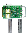
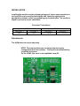
ACIM
USER’S MANUAL
A00296 Rev. K
This Manual covers revision G and H of the AC Isolation Module.
ACIM User’s Manual
A00296 Rev. K
Proprietary Data
This document contains confidential, proprietary
data with all rights and titles reserved by
GDI Communications LLC. By accepting this
document, the recipient assumes custody hereof
and agrees not to dislcose this data or any portion
of this data to any unauthorized person without
the prior written consent of GDI Communications
LLC. Recipient further agrees not to incorporate
these drawings, specifications or technical
information, in whole or in part, in any other
product or endeavor.
THIS LEGEND SHALL BE INCLUDED ON
ANY REPRODUCTION OF THIS DOCUMENT
GDI COMMUNICATIONS, LLC
879 Deming Way
Sparks, Nevada 89431
Phone: 775-345-8000
FAX: 775-345-8010
www.sgdi.com
Revision Location
TABLE of CONTENTS
GENERAL DESCRIPTION................................................................................................................................1
GENERAL CHARACTERISTICS.....................................................................................................................2
INSTALLATION .................................................................................................................................................3
ADJUSTMENTS ..................................................................................................................................................3
1 ACIM Users Guide A00296, Rev. K
GENERAL DESCRIPTION
The GDI Model ACIM AC Dual Isolation
Module consists of two functionally
identical input channels that detect
the presence or absence of AC on
their inputs and convert these
conditions to 170 compatible signals.
Each channel provides input
isolation, voltage hysteresis and
timing to qualify an input signal.
The output can be configured to be
CLOSED (252) when signal is present
on the input or OPEN (255) when the
signal is present.
FEATURES
Form factor consistent with the
standard input file.
Front panel mounted output
status indicators.
Front panel mounted test
switches.
Handle to facilitate insertion and
removal.
Lightning protection.
Input isolation.
Requires less than 1W per
channel from cabinet supply.
Power-up Output Clamp.
Prevents erroneous outputs on
power up.
ACIM Users Guide A00296, Rev. K
2
GENERAL CHARACTERISTICS
ACIM-252:
Output is ON when a signal greater Voltages passing through the
hysteresis band during a timing cycle
than 80 Volts ±3 Volts is applied
for a period of 110 ms ±15 ms.
will restart timing without affecting the
output state.
Output is OFF when a signal of less
than 70 Volts ±3 Volts is applied
The input has been designed to
for a period of 110 ms ±15 ms.
withstand the discharge of a 10microfarad capacitor charged to ±1000
Volts directly applied across the input
ACIM-255:
pins, with no load present on the
input pins.
Output is OFF when a signal
greater than 80 Volts ±3 Volts is
applied for a period of 110 ms ±15 The input has been designed to
withstand the discharge of a 10ms.
microfarad capacitor charged to ±2000
Output is ON when a signal of less Volts when connected across either
the input pins or from either side of
than 70 Volts ±3 Volts is applied
the input pins to equipment ground,
for a period of 110 ms ±15 ms.
with a dummy resistive load of 5
Ohms attached across the input pins.
ACIM-252/255 LA Version:
ENVIRONMENTAL
Output is ON (OFF for the 255)
when a signal greater than 83 Volts
Temperature -37 to +74o C
±3 Volts is applied for a period of
Humidity 95% non-condensing
150 ms ±50 ms.
Output is OFF (ON for the
255)when a signal of less than 67
Volts ±3 Volts is applied for a
period of 150 ms ±50 ms.
ACIM-252/255 NY Version:
The “NY” version of the module
incorporates a dipswitch, S3, which
is used to change the output
polarity.
INSTALLATION
Installing the module consists of simply plugging it into an unoccupied slot in
the Input File and connecting field signals and controller signals to the
appropriate positions on the corresponding rear terminal block. The module is
keyed to prevent incorrect installation.
Connector Terminations
INPUTS
CHANNEL 1
D and E
CHANNEL 2
J and K
OUTPUTS
CHANNEL 1
CHANNEL 2
F(+) and H(-)
W (+) and X(-)
Adjustments
The ACIM does not require adjusting.
NOTE: The output polarity can be changed by moving the
configuration zero ohm resistors. This must be accomplished by
a qualified technician.
On the 252NY, this can b e accomplished using S3.
GDI COMMUNICATIONS, L.L.C.
TRAFFIC EQUIPMENT MANUFACTURER ♦ SPECIALIZING IN COMMUNICATIONS
879 Deming Way
SPARKS, NEVADA 89431
TELEPHONE: 775-345-8000 FAX: 775-345-8010