1
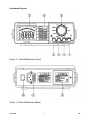
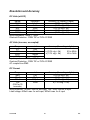
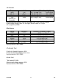
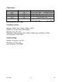
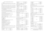
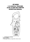
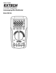
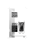
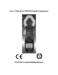
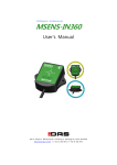
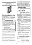
DVM645BI
BENCH MULTIMETER
TAFELMULTIMETER
MULTIMETRE DE TABLE
BANCO MULTÍMETRO
TISCHMULTIMETER
User Manual
Gebruikershandleiding
Manuel d'utilisation
Gebrauchsanleitung
DVM645BI – BENCH MULTIMETER
Introduction
This manual contains instructions and warnings that must be observed to ensure
safe operation and to keep the meter in a safe condition.
WARNING
READ "SAFETY INFORMATION"
BEFORE USING THE BENCH MULTIMETER
This multimeter is a portable 4000-count instrument that is designed for use in the
laboratory, the field, at home, and in other environments. This multimeter features
a compact design with rounded corners for easy handling, with a rugged shockresistant and fire-retardant case. It also has electronic overload protection for all
functions and ranges.
Unpacking and Inspection
Upon removing your new Bench Multimeter from its packaging, you should have
the following items:
1. Bench multimeter
2. Test lead set (one black, one red)
3. Carrying strap
4. Power lead
5. Instruction manual
If any of the above items are missing or are received in a damaged condition,
please contact the distributor from whom you purchased the unit.
Safety Precautions
Injury or death can occur even with low voltage and low current. It is extremely
important that you read this safety information before using your multimeter.
Follow all safety practices and proper operating procedures for the equipment
under test.
1. Exercise extreme caution when: measuring voltages above 20 volts,
measuring currents greater than 10mA, measuring AC power lines with
inductive loads, measuring AC power lines during electrical storms.
2. Always inspect your multimeter, test leads and accessories for signs of
damage or abnormality before every use. If there are any abnormalities
DVM645BI
1
GB
(i.e. broken or damaged test leads, cracked case, display not reading,
etc.) do not attempt to do any measurements.
3. Never earth yourself when making electrical measurements. Do not touch
exposed metal pipes, outlets, fixtures, etc., which might be at earth
potential. Keep your body insulated from earth by using dry clothing,
rubber shoes, rubber mats, or any approved insulating material.
4. Never touch exposed wiring, connections, test probe tips, or any live
circuit conductors when making measurements.
5. Never replace the protective fuse inside the multimeter with a fuse other
than the specified or approved type. Replace only with the same type of
fuse. To avoid electric shock, disconnect the test leads and any input
signals before replacing the fuse.
6. Replace only with the same type of battery. To avoid electric shock,
disconnect the power lead from the mains, and the test leads and any
input signal before replacing the battery.
7. Do not operate this multimeter in an explosive atmosphere (ie. in the
presence of inflammable gases or fumes, vapour or dust).
8. Measuring voltages that exceed the limits of the multimeter may damage
the meter and expose the operator to a shock hazard. Always respect the
meter voltage limits as stated on the front of the meter.
9. Never apply more than 500V DC between the COM connector and earth.
10. When testing for the presence of voltage or current, make sure the
voltage or current ranges are functioning correctly. Take a reading of a
known voltage or current before assuming a zero reading indicates no
current or voltage.
11. Do not attempt to calibrate or service the meter unless you are trained to
do so and another person capable of rendering first aid and resuscitation
is present.
12. Remember: Think Safety, Act Safely
Safety Information
The multimeter complies with Protection Class II, Overvoltage CAT II of IEC10101 (EN61010-1). Pollution degree 2 in accordance with IEC-664 indoor use. If the
equipment is used in a non-compliant manner, the protection provided by the
equipment may be insufficient.
This product complies with the requirements of the following European
Community Directives: 89/336/EEC (EMC) and 73/23/EEC (LVD) as amended by
93/68/EEC (CE marking).
DVM645BI
2
GB
Chapter 1
A quick tour
Explanation of Symbols
Attention ! Refer to the operating instructions
Dangerous voltage may be present at terminals
Ground (Earth Terminal)
AC - Alternating Current
DC - Direct Current
Audible Continuity
Equipment protected throughout by Double Insulation
(Protection Class II)
DVM645BI
3
GB
Instrument Layout
Figure 1-1. Bench Multimeter (Front)
Figure 1-2. Bench Multimeter (Back)
DVM645BI
4
GB
1. VΩ
Hz Volts, Ohms, Diode, and Frequency Input Terminal
Ω
This is the positive input terminal for all functions except current measurement.
The red test lead is connected to this.
2. COM
Common Terminal
This is the negative (ground) input terminal for all measurement modes. The
black test lead is connected to this.
3. mA
Milliamp Input Terminal
This is the positive input terminal for current measurements (AC or DC) up to
400mA. The red test lead is connected to this.
4. A
10 Amp Input Terminal
This is the positive input terminal for current measurements (AC or DC) up to
10A. The red test lead is connected to this.
5. Function / Range Selector Rotary Switch
This rotary switch selects the function, and selects the desired range.
6. Function / Range Selector Buttons
This button selects the function, and selects the desired range.
7. The LCD Display
The LCD display indicates the measured value of a signal, the function mode,
and indicators.
8. The Battery Cover
9. Power Supply Input with Fuse
WARNING
To avoid user injury and multimeter damage, the multimeter must be set to
the same AC voltage value as the mains before connecting the power lead
to the mains and switching on.
This switch is used to turn the AC Power on and off. When the AC Power is on,
the DC Power is automatically switched off.
10. The Power Switch
DVM645BI
5
GB
Using the Rotary Switch
Turn the multimeter on by turning the rotary switch to any function.
Using the Buttons
The buttons are push type switches. The functions are as follows:
BACK LIGHT Button
1.
button. When powered
You can turn the back light on or off by pressing the
by the battery, the back light will automatically switch off again after a short period
of time.
FUNCTION SELECTOR Button
2.
button switches
In the resistance and continuity range, each press of the
alternately between resistance and continuity.
button switches
In the frequency and adaptive test range, each press of the
alternately between frequency and adaptive test.
button switches alternately
In the DC and AC amps range, each press of the
between DC amps or AC amps.
button switches
In the DC and AC milliamps range, each press of the
alternately between DC milliamps or AC milliamps.
Data Hold: HOLD Button
3.
button to toggle in and out of the Data Hold mode, except if the
Press the
multimeter is already in the Min/Max Recording Hold mode.
When in the Data Hold mode, the " " indicator is displayed and the last reading is
held on the display, the beeper emits a tone.
button when the multimeter is in the Data Hold mode will cause
Pressing the
it to exit Data Hold and enter the Min/Max Recording Hold mode.
button to stop recording the
In the Min/Max Recording Hold mode, press the
readings, press
again to resume recording.
However, the multimeter is still operating in Data Hold mode, therefore, the buzzer
will still sound if the over range or continuity mode occurs. And the range will also
change if it is in auto range.
Delay Data Hold: DELAY HOLD Button
4.
button to toggle in and out of the Data Hold mode, and the " "
Press the
indicator turns on or off.
DVM645BI
6
GB
5.
Min/Max Recording Hold: MIN/MAX Button
button to enter the Min/Max Recording Hold mode. The minimum
Press the
and maximum values are then reset to the current input, the readings are stored in
memory, and the " " indicator turns on. Push the button to cycle through the
minimum (MIN), maximum (MAX), and current readings. The "MIN" or "MAX"
indicator turns on to indicate what value is being displayed.
button to stop recording the
In the Min/Max Recording Hold mode, press the
readings, press again to restart recording. If recording is stopped, the minimum,
maximum, or current values and the analogue display are frozen. In the Min/Max
Recording Hold mode, if a new minimum value exceeds the actual minimum
readings, or a new maximum value is an overload value, the minimum or
maximum value will be held on the display, but the analogue display will continue
to be active.
If in auto range, the mode is held just before the range.
Relative Display: REL Button
6.
button to enter the Relative Display mode, the "REL" indicator turns
Press the
on, the displayed reading is stored as a reference value, and the display is then
set to zero.
In the Relative Display mode, the value shown on the LCD is always the
difference between the stored reference value and the current reading. If the new
reading is the same as the reference value, the display will indicate zero.
The bar graph displays absolute value, not relative value. And the over range also
occurs according to the absolute value.
With auto-range, the range is held just before range.
button for more than one second to exit the relative
Press and hold down the
mode.
RANGE Button
7.
button to select the Manual Range mode and turn off the "AUTO"
Press the
indicator.
button is pressed, the range (and
In the Manual Range mode, each time the
the input range indicator) increments and a new value is displayed.
To exit the Manual Range mode and return to auto range, press and hold down
button for more than one second. The "AUTO" indicator turns back on.
the
The DC V, AC V, resistance and capacitance measurements are always first set
to the auto range by default.
The frequency measurement is always set to the auto range.
The continuity, diode, ADP, DC A and AC A measurements are always set to the
manual range.
When the power is turned on, the default range is selected.
DVM645BI
7
GB
8.
Data Memory: MEM STO Button
button to enter the Data Memory mode and turn on the "MEM"
Press the
indicator. All the display data is then stored in the memory. The stored data can
be read out and displayed on the LCD, which then switches to the Data Recall
Hold mode.
Data Recall Hold: MEM RCL Button
9.
button to enter the Data Recall mode and turn on the "MEM" and
Press the
" " indicator. The stored data can be read out and displayed on the LCD, which
then switches to the Data Recall Hold mode.
While storing data in the memory display, the "MEM" indicator flashes. The Data
button or the
button.
Recall Hold mode is exited by pressing the
Buzzer Output
A 2kHz buzzer sounds in the following cases:
1. When the key is operated.
2. When the over-range occurs, except for resistance (Ω
Ω), frequency (Hz),
continuity (
) and diode (
) measurements.
3. When the continuity measurement results in less than 40Ω.
4. When the relative mode is exited.
5. When the mode is changed from manual to auto range by operating the
button. Please refer to the timing chart for the timing.
Low Battery Indication
" indicator is displayed when the battery voltage falls below the reliable
The "
operating level.
DVM645BI
8
GB
Chapter 2
Measurements
Introduction
WARNING
To avoid user injury and multimeter damage, the
multimeter must be set to the correct value of mains
voltage before connecting the power lead to the mains and
switching on.
Before doing any measurements always examine the multimeter and accessories
for any damage, contamination (excessive dirt, grease, etc.) and defects. Examine
the test leads for cracked or frayed insulation and make sure the lead plugs fit
snugly into the multimeter sockets. If there are any abnormalities, do not attempt
to do any measurements.
DVM645BI
9
GB
Measuring DC Volts
Circuit
Red
Figure 2-1. Measuring DC Volts
WARNING
To avoid possible electric shock, multimeter damage and/or
equipment damage, do not attempt to do any voltage measurements if
the voltage is above 1000V DC / 750V AC RMS. 1000V DC / 750V AC
RMS are the maximum voltages that this multimeter is designed to
measure.
c Turn the Selector to Volts DC
d Connect the leads as shown
e
is not available in Volts DC, all other buttons can be used.
1. Insert the black and red test leads into the COM and VΩ
Ω
Hz input terminals
respectively.
2. Select the desired DC voltage range, or set to auto range.
3. When the magnitude of the voltage to be measured is unknown, always start
with the highest range.
4. Connect the test leads in parallel with the circuit to be measured. Be careful
not to touch any live conductors with your hands. Note the reading.
5. For DC voltage readings, the red lead should be connected to the positive side
of the circuit, the black lead to the negative side. A minus sign on the left-hand
side of the LCD will appear if the leads are connected the other way around.
6. When all measurements have been completed, disconnect the test leads from
the circuit under test. Remove the test leads from the multimeter.
DVM645BI
10
GB
Measuring AC Volts
Circuit
Red
Figure 2-2. Measuring AC Volts
WARNING
To avoid possible electric shock, multimeter damage and/or
equipment damage, do not attempt to do any voltage measurements if
the voltage is above 1000V DC / 750V AC RMS. 1000V DC / 750V AC
RMS are the maximum voltages that this multimeter is designed to
measure.
c Turn the Selector to Volts AC
d Connect the leads as shown
e
is not available in Volts AC, all other buttons can be used.
1. Insert the black and red test leads into the COM and VΩ
Ω
Hz input terminals
respectively.
2. Select the desired AC voltage range, or set to auto range.
3. When the magnitude of the voltage to be measured is unknown, always start
with the highest range.
4. Connect the test leads in parallel with the circuit to be measured. Be careful
not to touch any live conductors with your hands. Note the reading.
5. When all measurements have been completed, disconnect the test leads from
the circuit under test. Remove the test leads from the multimeter.
DVM645BI
11
GB
Measuring DC and AC Amps
Circuit
Red
Figure 2-3. Measuring Amps
WARNING
Do not attempt to measure high currents. Use a current clamp for
measurements >10A. The 10A input terminal is protected by a
F15A/250V fast blow ceramic fuse.
c Turn the selector to DC and AC Amps.
d Connect the leads as shown
e
is not available in DC and AC Amps, all other buttons can be used.
Each press of the button
switches alternately between DC and AC Amps.
1. Insert the black and red test leads into the COM and A input terminals
respectively.
2. Turn off or disconnect the circuit to be measured from all power sources,
connect the multimeter in series with the conductor where the current is to be
measured.
3. Switch on the power to the circuit under test. Note the reading.
4. After completing the measurement, turn off the power to the circuit under test,
disconnect the test leads from the multimeter.
5. The DC and AC Amps measurements are always fixed range.
DVM645BI
12
GB
Measuring DC and AC Milliamps
Circuit
Red
Figure 2-4. Measuring Milliamps
WARNING
Do not attempt to measure high currents. The mA input terminal is
protected by a F1A/250V fast blow ceramic fuse.
c Turn the selector to DC and AC Milliamps.
d Connect the leads as shown.
is not available in DC and AC Milliamps, all other buttons can be used.
e
Each press of the button
switches alternately between DC or AC Milliamps.
1. Insert the black and red test leads into the COM and mA input terminals
respectively.
2. Select the desired DC current range or AC current range.
3. Turn off or disconnect the circuit to be measured from all power sources,
connect the multimeter in series with the conductor where the current is to be
measured.
4. Switch on the power to the circuit under test. Note the reading.
5. After completing the measurement, turn off the power to the circuit under test,
disconnect the test leads from the multimeter.
6. The DC and AC Milliamps measurements are always fixed range.
DVM645BI
13
GB
Measuring Frequency and Adaptive Measurement
Circuit
Red
Figure 2-5. Measuring Frequency and Adaptive Measurement (ADP)
c Turn the selector to frequency and adaptive measurement.
d Connect the leads as shown
is not available in frequency and adaptive measurement, all other buttons
e
can be used.
Each press the button
measurement.
switches alternately between frequency and adaptive
Hz input terminals
1. Insert the black and red test leads into the COM and VΩ
Ω
respectively.
2. In the frequency test, it is not necessary to know the range, as the multimeter
will automatically range up or down to display the best resolution. Manual range is
not available.
3. Ensure that the amplitude level of the signal to be measured is not greater
than the input voltage limit (250V DC/AC rms). The signal amplitude must also be
greater than the sensitivity level.
4. Attach the probe tips to the points across which the frequency is to be
measured, and read the result directly from the display.
5. The frequency range is always set to auto range.
The Adaptive (ADP) Measurement is as follows:
Hz input
1. Connect the ADP signal terminal (-) and (+) to the COM and VΩ
Ω
terminals respectively.
2. The ADP voltage is supplied to the multimeter directly. The result is displayed
on a scale of 10 units per 1mV.
3. The ADP measurement is always fixed range. The full range is 400mV DC.
DVM645BI
14
GB
Measuring Capacitance
Red
Figure 2-6. Measuring Capacitance
WARNING
Turn off the power to the device under test and discharge all
capacitors.
c Turn the selector to capacitance.
d Connect the leads as shown: insert the black and red test leads into the COM
Hz input terminals respectively.
and VΩ
Ω
is not available with capacitance, all other buttons can be used.
e
1. Turn off the power to the device under test and discharge all capacitors.
2. Completely discharge the capacitor before measuring its capacitance value.
3. Set to the capacitance range that gives the most accurate reading or select
auto range.
4. Connect the crocodile clips to the capacitor leads or insert the capacitor leads
into the multimeter measuring socket. Always observe the correct polarity when
measuring electrolytic capacitors.
5. Read the capacitance value directly from the display. The accuracy of the
button
capacitance measurement can be improved by first pressing the
(Relative mode) in order to zero the display and automatically subtract the
residual multimeter and test lead capacitance. The Relative mode also selects
manual range.
6. Residual charge in the capacitor, or capacitors with poor insulation resistance
or poor dielectric absorption may cause measurement errors.
NOTE: A safe way to discharge a capacitor is to connect a 100kΩ resistor across
the two capacitor leads.
DVM645BI
15
GB
Testing Diodes
Red
Figure 2-7. Diode Test
WARNING
Measurements must always be done with the circuit power OFF.
c Turn the selector to Diode.
d Connect the leads as shown: insert the black and red test leads into the COM
Hz input terminals respectively.
and VΩ
Ω
and
are not available in diode test, all other buttons can be used.
e
) position by turning the rotary switch.
1. Select the (
2. Insert the black and red test leads into the COM and VΩ
Ω
Hz input terminals
respectively.
3. The red lead should be connected to the anode and the black lead to the
cathode of the diode.
4. The typical voltage drop should be about 0.6V for a silicon diode or 0.3V for a
germanium diode.
5. If the diode is reverse biased or there is an open circuit and the reading will be
between 3.000V and 3.400V.
6. The Diode test is always fixed range.
DVM645BI
16
GB
Measuring Resistance and Continuity
Red
Figure 2-8. Measuring Resistance and Continuity
c Turn the selector to Resistance and Continuity measurement.
d Connect the leads as shown.
is not available in continuity test, all other buttons can be used.
e
Each press of the button
continuity measurement.
switches alternately between resistance and
Resistance measurement is as follows:
button.
1. Select resistance by pressing the
Ω
Hz input terminals
2. Insert the black and red test leads into the COM and VΩ
respectively.
3. Select the desired ohms (Ω) range or set to auto range. Connect the black and
red test probes to the circuit or device under test. First make sure that the circuit
or device is dead.
4. Turn off any power to the resistor to be measured. Discharge any capacitors.
Any voltage present during a resistance measurement will cause inaccurate
readings and could damage the meter if the overload protection of 250V DC or AC
rms is exceeded.
5. Open circuits will be displayed as an overload condition and the MSD (Most
Significant Digit) will blink.
DVM645BI
17
GB
6. The resistance of the test leads can diminish accuracy in the lowest (400Ω)
range. The error is usually 0.1 to 0.2Ω for a standard pair of test leads. To
determine the error, short the test leads together and the use the
Relative
mode to automatically subtract the lead resistance from the resistance
measurement.
7. After all measurements have been completed, disconnect the test leads from
the circuit and multimeter input terminals.
The Continuity (
) measurement is as follows:
button.
1. Select the continuity measurement by pressing the
Hz input terminals
2. Insert the black and red test leads into the COM and VΩ
Ω
respectively.
3. Connect the black and red test probes to the circuit or device under test. First
make sure that the circuit or device is dead.
4. An audible tone will sound when the resistance is less than approximately
40Ω.
5. After the continuity measurement has been completed, disconnect the test
leads from the circuit and multimeter input terminals.
6. The continuity measurement is always fixed range. Open circuit voltage is
approximately 0.45V.
DVM645BI
18
GB
Chapter 4
Specifications
General Specifications
Maximum voltage between terminals and earth: CAT. II 1000V DC or 750V AC
rms (sine)
Display: 3 3/4 digit (4000 count) digital indication. Frequency range: 9999 counts
max.
42 segment analogue bar graph
Full indicators, automatic polarity indication
Measuring rate:
Digital 2 times per second
Analogue bar graph 20 times per second
Capacitance 1 time per second
Over range indications: MSD (Most Significant Digit) blinks
Low Battery indication:
The "
" indicator is displayed when the battery
voltage drops below the reliable operating level.
Temperature coefficient: 0.15 x specified accuracy per °C
< 18°C to >28°C
Temperature: Operating: 5°C to 35°C
Storage: -10°C to 60°C
Relative humidity: 20% to 75% RH (5°C to 35°C)
Back light
Safety:
Power requirements
Size
Weight
Accuracy is given as ± (% of reading + number of least significant digit) at 18°C to
28°C, with relative humidity up to 75%.
All specifications assume less than 1 year since calibration.
DVM645BI
19
GB
Resolution and Accuracy
DC Volts (mV DC)
Range
resolution
Accuracy (% reading + digits)
400mV
0.1mV
± (0.3% rdg + 5d)
4V
1mV
± (0.3% rdg + 2d)
40V
10mV
± (0.3% rdg + 2d)
400V
100mV
± (0.3% rdg + 2d)
1000V
1V
± (0.3% rdg + 2d)
Input impedance: 10MΩ, < 100pF
Overload Protection: 1000V DC or 750V AC RMS
AC Volts (true rms, ac-coupled)
Range
resolution
Accuracy (% reading + digits)
4V
1mV
± (0.8% rdg + 5d)
50 to 60Hz
40V
10mV
± (1.2% rdg + 5d)
45 to 1kHz
400V
100mV
750V
1V
Input impedance: 10MΩ, < 100pF
Overload Protection: 1000V DC or 750V AC RMS
AC coupled true RMS
DC Current
Range
resolution
Accuracy (% reading + digits)
4mA
1µA
± (0.8% rdg + 5d)
40mA
10µA
± (0.8% rdg + 5d)
400mA
100µA
± (0.8% rdg + 5d)
10A
10mA
± (1.5% rdg + 10d)
(20A for 30
seconds)
Input protection: 1A/250V fuse for mA input, 15A / 250V fuse for A input
Load voltage: 600mV max. for mA input, 900mV max. for A input
DVM645BI
20
GB
AC Current
Range
resolution
Accuracy (% reading + digits)
4mA
1µA
± (1.5% rdg + 5d)
45 to 400Hz
40mA
10µA
± (1.5% rdg + 5d)
45 to 400Hz
400mA
100µA
± (1.5% rdg + 5d)
45 to 400Hz
10A
10mA
± (2% rdg + 10d)
45 to 400Hz
(20A for 30
seconds)
Input protection: 1A/250V fuse for mA input, 15A / 250V fuse for A input
Load voltage: 600mV max. for mA input, 900mV max. for A input
AC coupled true RMS
Resistance
Range
resolution
400Ω
0.1Ω
4kΩ
1Ω
40kΩ
10Ω
400kΩ
100Ω
4MΩ
1kΩ
40MΩ
10kΩ
Open circuit Voltage: 0.45V
Input protection: 250V RMS
Accuracy (% reading + digits)
± (0.5% rdg + 5d)
± (0.5% rdg + 3d)
± (0.5% rdg + 3d)
± (0.5% rdg + 3d)
± (1% rdg + 5d)
± (1.5% rdg + 10d)
Continuity Test
Continuity threshold: approx. 40Ω
Continuity threshold: 2kHz buzzer tone
Input protection: 250V RMS
Diode Test
Test current: 0.6mA
Open circuit voltage: approx. 3.0V
Input protection: 250V RMS
DVM645BI
21
GB
Capacitance
Range
4nF
40nF
400nF
4µF
40µF
resolution
1pF
10pF
100pF
1nF
10nF
Accuracy (% reading + digits)
± (2% rdg + 40d)
in relative mode
± (2% rdg + 5d)
in relative mode
± (2% rdg + 5d)
in relative mode
± (0.5% rdg + 5d)
± (2% rdg + 5d)
at <= 20µF
± (5% rdg + 5d)
at > 20µF
Input protection: 250V RMS
Frequency Counter
Ranges: 100Hz, 1kHz, 10kHz, 100kHz, 1MHz
Resolution: 0.01Hz in the 100Hz range
Accuracy: ± (0.1% + 4d)
Sensitivity: 100mV rms for 1Hz to 20kHz, 500mV rms for 20kHz to 1MHz
Input protection: 250V RMS
Adaptive Range
Display: 10 units per 1mV DC
Accuracy: ± (0.3% + 5d)
Input protection: 250V RMS
DVM645BI
22
GB
Chapter 4
Maintenance
Introduction
Any repairs or servicing not covered by this manual should only be done by
qualified personnel.
Battery Replacement
WARNING
To avoid electric shock, disconnect the power leads from the mains,
and disconnect the test leads and any input signals before replacing
the battery. Only replace with same type of battery.
" indicator, the battery must be replaced to
When the multimeter displays the "
maintain proper operation. Use the following procedure to replace the battery:
1.
Disconnect the test leads from any live source, turn the rotary switch to off,
and remove the test leads from the input terminals.
2.
Remove the screws on the battery cover and open it.
3.
Remove the dead battery and replace with a new equivalent 9V battery.
4.
Two types of battery are used in the bench multimeter: one is a NEDA
1604 6F22 006P type x 1 or equivalent 9V battery, the other is IEC LR6
AM3 AA 1.5V x 6.
5.
Never use the bench multimeter unless the battery cover is in place and
properly fastened.
DVM645BI
23
GB
Fuse Replacement
WARNING
To avoid electric shock, disconnect the test leads and any input
signals before replacing the fuses. Replace only with the same type of
fuse. The A input terminal is protected by a F 15A/250V fast blow
ceramic fuse. The mA input terminal is protected by a F 1A/250V fast
blow ceramic fuse.
Use the following procedure to examine or replace the multimeter fuses:
1.
Turn the power switch to off, and disconnect the power cable from the
mains.
2.
Disconnect the test leads from any live source, turn the rotary switch to off,
and remove the test leads from the input terminals.
3.
Open the tools cover on the top, and open the fuse cover in the tool case.
4.
Remove the blown fuse, replace with a fuse of the same size and rating.
Make sure the new fuse is centred in the fuse holder.
5.
Replace the blown fuse with one of the same rating.
6.
The A input terminal is protected by a F 15A/250V fast blow ceramic fuse,
Ø 6 x 30mm. The mA input terminal is protected by a F 1A/250V fast blow
ceramic fuse, Ø 5 x 20mm.
7.
Fuses rarely need replacement and almost always blow as a result of
operator error.
8.
Never use the bench multimeter unless the fuse cover is in place and fully
fastened.
Power Fuse Replacement
WARNING
To avoid electric shock, disconnect the power cable from the mains,
and disconnect the test leads and any input signals before replacing
the power fuse. Only replace with same type of fuse
Use the following procedure to examine or replace the power fuse:
1.
Turn the power switch to off, and disconnect the power cable from mains.
2.
Disconnect the test leads from any live source, turn the rotary switch to off,
and remove the test leads from the input terminals.
3.
Replace the power fuse in the power supply input. Replace the blown fuse
with one of the same rating.
4.
The power fuse is 80mA/250V, Fast, Ø 5 x 20mm
DVM645BI
24
GB
Other notes
1.
2.
Do not use abrasives or solvents on the bench multimeter, use a damp
cloth with mild detergent only.
If any faults or abnormalities are observed, the bench instrument should
not be used and needs to be inspected.
DVM645BI
25
GB