1
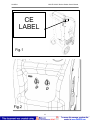
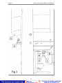
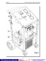
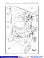
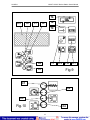
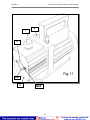
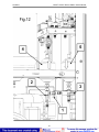
LAUNCH VALUE-100 A/C Service Station User’s Manual INDEX INTRODUCTION .........................................................................................................................................1 CARE OF THE MANUAL .......................................................................................................................1 WARRANTY ................................................................................................................................................1 GENERAL INFORMATION .........................................................................................................................2 END-OF-LIFE ..............................................................................................................................................2 SAFETY RULES ..........................................................................................................................................2 PRECAUTIONS FOR HANDLING AND USE OF REFRIGERANT FLUIDS .........................................3 PRINCIPLES OF OPERATION ...................................................................................................................3 SETUP.........................................................................................................................................................3 THE MACHINE ............................................................................................................................................4 BASIC COMPONENTS ..........................................................................................................................4 CONTROLS AND CONTROL SYSTEM ................................................................................................4 FUNCTION SELECTOR KEYBOARD ...................................................................................................4 STATUS AND ALARM PANEL ...............................................................................................................5 PRELIMINARY OPERATIONS....................................................................................................................5 PURGE NON CONDENSABLE GAS .....................................................................................................6 RECOVERY/RECYCLING PHASE ........................................................................................................6 VACUUM PHASE ...................................................................................................................................7 CHARGING/REINTEGRATION PHASE ................................................................................................7 ROUTINE MAINTENANCE .........................................................................................................................8 FILLING THE MACHINE BOTTLE .........................................................................................................8 VACUUM PUMP .....................................................................................................................................9 M.1) Oil top-up ................................................................................................................................9 M.2) Oil change...............................................................................................................................9 REPLACING THE DRYER FILTERS .....................................................................................................9 FILLING THE NEW OIL TANK .............................................................................................................10 EMPTYING THE USED OIL TANK ......................................................................................................10 SPECIAL MAINTENANCE OPERATIONS ...............................................................................................10 CALIBRATING THE ELECTRONIC SCALE ........................................................................................10 ADDITIONAL SETTINGS ..........................................................................................................................11 CHANGING THE UNITS OF MEASURE (kg lbs or lbskg).............................................................11 PRINTER (OPTIONAL) .............................................................................................................................11 LEGEND ...............................................................................................................................................11 REPLACING THE PRINTER PAPER ..................................................................................................11 i LAUNCH VALUE-100 A/C Service Station User’s Manual INTRODUCTION This manual was drafted in accordance with the EEC Guidelines contained in Directive no. 392/89 as amended. This manual contains important information pertinent to operator safety. Read this manual through at least once before operating the machine. The manufacturer reserves the right to modify this manual and the machine itself with no prior notice. We therefore recommend checking any updates. This manual must accompany the machine in case of sale or other transfer. CARE OF THE MANUAL This manual must be kept in a cool, dry place and must be kept for the entire life of the machine. Take care not to damage this manual in whole or in part during consultation. Do not remove pages from this manual. Do not write on the pages; space for notes is provided at the end of each chapter. WARRANTY This product is warranted against any defect in materials and/or construction for a period of 1 (one) year from the date of delivery. The warranty consists of free -of-charge replacement or repair of defective component parts or parts considered defective by the Manufacturer. Reference to the machine serial number must be included in any requests for spare parts. Parts not covered by the manufacturer warranty are: pressure gauges. This warranty does not cover defects arising from normal wear, inco rrect or improper installation, or phenomena not inherent to normal use and operation of the product. Manufacturer guarantees the perfect suitability of the materials used for packing, in terms both of composition and mechanical strength/resistance. The gu arantee does not cover breakdowns attributable to damage suffered during shipping or warehousing or caused by the use of accessories not meeting manufacturer’s specifications, or to tampering with or repair of the product by unauthorized personnel. It is o f utmost importance that the crates containing the machine be carefully inspected, upon delivery, in the presence of the shipping agent. We recommend performing inspection with extreme care, since damages to the crates due to shocks or dropping are not always immediately visible thanks to the shock -absorbing capacity of today’s composite packing materials. The apparent integrity of the packing materials does not exclude possible damage to the goods, despite the due care taken by the manufacturer in packing them. NOTE: Regarding the above, the Manufacturer reminds the Customer that according to international and national laws and regulations in force the goods are shipped at the sole risk of the latter and, unless otherwise specified in the confirmation of or der phase, the goods are shipped uninsured. The Manufacturer therefore declines any and all responsibility in merit of REQUESTS for damages due to shipping, loading and unloading, and unpacking. The product for which repair under guarantee is requested mus t be shipped to the manufacturer under the customer’s exclusive responsibility and at the customer’s exclusive expense and risk. In order to avoid damage during shipping for repairs, the Manufacturer’s original packing must always be used. The manufacturer declines any and all responsibility for damage to vehicles on which recovery/recycling and recharging are performed if said damage is the result of unskillful handling by the operator or of failure to observe the basic safety rules set forth in the 1 LAUNCH VALUE-100 A/C Service Station User’s Manual instruction manual. This warranty replaces and excludes any other warranty or guarantee that the seller is required to provide under law or contract and defines all the customer’s rights in regard of faults and defects and/or scarce quality in the products as pu rchased. Failure to observe the aforementioned conditions shall invalidate all forms of warranty on the MACHINE. GENERAL INFORMATION Machine identification information is printed on the data plate on the rear of the machine (Fig.1). Overall machine dimensions: Height: 1060 mm Width: 500 mm Depth: 520 mm Weight: 80 Kg Like any equipment with moving parts, the machine inevitably produces noise. The construction system, paneling, and special provisions adopted by the Manufacturer are such that during work the average noise level of the machine is not in excess of 7 0 dB (A). END-OF-LIFE The symbol on the right indicates that in accordance with Directive 2002/96/EC the machine may not be disposed of as ordinary municipal waste but must be delivered to a specialized center for separation and disposal of WEEE (Waste Electrical and Electronic Equipment) or be returned to the dealer in case of purchase of a new machine. Current legislation provides severe sanctions in the case of disposal of WEEE into the environment. If improperly used or disposed of into the environment, electrical and electronic equipment can release substances dangerous for the environment and for human health. SAFETY RULES The machine designed for use in recovering the R134a refrigerant fluid used in the air conditioning (A/C) systems of motor vehicles. The machine is designed to be used by qualified personnel only; moreover, correct use of the machine will depend on the operator’s knowledge of the information contained in this manual, including the basic safety rules set forth below: Wear protective gloves and goggles. Do not expose the machine to direct sunlight or rain. Use only in well-ventilated work areas. Before performing any operation, check the vehicle use and maintenance manual for the type of refrigerant fluid used by the A/C system. Do not smoke in proximity to the machine while it is in operation. Do not use the machine in proximity to sources of heat, open flames, or sparks. Check whenever the engine is turned off that the ignition key is turned to the full OFF position. Always close all the valves on the machine before connecting it to the A/C system of the vehicle. Connect only the machine hose supplied with the RED quick -connect coupling to the high-pressure branch of the A/C system. Connect only the machine hose supplied with the BLUE quick-connect coupling to the low-pressure branch of the A/C system. Keep the connection hoses away from moving parts and rotating elements such as cooling fans, alternators, etc. Keep the connection hoses away from hot objects and elements such as engine exhaust pipes, radiators, etc. Fill the A/C system with the quantity of refrigerant recommended by the manufacturer. Never exceed said quantity. Check the oil levels at the beginning of each operation. Always top up with the correct quantity of oil. Before connecting 2 LAUNCH VALUE-100 A/C Service Station User’s Manual the MACHINE, check that voltage and frequency of main electrical supply match the value shown into the CE label. Never fill the bottle to more than 80% of maximum capacity in order to leave an expansion chamber for absorbing any pressure increases. Never touch the valves on the refrigerant bottle installed on -board the MACHINE. Dispose of the oil extracted from the A/C system and from the vacuum pump in suitable containers for used oils. Replace the filters punctually at the prescribed replacement times. Use only filters recommended by the manufacturer. Use only the oils recomm ended by the manufacturer. Take care never to use the vacuum pump oil in the A/C system, or vice -versa. Failure to observe any of the above safety precautions will invalidate all forms of guarantee on the MACHINE. PRECAUTIONS FOR HANDLING AND USE OF REFRIG ERANT FLUIDS Refrigerant fluids expand to the gaseous state in standard environmental conditions. In order that they may be shipped and used they must be compressed into suitable bottles. We therefore recommend observing all the general precautions applica ble to handling of pressurized containers. In the case of R134a in particular, we suggest the following special precautions: Avoid inhaling highly concentrated vapors even for short periods of time, since such vapors can cause loss of consciousness or deat h. R134a is not flammable, but if the vapor is exposed to open flames or incandescent surfaces it may undergo thermal decomposition and form acid substances. The acrid and pungent odor of these products of decomposition is sufficient to signal their presen ce. We therefore recommend avoiding use of R134a near open flames and incandescent elements. There exists no evidence of risks deriving from transdermal absorption of R134a. Nevertheless, due to the low boiling point of the liquid, it is advisable to wear protective garments such as to ensure that no jets of liquid or gas can come into contact with the skin. The use of goggles to avoid contact with the eyes is especially recommended, since the refrigerant liquid or gas can cause freezing of the ocular fluids. Moreover, we strongly advise users to avoid dispersing the R134a refrigerant fluid utilized in the machine since it is a substance that contributes to raising the temperature of the planet, with a global warming potential(GWP) of 1300. PRINCIPLES OF OPERATION In a single series of operations, the machine permits recovering and recycling refrigerant fluids with no risk of releasing the fluids into the environment, and also permits purging the A/C system of humidity and deposits contained in the oil. The machine is equipped with a built-in evaporator/separator that removes oil and other impurities from the refrigerant fluid recovered from the A/C system and collects them in a container for that purpose. The fluid is then filtered and returned perfectly recycled to the bottle installed on the MACHINE.. The machine also permits running certain operational and seal tests on the A/C system. SETUP The machine is supplied fully assembled and tested. Referring to Figure 2, mount the hose with the BLUE quick-connect coupling on the male threaded connector indicated by the BLUE LOW PRESSURE symbol and the hose with the RED quick -connect coupling on the male threaded connector indicated by the RED HIGH PRESSURE symbol. Referring to Figure 3, remove the protection under the refrigerant scale as follows: - Loosen the nut [2]. 3 LAUNCH - VALUE-100 A/C Service Station User’s Manual Completely loosen the screw [1]. Keep the screw [1], the nut [2], and the knurled washer [4] for possible future use. NOTE: in the event that the equipment has to be transported, the refrigerant bottl e scale should be locked in place as follows: - Procure two size 10 wrenches. - Tighten the nut [2] almost completely onto the screw [1]. - Insert the knurled washer [4] onto the screw [1]. - Turn the screw [1] just a few times on the threaded bush [6]. - Switch the machine on. - Tighten the screw [1] until the display signals ZERO availability. - Tighten the nut [2] forcefully (using the second wrench to block the screw [1]). - Check that the screw [1] is actually locked, if necessary repeat the locking operation from the beginning. THE MACHINE BASIC COMPONENTS Refer to fig 4,5,6,7: a) Control console b)Taps c) Handle d) High/Low Pressure threaded connectors e) Top-up oil container f) Bottle g) Drying filters h)Electronic scale i) Heating resistance j) Main switch k) Socket for electrical supply plug l) Fuse m) Used oil container n) Serial port o) Humidity gauge p) Vacuum pump q) Wheels CONTROLS AND CONTROL SYSTEM Refer to fig 8: (A1) High pressure gauge for A/C system (A2) Low pressure gauge for A/C system (A3) Printer (optional) (A4) Pressure gauge for bottle refrigerant pressure (A6) Emergency/alarms panel (A7) Display (A8) Pushbuttons for modifying and starting/stopping operations (A9) Operations selector panel FUNCTION SELECTOR KEYBOARD Refer to fig 9: 4 LAUNCH VALUE-100 A/C Service Station User’s Manual (T1) Availability LED indicator: when lit, the display reports the quantity of refrigerant fluid contained in the bottle. (T2) Charging LED indicator (flashes during the CHARGING phase). (T3) Recovery LED indicator (flashes during the RECOVERY p hase). (T4) Vacuum LED indicator (flashes during the VACUUM phase). (T5) Oil Discharge indicator (flashes during the OIL DISCHARGE phase). (T6) SEL key: Selects the operation to be performed. Every time this key is pressed one of the LEDs from T1 through T4 will light in sequence; the LED alongside each operation indicates that the operation may be started or that it is being performed (flashing LED). (T7) + key: Each time this key is pressed during the operations relative to setting the time and the quantity, the value of the flashing digit on the display will be increased by one unit. (T8) ARROW key: Each time this key is pressed while a display value is flashing during the operations relative to setting the time and the quantity, a different digit will be selected for modification (selected digit will flash). (T9) ENTER key: Pressing this key when a LED corresponding to an operation is lit but not flashing will permit modifying the times and the fluid quantities. Upon completion of modification, press the key again to confirm the datum (T10) START key: Pressing this key will start the operation indicated by the lighted LED (T11) STOP key: Pressing this key will stop the operation indicated by the flashing LED. (T12) TEMPERATURE key: Pressing this key th e display will show the bottle temperature in Celsius degree and Fahrenheit degree. (T13) Display: According to the operation selected, displays the time or refrigerant quantity values. STATUS AND ALARM PANEL See fig 10: (C1) HEATER ON: Lights to indicate that the electrical resistance of the machine is heating the bottle to maintain fluid pressure between 5.5 and 8,5 bar. The resistance does not operate during the RECOVERY phase of operation (C2) HIGH PRESSURE: Lights and emits an acoustic signal when the pressure of the fluid in the circuit catch up 17.5 bar. The RECOVERY operation is automatically interrupted. (C3) FULL BOTTLE: Lights and emits an acoustic signal when the bottle is full to more than 80% capacity (that is, 10 kg). The Recovery operation is automatically interrupted. (C4) EMPTY BOTTLE: Lights and emits an acoustic signal when the quantity of refrigerant fluid contained in the bottle is low (2 kg). in order to avoid the emission of non -condensable gases. Fill the bottle according to the proce dure described in the ROUTINE MAINTENANCE section. PRELIMINARY OPERATIONS Check that switch (j) is set to position 0. Check that all the machine taps are closed. Connect the machine to the electrical supply and switch on. Check that the vacuum pump oil lev el 5 LAUNCH VALUE-100 A/C Service Station User’s Manual indicator shows at least one-half full. If the level is lower, add oil as explained in the MAINTENANCE section. Check that in the top -up oil container (e) there are at least 100 cc of the oil recommended by the manufacturer of the vehicle A/C system. Ch eck the level of the oil in container (m) (< 200 cc). Check on the machine display that there are at least 3 kg of refrigerant in the bottle. Should this not be the case, fill the machine bottle from an external bottle of appropriate refrigerant following the procedure described in the ROUTINE MAINTENANCE section. PURGE NON CONDENSABLE GAS Before every service, check if there is air into the bottle; press the temperature bottle key (ref .12 fig.9) and read the temperature of the bottle. Compare the bottle p ressure with the one into the table; if the bottle pressure if higher of the pressure read on the table, pull the ring of the security valve and bring back the bottle pressure to the table values. Example: Bottle temperature = 20 °C, the bottle pressure mu st bring back at 5,2 bar. T P T P T P T P T P T P T P T P T P (°C) (bar) (°C) (bar) (°C) (bar) (°C) (bar) (°C) (bar) (°C) (bar) (°C) (bar) (°C) (bar) (°C) (bar) 10 3,6 15 4,4 20 5,2 25 6,1 30 7,2 35 8,3 40 9,6 45 11 50 12,6 10,5 3,7 15,5 4,4 20,5 5,3 25,5 6,2 30,5 7,3 35,5 8,4 40,5 9,7 45,5 11,2 50,5 12,8 11 3,8 16 4,5 21 5,4 26 6,3 31 7,4 36 8,6 41 9,9 46 11,3 51 12,9 11,5 3,8 16,5 4,6 21,5 5,5 26,5 6,4 31,5 7,5 36,5 8,7 41,5 10 46,5 11,5 51,5 13,1 12 3,9 17 4,7 22 5,6 27 6,5 32 7,6 37 8,8 42 10,2 47 11,6 52 13,3 12,5 4 17,5 4,8 22,5 5,6 27,5 6,6 32,5 7,7 37,5 8,9 42,5 10,3 47,5 11,8 52,5 13,4 13 4,1 18 4,9 23 5,7 28 6,7 33 7,8 38 9,1 43 10,4 48 12 53 13,6 13,5 4,1 18,5 4,9 23,5 5,8 28,5 6,8 33,5 8 38,5 9,2 43,5 10,6 48,5 12,1 53,5 13,8 14 4,2 19 5 24 5,9 29 6,9 34 8,1 39 9,3 44 10,7 49 12,3 54 14 14,5 4,3 19,5 5,1 24,5 6 29,5 7,1 34,5 8,2 39,5 9,5 44,5 10,9 49,5 12,4 54,5 14,2 RECOVERY/RECYCLING PHASE 1) Connect the hoses to the A/C system with the quick -connect couplings, bearing in mind that BLUE must be connected to the low-pressure side and RED to high pressure. If the A/C system is equipped with a single quick -connect coupling for high or low pressure, connect only the relative hose. 2) Start the vehicle engine and switch on the air conditioner. Allow both to run for about 10 minutes with the passenger compartment fan at full speed. 3) Switch off the engine; if possible, keep the air conditioner fan running at maximum speed for the entire recovery phase 4) Open the high- and low-pressure taps (or, in the case of a single coupling, only the relative tap). 5) Press and hold the SEL key until the LED until the LED corresponding to “Recovery” lights; then press START. At this point the RECOVERY/RECYCLING phase will begin; the “Recovery” LED will flash. During this phase the amount of refrigerant recovered from the system will be displayed, in kilograms. Upon completion of the recovery phase the machine will stop and automatically discharge the used oil recovered from the A/C system during recovery. The oil discharge operation lasts 4 minutes. If during this time residual refrigeration fluid in the A/C system should increase the pressure, the machine will automatically recommence recovering the refrigerant. 6) Switch off the air conditioner fan and if necessa ry turn the vehicle ignition key to the full OFF position. 6 LAUNCH VALUE-100 A/C Service Station User’s Manual At this point, all of the refrigerant contained in the A/C system will have been recovered and recycled; there remains to extract the air and the residual humidity from the A/C system by creating a vacuum. VACUUM PHASE 1) Upon completion of the RECOVERY phase the machine will automatically proceed to the vacuum phase. It is nevertheless possible to start the vacuum phase directly by opening the high- and low-pressure taps, pressing the SEL key until t he LED corresponding to “Vacuum” lights, and then pressing START. The preset vacuum time is 25 minutes (recommended for the majority of A/C systems), but may be modified as explained below. Press SEL until the “Vacuum” LED lights, then press ENTER; at this point the first digit on the left of the display will begin to flash. Press the + key until the desired digit appears. Likewise, press the ARROW and + keys to change the other digits. When setting is complete, press the ENTER key to confirm the vacuum tim e value. 2) During the vacuum phase, the display will clock its duration. Leave the machine running until the display reads 0000 and the pump stops automatically. 3) Close all the taps and read the vacuum value on pressure gauges (A1) and (A2). Wait for about 2 minutes, then check that the pressure has not increased during the interval. An increase in pressure signals leaks in the A/C system. Locate and eliminate the leaks; repeat the vacuum phase. NEW OIL REINTEGRATION 1) Measure the quantity of oil extracted fro m the A/C system and check that the new oil container (e) contains at least 20 cc more than this quantity . 2) Open the high- and low-pressure taps (or in the case of a single coupling, only the relative tap). 3) Open the tap of the new oil container and keep it open until the quantity of oil extracted during the recovery phase has been replaced. 4) When the correct quantity has been reintegrated, close the new oil tap. ATTENTION: the level of the oil in the container will fall, and consequently the quantity must be calculated by subtraction. Upon termination of the oil reintegration operation you may go on to the refrigerant fluid charging/reintegration phase. CHARGING/REINTEGRATION PHASE During this phase, the refrigerant fluid is returned to the A/C system circ uit. 1) Press the SEL key until the “Charging” LED lights. 2) Proceed as described below to set the quantity of refrigerant fluid to be charged. a. Press the ENTER key. The first digit on the left of the display will begin to flash. Press the + key until the desired value appears. Likewise, press the ARROW and + keys to change the values of the other digits. Press ENTER when setting is completed to confirm the values. The quantity of fluid required for filling the system is usually reported on a data plate in the engine compartment of the vehicle. If the quantity is not known, consult the relevant system operating and maintenance manuals. b. The database can be used, if installed: Press the ARROW key. The first number on the left will begin to flash on the 7 LAUNCH VALUE-100 A/C Service Station User’s Manual display. Find the relevant vehicle code on the special “table”. Use the ARROW and + keys to enter the code. When finished, press ENTER to confirm. The display will again show the quantity of refrigerant available and the machine will be able to insert the correct amount of refrigerant. NOTE: if the database has not been installed, “nodb” will appear on the display for a couple of seconds, then the quantity of refrigerant available will reappear. Please contact your retailer if you wish to install the database . 3) Open the high- and low-pressure taps (if previously closed) and press the START key. ATTENTION: if the pressure in the bottle is higher than 8 bar, open the low pressure tap only halfway (ca. 45° rotations) in order to avoid possible negative effects on the A/C system. 4) The machine will stop automatically when the preset quantity has been charged. 5) Close the high- and low-pressure taps. 6) Start the vehicle motor and switch on the A/C system. And allow both to run for at least 3 minutes. At this point the system will be at steady state and it will be possible to check the high and low pressure values on the relative pressure gauges. 7) Disconnect ONLY the high-pressure quick-connect coupling (if necessary, switch the engine off). Then, with the A/C system sti ll running, open the high- and low-pressure taps to force the A/C system to draw up the refrigerant contained in the hoses. 8) After about 1 (one) minute, disconnect the low -pressure couplings the machine from the vehicle A/C system and switch off the engine . Turn the main switch (i) to the 0 position. ATTENTION: Should the pressure in the bottle be insufficient to charge the A/C system, it will be necessary to force the system to take up the fluid by suction. With the quick -connect couplings attached, CLOSE the high-pressure tap and run the A/C system with the low pressure tap open. In the case of a single high -pressure coupling, charge about 100g in excess of the required quantity, since this amount will remain in the high -pressure hose at the end of the operation. ROUTINE MAINTENANCE FILLING THE MACHINE BOTTLE This operation must be performed whenever the available refrigerant in the bottle is less than 3 kg and must in any case be performed when the “empty bottle” indicator lights on the control console. IMPORTANT: Never tamper with the taps on the machine bottle. Procure a bottle of R134a gas; connect it to the high-pressure hose of the MACHINE. Open the tap of the external bottle and the high-pressure tap of the MACHINE. If the external bottle is not supp lied with a suction device, turn it upside down to obtain a higher delivery rate. Switch the machine on, then hold down the SEL key until the LED corresponding to “Recovery” lights. Press the START key to start the MACHINE. The display will indicate the qu antity of refrigerant transferred to the bottle on board the machine. Close the tap of the external bottle when the quantity transferred is 0.50 kg less than the final quantity desired. Allow the machine to recover the fluid remaining in the hose. The “oil discharge” LED will light when the machine will have recovered all the fluid from the hose. The machine will stop automatically. Close the high -pressure tap on the MACHINE, press the STOP key, and disconnect the external bottle. 8 LAUNCH VALUE-100 A/C Service Station User’s Manual VACUUM PUMP Perform the operations listed below on a routine basis in order to ensure good operation of the vacuum pump: M1) Oil top-up. M2) Oil change. When topping-up or replacing the pump oil, use only the oil recommended by the manufacturer. Contact your retailer for informat ion concerning the correct type of oil. M.1) Oil top-up This operation must be performed when the level of the oil falls to less than half on the indicator (4) (refer to Figure 11). NOTE: in order to correctly check the oil level, run the pump for at least 1 minute (running a vacuum procedure in the hose for 1 minute) so that the oil fluidifies. Check the oil level when the pump stops. To refill the oil, perform the steps listed below in the order given. Disconnect the MACHINE from the mains supply. Locate the oil cap (2) and screw it completely off. The oil must be added through the hole in which the oil cap was lodged (2). Add oil a little at a time, waiting for the level to rise before each successive addition, until the oil level is about ½ cm above the red mark on the indicator (4). Replace the oil cap (2) and tighten down. M.2) Oil change The vacuum pump oil must be replaced every 150 working hours and in any case every time the refrigerant filters are replaced. The oil must also be replaced whenever it changes color due to absorption of humidity. Before beginning the oil change procedure, procure a container of at least 500 cc capacity in which to collect the used oil. The pump contains about 500 cc of oil. Use only the oils recommended by the manufactu rer (consult your retailer). 1) Disconnect the machine from the mains supply. 2) Unscrew the filling cap 2 (refer to Fig. 11). 3) Unscrew the drain cap 3. 4) Allow all the oil to run out into a disposal container (with height < 10 cm). 5) Close the drain cap 3. 6) Pour in new oil through the filling hole, opened previously, until the level rises to the midpoint on the indicator 4. 7) Replace the oil cap 2 and tighten. REPLACING THE DRYER FILTERS Replace the filters whenever the machine gives the service alarm [SERV] during th e first ten seconds of operation or whenever the humidity gauge signals the presence of humidity in the circuit (inner circle yellow). Before performing any operation, check that the replacement filters are the same types as those installed on the MACHINE. Then proceed as described below (ref. fig.12): 1) 2) 3) 4) 5) Disconnect the machine from mains supply. Wear gloves and safety goggles Remove the rear plastic cover. Close the taps of the on-board bottle Close both valves of the internal bottle and the valve [1,fig.12] of the filter [4,fig.12] 9 LAUNCH VALUE-100 A/C Service Station User’s Manual 6) 7) 8) 9) Connect the L.P. quick coupler to the fitting [2 ,fig.12] of the filter [4,fig.12] Connect the machine to the power supply Make a recovery phase (note: the L.P. command valve must be open) Once the reading of the pressure is ZERO , close immediately the valve [3,fig.12] of the filter [5,fig.12] and press Stop or Reset 10)Disconnect the machine from the power supply 11)Disconnect the L.P. quick coupler from the fitting [2 ,fig.12] of the filter [4,fig.12] 12)Replace the old filters with the new ones, paying attention at the direction of the arrows. CAUTION: Replace the old filter with the new one as quickly as possible in order to avoid possible contamination with the humidity in the ambient air. 13)Open the valve [1,fig.12] under the filter [4,fig.12] and the valve [3,fig.12] of the filter [5,fig.12] 14)Open both valves of the refrigerant bottle 15)Mount the rear plastic cover 16)Connect the machine to the power supply, and turn on the machine 17)During the first 10 seconds (when the service alarm [SERV ] is displayed),press the SEL key. 18)Type in the filter code to cancel the alarm (use the + and ARROW keys). 19)Recover about 500g of gas to charge the machine circuit. 20) Switch off the MACHINE 21) Disconnect the machine from mains supply. FILLING THE NEW OIL TAN K It is good practice to fill the oil tank whenever the oil level falls below 100 cc in order to guarantee that there will be sufficient oil for topping up during successive operations. Types of oil: use only synthetic oils. Always refer to the information provided by the system manufacturer. Procedure: Remove the tank, complete with cap, after disconnecting the quick connect coupling on the upper part. Unscrew the cap and fill the tank with the correct quantity of suitable type and grade oil for compressor s. Screw the cap back on, replace the tank, and reconnect the quick-connect coupling. EMPTYING THE USED OIL TANK This operation must be performed whenever the oil level exceeds 200 cc. Procedure: remove the tank from its lodging and unscrew the container (holding fixed the cap); empty the tank into a container for used oils, Screw the container (holding fixed the cap) and replace the container in its lodging. SPECIAL MAINTENANCE OPERATIONS CALIBRATING THE ELECTRONIC SCALE This operation should be performed when the scale values displayed are out of line with known values. The operations listed below must be performed with the maximum attention and care. Always observe the precautions outlined in this section. Always place the weights carefully on the scale plate, one at a time. Always place the weights the center of the scale plate. Proceed as explained below to calibrate the scale (see fig.3). Disconnect the machine from mains supply. Procure a known reference weight (16 or 18 kg). Remove the plastic cover on the rear of the machine to access the machine bottle. Close the blue and red taps on the bottle. Unscrew the bottle lock nut (3). Separate the heating coil (4) from the bottle (do not touch or disconnect the wires of the resistance coil). 10 LAUNCH VALUE-100 A/C Service Station User’s Manual Remove the bottle (5) from its seat, leaving the resistance around the scale plate. Rest the bottle on a stand at least 40 cm in height. Switch on the MACHINE. Be careful not to touch any electrical wires. Wait at least 10 seconds. Press the + and ARROW keys simultane ously and hold down for about 5 seconds. The value displayed at this point will correspond to the scale zero value. Press down lightly on the scale plate; the value should increase. If it does not, replace the charge cell. Press the ENTER key to memorize the value. In this phase, take care that nothing touches the scale plate). Place the reference weight (16 or 18 kg) carefully at the center of the scale plate and check that the displayed value increases accordingly. Press the SEL key and use the + e ARROW keys to type in the 4 figures of the reference weight. Press ENTER. The display reading should be the reference weight minus the weight of the empty bottle (ca. 6.1 kg). Remove the reference weight. Switch off the machine and disconnect from mains suppl y. Replace the bottle in its seat on the scale plate. Switch on the MACHINE, taking care not to touch any electrical wires. Check calibration: place a known 0.5 kg or 1 kg reference weight on the bottle and check that the displayed availability value incre ases by the value of the known reference weight ±2%. Remove the reference weight. Switch off the machine and disconnect from mains supply. Screw down the bottle lock nut (3). Open the red and blue bottle taps. Replace the rear plastic cover. ADDITIONAL SETTINGS CHANGING THE UNITS OF MEASURE (kg lbs or lbskg) Press the SEL, START, and ENTER keys simultaneously. Switch on the machine. The machine will change from one system of units of measurement to the other. PRINTER (OPTIONAL) If the printer is installed, the machine prints a summary slip at the end of each operation. LEGEND Availability: Recovery: Vacuum: Charging: REPLACING THE PRINTER PAPER Use only heat-sensitive paper of the type described below. Paper width: 58 mm Maximum paper roll diameter: 32mm 11 LAUNCH VALUE-100 A/C Service Station User’s Manual CE LABEL Fig.1 Fig.2 12 LAUNCH VALUE-100 A/C Service Station User’s Manual 5 5 3 1 3 1 6 4 2 Fig.3 13 1 LAUNCH VALUE-100 A/C Service Station User’s Manual c a n b d Fig.4 14 LAUNCH VALUE-100 A/C Service Station User’s Manual o g Fig.5 15 LAUNCH VALUE-100 A/C Service Station User’s Manual e h p Fig.6 q 16 LAUNCH VALUE-100 A/C Service Station User’s Manual j l k f i m Fig.7 17 LAUNCH VALUE-100 A/C Service Station User’s Manual A3 A2 A4 A6 A7 A8 A9 A1 Fig.8 18 LAUNCH VALUE-100 A/C Service Station User’s Manual T6 T13 T2 T1 T3 T8 T9 T4 T7 T5 T12 T10 T11 Fig.9 C1 C2 C3 Fig.10 C4 19 LAUNCH VALUE-100 A/C Service Station User’s Manual 1 2 4 Fig.11 min 3 MAX 20 LAUNCH VALUE-100 A/C Service Station User’s Manual Fig.12 5 4 2 3 1 21