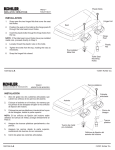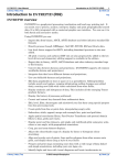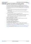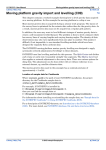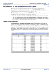
1
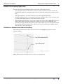
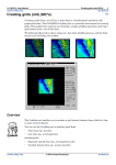
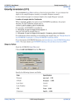
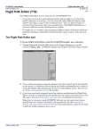
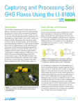
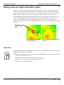
INTREPID User Manual
Library | Help | Top
Editing with the Flight Path Editor (G10)
1
| Back |
Editing with the Flight Path Editor (G10)
Top
As part of the process of refining survey data you may discover some line sections
which are not satisfactory and which you would like to remove. For example, there
may be some overlap between lines, or a pair of lines may pass too close to each other.
Both of these situations may affect the quality of grids produced from the data.
The INTREPID Flight Path Editor displays a datasets positional information (ie; X
and Y fields) graphically in plan view. This view of the positional data for a line
dataset is referred to as the survey Flight Path. You can use the tool to delete
unwanted sections of lines. This guided tour will demonstrate this flight path editing
process.
Anomalies caused
by errors in line
3013
3013
3013
3012
3012
Grid created before flight
path edit process
Grid created after flight path edit
process
Overview
The INTREPID Flight Path Editor is one of the four INTREPID editors (Spreadsheet,
Flight Path, Profile and Clip Line).
The Flight Path Editor enables you to examine the flight paths for a line dataset and:
Library | Help | Top
•
Perform data validation tests,
•
Remove sections of lines not suitable for processing,
•
Query field values by clicking data points on lines,
•
Show noise in a spatial context.
© 2012 Intrepid Geophysics
| Back |
INTREPID User Manual
Library | Help | Top
Editing with the Flight Path Editor (G10)
2
| Back |
Reasons for trimming flight paths
You may decide to trim flight paths for one of the following reasons:
•
If a particular line was flown twice, and you wish to retain sections of both the
original line and the second attempt, you can trim the unwanted sections of each
line.
•
Data presentation - the data ‘looks neater’ with clipped flight lines.
•
A flight path may have a section that you know contains errors. If you remove this
section of the flight path you will obtain better results.
•
When flight paths overlap, cross over or pass too close to each other there may be
data points from both lines within the bounds of a grid cell. INTREPID will
normally use the closest data point to the centre of the cell. You can decide which
line provides the data point value for the grid cell by trimming the flight path of
the line that you do not require.
Guided tour dataset areas that need editing
The following illustrations show two locations in the ebagoola_S dataset that
require editing.
Note: Extra arrow required from 'too close' to enlargement
Library | Help | Top
© 2012 Intrepid Geophysics
| Back |
INTREPID User Manual
Library | Help | Top
Editing with the Flight Path Editor (G10)
3
| Back |
Deciding which line to clip in an overlap area
Before proceeding with the editing process we need to decide whether to remove the
end of line 3012 or 3013.
In a grid produced from the data the area where lines 3012 and 3013 overlap has a
small steep anomaly suggestive of spikes. We used the Profile Editor to examine the
smooth_mag field in the region where lines 3012 and 3013 overlap. We found spikes
in line 3013 in the overlap region. This shows us that line 3012 contains more
accurate data, and that we should remove the end of line 3013.
‘Spike’ anomaly in the
overlap area
Line 3012: No spikes in overlap
area
Line 3013: Spikes in overlap area
Tip: The above illustrations of the line profiles have different scales, set
automatically so that each profile will be clearly displayed. The spikes in line 3013
could alternatively be removed using the Profile Editor. It is still advisable,
however, to trim the ends of overlapping lines.
Library | Help | Top
© 2012 Intrepid Geophysics
| Back |
INTREPID User Manual
Library | Help | Top
Editing with the Flight Path Editor (G10)
4
| Back |
Context of this guided tour
In the context of your data processing cycle, this tour represents an important
first or second step in processing a set of newly imported data. You should perform
this process in conjunction with removal of noise and spikes using the Profile Editor.
Location of sample data for Guided Tours
We provide two complete sets of sample datasets, one in INTREPID format and one
in Geosoft format. INTREPID works equally well with both formats. When you want
to open a dataset, navigate to the directory containing the required data format.
Where install_path is the path of your INTREPID installation, the project
directories for the Guided Tours sample data are
install_path\sample_data\guided_tours\intrepid_datasets and
install_path\sample_data\guided_tours\geosoft_datasets.
For example, if INTREPID is installed in
C:\Program Files\Intrepid\Intrepid4.2.1452,
then you can find the INTREPID format sample data at
C:\Program Files\Intrepid\Intrepid4.2.1452\sample_data\
guided_tours\intrepid_datasets
This is the default location for the sample data. If you have installed INTREPID
normally, the data resides there. If you have installed INTREPID elsewhere, the
exercises will work just as well. Just use the appropriate pathnames.
For more information about installing the sample data, see "Sample datasets—
installing, locating, naming" in INTREPID Guided Tours Introduction (G01)
For a more detailed description of INTREPID datasets, see Introduction to the
INTREPID database (G20). For even more detail, see INTREPID database, file and
data structures (R05).
Should you complete this guided tour?
This guided tour is intended for intermediate level users. Its process is more complex
than that of an introductory level tour and its instructions are less detailed. If you are
a beginner or wish only to have a brief overview of INTREPID’s capabilities, you can
omit this guided tour. Omitting this guided tour will not affect your understanding of
later tours. Trimming flight paths is, however, an important process in refining
geophysical data. You should note that INTREPID includes a tool for this process.
Library | Help | Top
© 2012 Intrepid Geophysics
| Back |
INTREPID User Manual
Library | Help | Top
Editing with the Flight Path Editor (G10)
5
| Back |
What you will do
Flowchart Summary
Inputs
Process
Line
dataset
Examine a line
dataset spatially
Outputs
Edit lines
Save edited
dataset
Library | Help | Top
© 2012 Intrepid Geophysics
Spatially
edited line
dataset
| Back |
INTREPID User Manual
Library | Help | Top
Editing with the Flight Path Editor (G10)
6
| Back |
Steps to follow
Launch the
Flight Path
Editor
1
Start the Project Manager. Navigate to the directory
install_path\sample_data\guided_tours\intrepid_datasets. Start the
Flight Path Editor. Choose File > Load Line Dataset. When the Load Dataset
prompt appears, select the line dataset ebagoola_S.
See Locating datasets, viewing statistics, launching tools (G02) for instructions
about navigating to different directories.
Choose Flightpath_Editor from the Editors menu. After opening the dataset
ebagoola_S, it displays the flight line data in the Flight Path Editor window.
Tip: We have modified colours in the following line dataset illustrations so they
will print more clearly. The normal display colours for the Flight Path Editor are
white lines on a grey background.
Removing the end of a line where it overlaps another line
You will remove the part of line 3013 that overlaps line 3012.
Zoom in to the
problem line
overlap area
2
Zoom in to the region where lines 3012 and 3013 overlap.
Select Zoom mouse mode. Use the mouse to define a small rectangular region
around the overlap area. Move the mouse pointer to the top left corner of the zoom
area. Hold down the left button and drag diagonally across to the lower right
corner of the zoom area (i.e., ‘rubber band stretch’ a rectangular zoom area).
Release the mouse button.
Zoom area
Zoom mode
Library | Help | Top
© 2012 Intrepid Geophysics
| Back |
INTREPID User Manual
Library | Help | Top
Editing with the Flight Path Editor (G10)
7
| Back |
INTREPID will zoom the display in to the region you defined. You should be able
to see where the lines overlap. If you can’t see well enough, repeat the process to
zoom in a little more if necessary, or zoom out (choose Zoom Out) and try again.
Query the data
3
Select Query mouse mode and determine which line is 3013.
Select Query mouse mode. Select several points in the overlap area and observe
the line number reported, until you have identified lines 3012 and 3013.
Line number
report
Selected
point
Note: If the subsampling interval is set to 1, line 3013 may have a different shape
as shown below. To make it appear as in the guided tour illustrations, choose
Display Subsampling from the Line Display menu and change the subsampling
interval to 10. Choose OK.
Library | Help | Top
© 2012 Intrepid Geophysics
| Back |
INTREPID User Manual
Library | Help | Top
Choose the line
end segment to
be clipped
4
Editing with the Flight Path Editor (G10)
8
| Back |
Choose Select Ends mouse mode and select a point on line 3013 level with the end
of line 3012.
Choose Select Ends mouse mode. Choose (click) a point on line 3013 level with the
end of line 3012. Check in the Reports area that you have, in fact, selected a point
on line 3013. The fiducial value for the point should be approximately 536172.
Fiducial
value for
point
Clip point
selected
Select ends
mode
Clip the
unwanted line
end segment
5
Delete the unwanted segment of line 3013
Choose Delete End/Segment from the Edit menu.
INTREPID will delete the unwanted segment of line 3013 and display the deleted
segment in a different colour.
Zoom out
6
Zoom out so that you can view the full dataset.
Select Zoom mouse mode. Choose Zoom Out repeatedly until INTREPID displays
the whole dataset again.
Library | Help | Top
© 2012 Intrepid Geophysics
| Back |
INTREPID User Manual
Library | Help | Top
Editing with the Flight Path Editor (G10)
9
| Back |
Removing a segment of a line where it passes too close to another line
You will remove the segment of line 2793 that passes too close to the adjacent line
on the Southern side of it (line 2781).
Zoom in to the
region where
the lines are
too close
7
Zoom in to the region concerned.
Define a zoom area as you did in step 2.
Zoom area
Choose the line
segment to clip
8
Clip the
unwanted line
segment
9
Library | Help | Top
Choose a point at each end of the segment to be removed.
Choose Select Segment mouse mode. Choose (click) a point at each end of the
segment to be removed. If you make a mistake simply repeat the process until you
are satisfied with your choices. INTREPID reports the fiducial counts of the first
and second points under the headings FID1 and FID2.
Delete the unwanted line segment.
Choose Delete Segment from the Edit menu. INTREPID will delete the segment
and display the display the deleted segment in a different colour.
© 2012 Intrepid Geophysics
| Back |
INTREPID User Manual
Library | Help | Top
Editing with the Flight Path Editor (G10)
10
| Back |
Saving your results and using them as the new X and Y fields.
Save the edited
X and Y fields
10 Save the edited flight path information (X and Y fields) as x_trim1 and y_trim1.
From the File menu choose Save Output X and Y fields.
INTREPID displays the Save X dialog box. Ensure that the current directory is
install_path\sample_data\guided_tours\intrepid_datasets
\ebagoola_S. Specify the name x_trim1 inside the ebagoola_S dataset
directory then choose OK.
INTREPID displays the Save Y dialog box. Specify the name y_trim1 inside the
ebagoola_S dataset directory then choose OK.
Exit and go to
the Project
Manager
Library | Help | Top
11 Exit from the Flight Path Editor, return to the Project Manager and select the
dataset just edited.
From the File menu choose Quit. Click in the Project Manager window. Select
(click) the ebagoola_S dataset.
© 2012 Intrepid Geophysics
| Back |
INTREPID User Manual
Library | Help | Top
The Project
Manager can
switch the
dataset to the
new X and Y
fields
Editing with the Flight Path Editor (G10)
11
| Back |
12 Observe how you can use the Project Manager to respecify the X and Y aliases as
x_trim and y_trim.
This step refers to the solution fields x_trim and y_trim we have provided which
are identical to x_trim1 and y_trim1.
At this stage the ‘nominated’ geographic location fields for the dataset are still x
and y. If you wish to adopt the new x_trim and y_trim as the ‘preferred’
geographic location fields, you can simply change them in the fields panel of the
Project Manager.
In the Project Manager, the Alias list displays the fields which already have
assigned alias names.
Click in the Alias column of the Project Manager. A list of reserved alias fields will
appear. By simply clicking on the Alias column next to x_trim, you can re-assign
the X alias to x_trim.
You can then de-assign the X alias by clicking Alias and choosing the blank entry.
Repeat the process for the Y alias and the y_trim field.
Throughout the INTREPID tools the selected geographic location fields are
identified using the X and Y aliases. The Project Manager enables you to assign
geographic location field names to these aliases. Whenever an INTREPID tool
processes this dataset it will use the geographic location fields you assign here. To
assign a new field to an alias, choose the corresponding alias button, then select
the field you require from the file chooser dialog box.
Tip: By not changing the X and Y aliases on this occasion you leave the
ebagoola_S dataset ready for others to go through the guided tour. From this
point onwards in the guided tour case study you will be using ebagoola_ST, a
copy of ebagoola_S which uses a set of trimmed flight paths.
Viewing the results of the flight path editing process in a grid
You can specify the input, output and parameters for creating the grid in this stage of
the guided tour using the job file ch11_2.job. If you wish, start the Gridding tool and
load the job file as described in "Task specification (job) file short cuts" in INTREPID
Guided Tours Introduction (G01). Choose Apply. The Gridding tool will create the
desired grid. Continue from Step 14.
Grid from the
trimmed
dataset then
examine the
grid
Library | Help | Top
13 (Optional:) Create a grid dataset called smooth_grid_t1 from the smooth_mag
field of the ebagoola_ST dataset.
Recall the instructions in Creating grids (G07) for creating grid datasets.
© 2012 Intrepid Geophysics
| Back |
INTREPID User Manual
Library | Help | Top
Editing with the Flight Path Editor (G10)
12
| Back |
14 (Optional:) Use the Windows Visualisation Tool or UNIX Visualisation tool to
compare the grid created from untrimmed flight paths (smooth_grid) with a grid
created from trimmed flight paths (smooth_grid_t) (identical to
smooth_grid_t1 you created).
Note: you will use the ebagoola_ST dataset (which has trimmed flight paths)
from now on in these tours.
Recall the instructions in The Visualisation tool (G05) for viewing these datasets.
Tip: You can launch two copies of the tool, load a different grid into each one and
place them side by side on the screen for best comparison. The following
illustration ‘before and after’ pictures of the parts of the dataset affected by the
errors in line 3013.
Anomalies
caused by
errors in line
3013
3013
3012
Grid created before flight
path edit process
(smooth_grid) using
original geolocation fields x
and y
Library | Help | Top
© 2012 Intrepid Geophysics
3013
3012
Grid created after flight path edit
process (smooth_grid_t)
using trimmed geolocation fields
x_trim and y_trim
| Back |
INTREPID User Manual
Library | Help | Top
Editing with the Flight Path Editor (G10)
13
| Back |
Key points for this guided tour
In this guided tour you have used the Flight Path Editor to:
•
View a line dataset spatially,
•
Interrogate data points and report field values,
•
Correct spatial problems by removing line segments.
The Flight Path Editor can also:
•
Perform a variety of quality control validation checks on your data.
Frequently Asked Questions
Q : Can I get hard copy from the quality control validation components of this
tool?
A : Yes. The INTREPID Flight Path Editor enables you to save the validation field as a
new Signal field. You can print this field using the Hard Copy Composition tool. (See
Map composition (G17)
Q : Can I view noise in a spatially located display?
A : Yes. You can display noise profiles of line datasets with the Flight Path Editor.
Q : Can I automatically trim lines that have gross navigation errors?
A : Yes, the Clip Line tool is designed to automate this process.
Library | Help | Top
© 2012 Intrepid Geophysics
| Back |