1
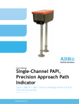
Solar Runway Guard Light
System
SRGLS
Installation Manual
96A0421
Retain for future use.
Rev. C, 4/11/12
Disclaimer
ENGLISH
This manual could contain technical inaccuracies or typographical errors. ADB Airfield
Solutions reserves the right to revise this manual from time to time in the contents thereof
without obligation of ADB Airfield Solutions to notify any person of such revision or change.
Details and values given in this manual have been compiled with care. They are not binding,
however, and ADB Airfield Solutions disclaims any liability for damages or detriments suffered
as a result of reliance on the information given herein or the use of products, processes or
equipment to which this manual refers. No warranty is made that the use of the information or
of the products, processes or equipment to which this manual refers will not infringe any third
party's patents or rights.
Warranties
Products of ADB Airfield Solutions manufacturer are guaranteed against mechanical, electrical,
and physical defects (excluding lamps) for a period of one year from the date of installation or
a maximum of 18 months from date of shipment and are guaranteed to be merchantable and
fit for the ordinary purposes for which such products are made.
ADB Airfield Solutions will correct by repair or replacement, at its option, equipment or parts
which fail because of mechanical, electrical or physical defects, provided that the goods have
been properly handled and stored prior to installation, properly installed and properly operated
after installation, and provided further that Buyer gives ADB Airfield Solutions written notice of
such defects after delivery of the goods to Buyer. Refer to the Safety section for more
information on Material Handling Precautions and Storage precautions that must be followed.
ADB Airfield Solutions reserves the right to examine goods upon which a claim is made. Said
goods must be presented in the same condition as when the defect therein was discovered.
ADB Airfield Solutions furthers reserves the right to require the return of such goods to establish
any claim.
ADB Airfield Solutions’ obligation under this guarantee is limited to making repair or
replacement within a reasonable time after receipt of such written notice and does not include
any other costs such as the cost of removal of defective part, installation of repaired product,
labor or consequential damages of any kind, the exclusive remedy being to require such new
parts to be furnished.
ADB Airfield Solutions’ liability under no circumstances will exceed the contract price of goods
claimed to be defective. Any returns under this guarantee are to be on a transportation charges
prepaid basis. For products not manufactured by, but sold by ADB Airfield Solutions, warranty
is limited to that extended by the original manufacturer.
This is ADB Airfield Solutions’ sole guarantee and warranty with respect to the goods; there are
no express warranties or warranties of fitness for any particular purpose or any implied
warranties of fitness for any particular purpose or any implied warranties other than those made
expressly herein. All such warranties being expressly disclaimed.
Trademarks
General notice: other product names used here are for identification purposes only and may be
trademarks of their respective companies.
Proprietary Information
This information carrier contains proprietary information, which shall not be used for other
purposes than those for which it has been released, nor be reproduced or disclosed to third
parties without the prior written consent of ADB Airfield Solutions.
No part of this publication may be reproduced, stored in a retrieval system, or transmitted in any
form or by any means, mechanical, photocopy, recording, or otherwise, without the prior written
permission of ADB Airfield Solutions. No patent liability is assumed with respect to the use of
the information contained herein. Neither is any liability assumed for damages resulting from
the use of the information contained herein.
ADB Airfield Solutions shall not be liable to the purchaser of this product or third parties for
damages, losses, costs, or expenses incurred by purchaser or third parties as a result of
accident, misuse, or abuse of this product or unauthorized modifications, repairs, or alterations
to this product. ADB Airfield Solutions shall not be liable against any damages arising from the
use of any options or parts other than those designated as approved products.
Copyright © 2010 by ADB Airfield Solutions. All rights reserved.
96A0421
Rev. C
Solar Runway Guard Light System
Table of Contents
Table of Contents
TABLE OF CONTENTS
Solar Runway Guard Light System ...........................................................................1
Safety .......................................................................................................... 1
Introduction ................................................................................................. 1
To use this equipment safely: ..................................................................... 1
Additional Reference Materials: .................................................................. 1
Qualified Personnel ..................................................................................... 1
Intended Use ............................................................................................... 1
Storage ........................................................................................................ 2
Operation .................................................................................................... 2
Material Handling Precautions .................................................................... 2
Action in the Event of a System or Component Malfunction ....................... 2
Maintenance and Repair ............................................................................. 2
Solar Runway Guard Light System (SRGLS) .......................................... 3
About this manual ....................................................................................... 3
How to work with the manual ................................................................. 3
Record of changes ................................................................................ 3
Icons used in the manual ....................................................................... 3
Introduction ................................................................................................. 4
FCC Compliance ......................................................................................... 5
FCC Statement ...................................................................................... 5
Theory of Operation ............................................................................... 6
SRGLS Performance .................................................................................. 7
TILT ANGLES ........................................................................................ 8
Warranty Disclaimer .............................................................................. 9
Standards .............................................................................................. 9
Safety and Usage Precautions .............................................................. 9
SEPS Specifications ................................................................................. 10
Wireless Regions ...................................................................................... 11
Operation .................................................................................................. 12
System Check and Start-up ................................................................. 12
Check Battery Polarity ................................................................... 12
Check Solar Panel Polarity ............................................................ 12
System Status................................................................................ 12
Battery Status ................................................................................ 12
Configuration ....................................................................................... 12
Non-Wireless Operation ...................................................................... 12
Wireless Operation .............................................................................. 12
Glossary .................................................................................................... 13
RGL Installation........................................................................................ 15
Unpacking ................................................................................................. 15
Installing a Runway Guard Light ............................................................... 15
Installing an L-867B Base .................................................................... 16
Installing an SRGL on an L-867B Base ............................................... 16
Installing a Concrete Pad for the SRGL .............................................. 16
Installing an SRGL on a Concrete Pad ................................................ 16
Horizontal Aiming ................................................................................ 16
Adjusting the Horizontal Setting..................................................... 17
Vertical Aiming ..................................................................................... 18
Installing the Coupling .............................................................................. 20
SEPS Installation ...................................................................................... 21
Site Preparation ................................................................................... 21
© 2010 ADB Airfield Solutions All Rights Reserved
3
Solar Runway Guard Light System
Table of Contents
96A0421
Rev. C
Table of Contents
Assembly .............................................................................................21
Antenna Assembly ...............................................................................23
Grounding ............................................................................................23
Connect Load ......................................................................................24
Install Battery .......................................................................................24
SRGLS Maintenance ................................................................................27
Introduction ................................................................................................27
Maintenance Schedule ........................................................................27
Troubleshooting .........................................................................................28
Spare Parts ...............................................................................................29
Maintenance ..............................................................................................29
Inspection ............................................................................................29
Cleaning ...............................................................................................30
Batteries ....................................................................................................30
Energy Management System (EMS) Recycling ........................................31
Electrical Wiring Schematics .....................................................................32
Runway Guard Light Parts ........................................................................33
40
4
© 2010 ADB Airfield Solutions All Rights Reserved
96A0421
Rev. C
Safety
1.1 Introduction
This section contains general safety instructions for installing and using ADB Airfield
Solutions equipment. Some safety instructions may not apply to the equipment in this
manual. Task- and equipment-specific warnings are included in other sections of this manual
where appropriate.
Carefully read and observe all safety instructions in this manual, which alert you to safety
hazards and conditions that may result in personal injury, death or property and equipment
damage and are accompanied by the symbol shown below.
WARNING
Failure to observe a warning may result in personal injury, death or equipment damage.
CAUTION
Failure to observe a caution may result in equipment damage.
1.2 To use this equipment
safely:
WARNING
Read installation instructions in their entirety before starting installation.
• Refer to the FAA Advisory Circular AC 150/5340-26, Maintenance of Airport Visual Aids
Facilities, for instructions on safety precautions.
• Observe all safety regulations.
• Become familiar with the general safety instructions in this section of the manual before
installing, operating, maintaining or repairing this equipment.
• Read and carefully follow the instructions throughout this manual for performing specific
tasks and working with specific equipment.
• Make this manual available to personnel installing, operating, maintaining or repairing this
equipment.
• Follow all applicable safety procedures required by your company, industry standards and
government or other regulatory agencies.
• Protect equipment with safety devices as specified by applicable safety regulations.
1.3 Additional Reference
Materials:
1.4 Qualified Personnel
•
•
•
•
•
NFPA 70B, Electrical Equipment Maintenance
NFPA 70E, Electrical Safety Requirements for Employee Workplaces
ANSI/NFPA 79, Electrical Standards for Metalworking Machine Tools
OSHA 29 CFR, Part 1910, Occupational Health and Safety Standards
National and local electrical codes and standards.
The term qualified personnel is defined here as individuals who thoroughly understand the
equipment and its safe operation, maintenance and repair. Qualified personnel are physically
capable of performing the required tasks, familiar with all relevant safety rules and regulations
and have been trained to safely install, operate, maintain and repair the equipment. It is the
responsibility of the company operating this equipment to ensure that its personnel meet
these requirements.
Always use required personal protective equipment (PPE) and follow safe electrical work
practices. See 1.2 above.
1.5 Intended Use
WARNING
Using this equipment in ways other than described in this manual may result in personal
injury, death or property and equipment damage. Use this equipment only as described in
this manual.
ADB Airfield Solutions cannot be responsible for injuries or damages resulting from
nonstandard, unintended applications of its equipment. This equipment is designed and
intended only for the purpose described in this manual. Uses not described in this manual are
considered unintended uses and may result in serious personal injury, death or property and
equipment damage. Unintended uses may result from taking the following actions:
© 2010 ADB Airfield Solutions All Rights Reserved
1
Safety
1.0 Safety
Safety
96A0421
Rev. C
Safety
•
Using materials or auxiliary equipment that are inappropriate or incompatible with ADB
Airfield Solutions equipment
•
Allowing unqualified personnel to perform any task
1.6 Storage
CAUTION
If equipment is to be stored prior to installation, it must be unboxed and set in a sunny area
until needed.
Failure to follow this instruction can result in battery damage.
1.7 Operation
WARNING
• Only qualified personnel, physically capable of operating the equipment and with no
impairments in their judgment or reaction times, should operate this equipment.
• Read all system component manuals before operating this equipment. A thorough
understanding of system components and their operation will help you operate the system
safely and efficiently.
• Protect equipment with safety devices as specified by applicable safety regulations.
• If safety devices must be removed for installation, install them immediately after the work
is completed and check them for proper functioning.
• Never operate equipment with a known malfunction.
• Use this equipment only in the environments for which it is rated. Do not operate this
equipment in humid, flammable, or explosive environments unless it has been rated for
safe operation in these environments.
• Never touch exposed electrical connections on equipment while the power is ON.
1.8 Material Handling
Precautions
CAUTION
This equipment may contain electrostatic sensitive devices.
• Protect from electrostatic discharge.
• Electronic modules and components should be touched only when this is unavoidable e.g.
soldering, replacement.
• Electronic modules or components must not be brought in contact with highly insulating
materials such as plastic sheets, synthetic fiber clothing. They must be laid down on
conductive surfaces.
• The tip of the soldering iron must be grounded.
• Electronic modules and components must be stored and transported in conductive
packing.
1.9 Action in the Event of a
System or Component
Malfunction
WARNING
• Do not operate a system that contains malfunctioning components. If a component
malfunctions, turn the system OFF immediately.
• Allow only qualified personnel to make repairs. Repair or replace the malfunctioning
component according to instructions provided in its manual.
1.10 Maintenance and
Repair
WARNING
Allow only qualified personnel to perform maintenance, troubleshooting, and repair tasks.
• Only persons who are properly trained and familiar with ADB Airfield Solutions equipment
are permitted to service this equipment.
• Always use safety devices when working on this equipment.
• Follow the recommended maintenance procedures in your equipment manuals.
• Use only approved ADB Airfield Solutions replacement parts. Using unapproved parts or
making unapproved modifications to equipment may void agency approvals and create
safety hazards.
2
© 2010 ADB Airfield Solutions All Rights Reserved
96A0421
Rev. C
Solar Runway Guard Light System
About this manual
2.1 About this manual
About this manual
2.0 Solar Runway
Guard Light
System (SRGLS)
The manual shows the information necessary to:
•
•
•
Install
Carry Out Maintenance
Carry Out Troubleshooting
on the SRGLS light, in the manual referred to as the equipment.
2.1.1 How to work with the
manual
1. Familiarize yourself with the structure and content.
2. Carry out the actions completely and in the given sequence.
2.1.2 Record of changes
2.1.3 Icons used in the
manual
Page
Rev
Description
A
12/13
B
8, all
C
Updated Tilt Angle Charts, updated format
Checked
Approved
Date
New
DM
MLV
01/2011
Updated Solar Charts
RW
NH
02/21/12
RW
NH
04/11/12
For all WARNING symbols see the Safety section.
Carefully read and observe all safety instructions in this manual, which alert you to safety
hazards and conditions that may result in personal injury, death or property and equipment
damage and are accompanied by the symbol shown below.
WARNING
• Failure to observe a warning may result in personal injury,
death or equipment damage.
CAUTION
• Failure to observe a caution may result in equipment damage.
© 2010 ADB Airfield Solutions All Rights Reserved
3
Solar Runway Guard Light System
Introduction
2.2 Introduction
96A0421
Rev. C
Introduction
ADB Solar Runway Guard Lighting System (SRGLS) is an ideal choice for an airfield that
requires improved safety measures, but experience difficulties with grid access. ADB Solar
Runway Guard Lighting System (SRGLS) consists of an elevated unidirectional flashing
yellow light Solar-powered Runway Guard Light (SRGL) and a Solar Engine Power Supply
(SEPS). See Figure 1. The SRGL provides a distinctive warning to pilots that they are
approaching a runway holding position and are about to enter an active runway. The SEPS
incorporates the latest technology in solar technology, hardware and software to provide
power and control to the SRGL.
The SRGLS is typically installed in pairs, one on either side of the taxiway holding position.
The SRGLS can also be used in combination with L-852G (In-pavement Runway Guard
Light), L-852S (In-pavement Stop Bar Light), and L-862S (Elevated Stop Bar Light) to provide
additional safety under low-visibility conditions on the airfield.
NOTE: SEPS is a standalone enclosure designed to power the SRGL. The SEPS houses a
95 watt solar panel, a 12 VDC battery, and the Energy Management System (EMS) which
controls the flow of energy between the solar panel, the battery and SRGL. See Figure 2 for a
block diagram of the system. The EMS is made up of three components:
a. EMS Battery Charger
b. EMS SRGL LED Lamps driver
c. EMS Controller
d. Radio (Optional)
4
Figure 1:
Solar SRGL System overview diagram
Figure 2:
Solar SRGL System
© 2010 ADB Airfield Solutions All Rights Reserved
Solar Runway Guard Light System
FCC Compliance
2.3 FCC Compliance
This device complies with Part 15 of the FCC Rules. Operation is subject to the following two
conditions: (1) This device may not cause harmful interference, and (2) this device must
accept any interference received, including interference that may cause undesired operation.
Changes or modifications not expressly approved by ADB could void your authority to
operate the equipment.
2.3.1 FCC Statement
This equipment has been tested and found to comply with the limits for a Class B digital
device, pursuant to Part 15 of the FCC Rules. These limits are designed to provide
reasonable protection against harmful interference in a residential installation. This
equipment generates, uses, and can radiate radio frequency energy and, if not installed and
used in accordance with the instruction manual, may cause harmful interference to radio
communications; however, there is no guarantee that interference will not occur in a
particular installation. If this equipment does cause harmful interference to radio or television
reception, which can be determined by turning the equipment off or on, the user is
encouraged to try to correct the interference by one or more of the following measures:
•
•
•
Reorient or relocate the receiving antenna
•
Consult the dealer or an experienced radio/TV technician for help
Increase the separation between the equipment and receiver
Connect the equipment into an outlet on a circuit different from that to which the receiver
is connected
© 2010 ADB Airfield Solutions All Rights Reserved
5
FCC Compliance
96A0421
Rev. C
Solar Runway Guard Light System
FCC Compliance
2.3.2 Theory of Operation
96A0421
Rev. C
FCC Compliance
The ADB SEPS is factory configured to work autonomously for either dusk-to-dawn or for
24-hour period operation. On autonomous mode the product turns on at the intensity that is
sustainable in that solar region. See Table 1 and Figure 3 for % intensity by solar region.
SEPS has the option to be controlled remotely with a Hand Held Radio Control. The wireless
handheld controller allows for intensity adjustment, some configuring, and grouping of loads.
One of the benefits of radio controller is that the user can temporary override the autonomous
intensity factory settings. However there is a limitation on the amount of hours the SRGLS
can operate at different intensities.
SEPS can be controlled using the Wireless Hand-Held Controller in a similar manner to
ADB’s wireless solar lights.
One or more wireless solar lights can be remotely operated from the ground or air with a
hand-held wireless controller using a secure radio transceiver with antenna and keypad.
The hand-held remote control option allows the user to temporarily override the intensity set
in the autonomous modes. In temporary mode, 10%, 30%, 100% intensities can be selected
for a 15 minute Time-Out or a maximum Time-Out.
The 15-minute Time-Out option is for only momentary intensity brightness operations of the
SRGLS for airports that actively manage their airfields. After 15 minutes, the SRGLS will be
return to the autonomous configuration.
The maximum Time-Out option is for airports that require “the most intensity for as long as
possible”. The SEPS software prevents the battery from being ON indefinitely at the chosen
intensity, thereby preventing battery full discharge. To determine the maximum activation
time for each selected intensity and region, See Table 2.4.1.
The minimum autonomy or operational days without charging is 7 days and the battery daily
depth of discharge is sized for a minimum of 5 years of service.
WARNING
Continuous selection of the temporary mode will exceed the maximum allocated time period of operation
in table 2, and will cause the battery to drain.
6
© 2010 ADB Airfield Solutions All Rights Reserved
96A0421
Rev. C
This gives the customer an idea of expected performance depending on which solar region
they are in.
Figure 3:
SRGLS Performance
2.4 SRGLS
Performance
Solar Runway Guard Light System
SRGLS Performance
Solar Region Map
Table 1:
REGION
1
Percent % Intensity per
region in Autonomous mode
Autonomous
Dusk-to-Dawn
% Intensity
73%
Autonomous
24Hr
% Intensity
49%
2
94%
60%
3
100%
70%
4
100%
82%
5
100%
92%
From Cat Sheet 3036
© 2010 ADB Airfield Solutions All Rights Reserved
7
Solar Runway Guard Light System
SRGLS Performance
2.4.1 TILT ANGLES
96A0421
Rev. C
Figure 4:
Solar Tilt Angle Chart
SRGLS Performance
55º
50º
45º
40º
35º
25º
20º
15º
20º
25º
35º
40º
45º
55º
50º
50º
55º
45º
40º
35º
25º
20º
15º
25º
20º
50º
45º
40º
15º
55º
50º
35º
25º
20º
20º
45º
15º
40º
35º
35º
40º
25º
20º
45º
50º
15º
25º
55º
35º
20º
40º
45º
8
© 2010 ADB Airfield Solutions All Rights Reserved
Solar Runway Guard Light System
SRGLS Performance
2.4.2 Warranty Disclaimer
This manual will familiarize you with the features and operation standards of your equipment.
Failure to comply with the use, storage, maintenance, installation, of placement instructions
detailed in this manual could void the applicable user warranty.
2.4.3 Standards
Perform all installation, wiring and maintenance in conformance with local building and
electrical codes. Adherence to the National Electrical Code (NEC) or Canadian Electrical
Code (CEC) is mandatory to comply with any certification markings. Non-adherence to code
may void the warranty. Qualified, licensed professionals should perform all installation work.
2.4.4 Safety and Usage
Precautions
Batteries are shipped fully-charged. Use extreme caution when handling the batteries as they
are capable of generating hazardous short-circuit currents. Remove all jewellery (bracelets,
metal-strap watches, etc.) before attempting to handle the batteries.
Solar Modules produce DC electricity when exposed to light and can, therefore, produce an
electrical shock or burn. To render Solar Modules inoperative, remove them from sunlight, or
fully cover their front surface with an opaque material.
Before lifting any heavy or bulky equipment, ensure that the load is secured so that moving
parts do not shift and it can be lifted as far as needed without back strain or loss of grip.
Installation may require more than one person.
Re-check all completed wiring for proper polarity prior to energizing the system.
This equipment has been tested and found to comply with the limits for a Class B digital
device, pursuant to part 15 of the FCC Rules. These limits are designed to provide
reasonable protection against harmful interference in a residential installation. This
equipment generates, uses and can radiate radio frequency energy and, if not installed and
used in accordance with the instructions, may cause harmful interference to radio
communications. However, there is no guarantee that interference will not occur in a
particular installation.
If this equipment does cause harmful interference to radio or television reception, which can
be determined by turning the equipment off and on, the user is encouraged to try to correct
the interference by one or more of the following measures:
•
•
•
Reorient or relocate the receiving antenna.
Increase the separation between the equipment and receiver.
Consult the dealer or an experienced technician for help.
© 2010 ADB Airfield Solutions All Rights Reserved
9
SRGLS Performance
96A0421
Rev. C
Solar Runway Guard Light System
SEPS Specifications
SEPS Specifications
2.5 SEPS
Specifications
96A0421
Rev. C
Equipment Data
Solar Engine Power Supply (SEPS)
Name
Installed weight
Shipping weight
Installed dimenions*
Shipping dimensions
Temperature
Specification
132 lbs. (59.8 kg)
Box 1 (SEPS) - 76 lbs. (34.4 kg)
Box 2 (battery) - 68 lbs. (30.8 kg)
29.9 H x 42.9 W x 17.4 D in. (75.9 H x 108.9 W x 44.1 D cm)
*with wireless antenna at 55° tilt
Box 1 (SEPS) 25.5 H x 46.9 W x 14.0 D in. (64.7 H x 119.1 W x 35.56 D cm)
Box 2 (battery) 8.3 H x 13.1 W x 7.4 D in. (21 H x 33.2 W x 18.8 D cm)
Operating: -22° to 122°F (-30° to 50°C)
Storage: -40° to 176°F (-40° to 80°C)
Chassis
Weather and corrosion-resistant construction of stainless steel and powder coated
aluminum
Mounting
ADB frangible couplings and floor flange mounts
Wind loading
300 mph min. installed at 55° tilt
Tilt
15°, 35°, 55°
Diagnostics
On-board feedback indicators for: Battery Status, System Status, Battery Reverse
Polarity, and Solar Panel Reverse Polarity
Certifications
RoHS, WEEE, CE, FCC
Power 12 VDC 105 A-hr. at C/100 discharge rate
Battery
Type Replaceable and recyclable, absorbent glass mat (AGM) SLA. Standard with
one battery, upgradable to two batteries when increased system autonomy is
required.
Lifetime 4,000 cycles to 20% depth of discharge at 68°F
Charger Temperature-compensated, maximum power point tracking (TC-MPPT)
LED Driver
Channels
Power
2 independent channels
Channel A: 18 – 38 VDC from 0.3 – 1.4 A and 5 – 100 % duty cycle, constant
current
Channel B: 18 – 38 VDC from 0.3 – 1.4 A and 5 – 100 % duty cycle, constant
current
Automatic Light Control
(ALC)
ALC dynamically reduces brightness in response to unusually low amounts of
sunlight to ensure continued autonomous operation.
Available on Channels A and B.
Control,
Autonomous Mode
Dusk-to-dawn, steady on or fl ashing, ALC on or off; 24 hrs., steady on or flashing,
ALC on or off; Multiple flash patterns available
Load Cabling
22 ft. (6.7 m) cable can exit onto the surface or down into a ground pot
Power: 17 VDC, 95 W
PV Panel
Type: High Efficiency Monocrystalline, IEC 61215
Lifetime: 10 yrs. at 90% output
Range: 2.5 miles minimum with 1W wirelesshand-held controller
Wireless
Frequency: 900 MHz ISM Band (902 – 928 MHz),FHSS
Encryption: 256-bit AES
Control,
On-demand Mode
10
- Seamless integration with existing ADB wireless solar products.
- Up to 8 independent groups.
- Flash Mode, Emergency Mode, Autonomous Mode
- On-demand Temporary Mode (High, Medium, and Low)
- Confi guration Mode, ARCAL
© 2010 ADB Airfield Solutions All Rights Reserved
96A0421
Rev. C
Solar Runway Guard Light System
Wireless Regions
SRGL Dimensions
Wireless Regions
Figure 5:
685.80
27.000
333.35
13.124
609.60
24.000
L867B HD BASE PLT RGL
& GASKET ORDERED SEPARATELY
314.33
12.375
2.6 Wireless Regions
NOTE: This product is only approved for installation in ISM Region 2
900 MHz (902 – 928 MHz)
© 2010 ADB Airfield Solutions All Rights Reserved
11
Solar Runway Guard Light System
Operation
96A0421
Rev. C
2.7 Operation
Operation
2.7.1 System Check and
Start-up
Once the battery and fuse are installed, the system will automatically turn on, perform a
system test, search for connected loads, search for power from the solar panel, and begin its
default operation. Default operation is dusk-to-dawn autonomous mode. If it is day time, the
product will detect this and turn the load off.
The EMS inside SEPS has several system indicators:
Indicators
2.7.1.1 Check Battery Polarity
Red indicates the battery polarity is reversed.
No light indicates the battery polarity is correct.
2.7.1.2 Check Solar Panel
Polarity
Red indicates the solar panel polarity is reversed.
2.7.1.3 System Status
Flashing red indicates that either LVD mode is enabled and the batteries are very low or the
unit is in 24 hr. shutdown mode. 24 hr. shutdown mode is when the product does not detect
any solar transitions and determines it is in shipping or inside.
No light indicates the solar panel polarity is correct.
Flashing green indicates the system status is good.
2.7.1.4 Battery Status
Flashing red indicates the battery state of charge is very low (0 - 32 %).
Flashing yellow indicates the battery state of charge is minimal (33 - 65 %).
Flashing green indicates the battery state of charge is good (66 – 100 %).
2.7.2 Configuration
SEPS comes configured for its the SRGL from the factory.
2.7.3 Non-Wireless
Operation
For non-wireless products, the unit operates automatically with no need for operator
interaction under normal conditions.
With normal daylight illumination, the solar panel is capable of producing sufficient current to
charge the battery.
2.7.4 Wireless Operation
SEPS is controlled using the Wireless Handheld Controller in a similar manner as the
wireless SAWL lights.
The primary differences for SEPS are:
— There are no infrared (IR) loads. Selecting “IR” will turn the load off.
— “AUTO LOW”, “AUTO MED”, and “AUTO HIGH” are the same. They are all one, preconfigured autonomous intensity level based on the load and which solar region it is
installed in.
— “TEMP HIGH” is 100% intensity.
12
© 2010 ADB Airfield Solutions All Rights Reserved
Solar Runway Guard Light System
Glossary
— The black button on the EMS is pressed once to put SEPS in a “listening” mode where
it can be added to groups. Grouping is similar to the SAWL lights. SAWL and SEPS
can be controlled with the same Controller and also in the same group.
Please see the Wireless Handheld Controller Quick Reference Card and User Manual for
details.
NOTE: Wireless Hand-Held Controller Ordering Code Part # SAWL-HC
Battery Replacement Kit for Wireless Hand-held Controller Part # 48247
2.8 Glossary
Aircraft Radio Control of Aerodrome Lighting (ARCAL): The Aircraft Radio Control of
Aerodrome Lighting (ARCAL) feature works in conjunction with an ARCAL VHF receiver to
allow aircraft pilots to control the airfield lights. Contact your representative for more
information about this feature.
Automatic Light Control (ALC): Automatic Light Control (ALC) is a patented algorithm that
allows the light to adjust its energy consumption to the amount of sunlight available to charge
the batteries. This ensures the light will continue to operate through periods of limited
sunlight.
Autonomy: The amount of time in hours or days that the product can continue normal
operation in the absence of sunlight.
Electrostatic Discharge (ESD): Electrostatic discharge (in layman's terms, a shock) is a
build-up of charge difference between a person and an object, often caused by friction
between synthetic materials, or electronic equipment. ESD can easily destroy semiconductor
products, even when the discharge is too small to be felt.
EMS Energy Management System
Light Emitting Diode (LED): A Light Emitting Diode (LED) is a solid-state semiconductor
device that converts electrical energy directly into light.
Self-discharge: During storage, the charge in the batteries will experience a normal, gradual
decrease. The chemistry of the batteries creates a small electrical current within them, and
the electronics of the product will draw an even smaller amount of electricity to keep itself
ready for use. The self-discharge is extremely low compared to the electrical currents when
the product is in operation, but over time it becomes significant enough to require the regular
recharge intervals.
SEPS Solar Engine Power Supply
SRGLS Solar Runway Guard Lighting System
Unique Code Sequence (UCS): The UCS feature allows one or more controllers to be
uniquely associated to one or more products. When UCS is enabled, the controller sends a
UCS with each radio transmission; only lights configured to accept that particular UCS will
respond to the transmission.
© 2010 ADB Airfield Solutions All Rights Reserved
13
Glossary
96A0421
Rev. C
Solar Runway Guard Light System
Glossary
96A0421
Rev. C
Glossary
14
© 2010 ADB Airfield Solutions All Rights Reserved
96A0421
Rev. C
Solar Runway Guard Light System
Unpacking
3.0 RGL
Installation
Unpacking
WARNING
Read the instructions in their entirety before starting installation.
Allow only qualified personnel to perform the following tasks.
Observe and follow the safety instructions in this document and all other related
documentation.
Also see FAA AC 150/5340-30, Design and Installation Details for Airport Visual
Aids.
This section provides instructions for installing the Solar-powered Runway Guard Light
(SRGL). Refer to the airport project plans and specifications for the specific installation
instructions.
Figure 6:
SRGL Dimensions
685.80
27.000
333.35
13.124
609.60
24.000
L867B HD BASE PLT RGL
& GASKET ORDERED SEPARATELY
314.33
12.375
3.1 Unpacking
The equipment is shipped ready for installation. Handle equipment very carefully to prevent
component damage. Unpack the carton upon receipt and check the contents and their
condition. Note any exterior damage to the carton that might lead to detection of equipment
damage.
If you note any damage to any equipment, file a claim with the carrier immediately. The
carrier may need to inspect the equipment.
3.2 Installing a
Runway Guard Light
Solar Runway Guard Light System (SRGLS) are installed at a runway holding position to
provide a distinctive warning to anyone that they are about to enter an active runway.
Normally the SRGLs are installed in pairs, one on either side of the taxiway. Refer to FAA
Advisory Circular, AC 150/5340-30, Design and Installation Details for Airport Visual Aids for
dimensional location of the elevated SRGL.
The SRGL is designed to be installed on an L-867B light base housing using an L-867B
heavy duty base plate that has been specifically designed per FAA specifications found in
FAA AC 150/5345-46C to withstand the high bending moments induced on the elevated
fixture.
NOTE: SRGL shall not be stake mounted per FAA AC 150/5345-46C.
© 2010 ADB Airfield Solutions All Rights Reserved
15
Solar Runway Guard Light System
Installing a Runway Guard Light
Installing a Runway
Guard Light
3.2.1 Installing an L-867B
Base
96A0421
Rev. C
To install the base, perform the following procedure:
1. Install the L-867B per the site plans and specifications. See FAA AC 150/5340-30 for
additional installation instructions.
2. Orient the cable entrance hubs of the base in the proper directions.
3. Level the light base so that the mounting flange surface is flush with the finished grade.
4. With the light base at proper orientation and held at proper elevation, pour concrete
around the outside of the base. If the base is installed outside the concrete pad, backfill
with compacted earth.
5. Slope top of concrete away from the flange portion of the base.
6. In closed duct systems installed in soil conditions of good drainage, use light bases
having a drain hole to prevent water accumulation.
7. Pull the cable SEPS.
8. Install the base plate w/gasket on top of the light base. The baseplate is designed to
receive the SRGL frangible column.
3.2.2 Installing an SRGL
on an L-867B Base
To install the SRGL, perform the following procedure:
1. Install the SRGL assembly and frangible column, and connect the cablefrom the SEPS in
the terminal block located inside the SRGL.
2. Bolt the base plate to the light base.
NOTE: Only use two of the mounting bolts at this time and only hand tighten these bolts.
After horizontal aiming has been completed and verified, install the remaining baseplate bolts
and then torque bolts to 180 – 190 in-Lbs.
3. Aim the SRGL both vertically and horizontally per site plans and specifications.
Aiming procedure is as follows: See: “Horizontal Aiming” on page 16 and “Vertical Aiming”
on page 18.
3.2.3 Installing a Concrete
Pad for the SRGL
If the SRGLS will be installed without using any L-867B base cans, and the cable between
the SEPS and SRGL will be above ground, a mount concrete PAD will be needed for both
SRGL and SEPS. Reference the following guidelines.
NOTE: Follow site plans and specifications for concrete dimensions.
To pour concrete pad, consider the following procedures:
1. Use the PAD mounting pattern shown in application drawing to determine minimum
diameter of the concrete PAD.
2. Pour a minimum of 4” (101.6mm) depth of concrete, extending below the frost line to
prevent frost heave.
3. Use anchor 6 (six) bolts and 6 (six) lock washers to mount base plate to concrete pad.
3.2.4 Installing an SRGL
on a Concrete Pad
1. Install the SRGL assembly and frangible column.
2. Connect the cable from SEPS through the side of the SRGL
3. Terminate the cable on the terminal block located inside the SRGL See application
drawing “Electrical Wiring Schematics” on page 32.
Aim the SRGL both vertically and horizontally per site plans and specifications. Use
procedures in “Horizontal Aiming” on page 16 and “Vertical Aiming” on page 18.
3.2.5 Horizontal Aiming
16
NOTE: See Figure 11 and “Installing the Coupling ” on page 20 before proceeding. Back out
or remove the two hex head set screws that are in the side of the baseplate hub so that the
coupling can be screwed into the hub.
© 2010 ADB Airfield Solutions All Rights Reserved
Solar Runway Guard Light System
Installing a Runway Guard Light
Before screwing the coupling into the baseplate, use a black magic-marker to put “tick mark”
in line with the slot and above the frangible groove as shown in the photo below.
NOTE: The tick-mark will aid in locating the slot after the coupling is screwed into the
baseplate hub.
Figure 7:
Place “Tick-Mark” Here
1. Apply anti-seize paste on threads and then screw the frangible coupling into the hub on
the baseplate until the frangible groove is just above the top edge of the hub.
Locate the set screw hole in the side of the hub that is nearest to the slot in the coupling by
locating the “Tick-Mark.” Rotate the coupling, either clock or counter-clockwise, until the “tickmark” on the coupling is in line with the set screw hole in the hub.
NOTE: It is important to make sure that the slot and the set screw hole are aligned because
of the close fit between the slot and the ¼-20 screw. The close fit between the screw and the
slot prevents the coupling from turning and loosening when the face of the SRGL is subjected
to jet engine exhaust or wind.
2. Thread the set screw into the hub and through the slot in the coupling. The screw must
pass through the slot so it does not tightened against the screw threads on the coupling.
Hand-tighten this screw only until final horizontal aiming has been completed.
3.2.5.1 Adjusting the Horizontal
Setting
To adjust the horizontal setting, perform the following procedure:
1. Thread the set screw into the hub and through the slot in the coupling. The screw must
pass through the slot so it does not tightened against the screw threads on the coupling.
Hand-tighten this screw only until final horizontal aiming has been completed.
2. See Figure 11 and photo below. Locate the four Phillips head screws – ref Figure 8 and
loosed them so that the frangible coupling can be inserted into the hub. Also, if necessary,
loosen the two 3/8-16 allen hex head set screws in the SRGL adjustable joint – Ref
Figure 11.
Figure 8:
Zero (“0”) Screw
Zero (“0”) Hole
NOTE: The Zero (“0”) on the horizontal label that is affixed to the frangible coupling, has been
aligned at the factory with the index pin pressed into the lower hub of the adjustable arm.
This alignment will then allow the 10-32 screw to be screwed into the top center Zero (“0”)
hole and pass through the Zero (“0”) hole that is located at the top of the coupling. See
figures above.
© 2010 ADB Airfield Solutions All Rights Reserved
17
Installing a Runway
Guard Light
96A0421
Rev. C
Solar Runway Guard Light System
Installing a Runway Guard Light
96A0421
Rev. C
Installing a Runway
Guard Light
3. Rotate SRGL assembly until the indicator pin that is found at the bottom edge of the
adjustable arm hub is aligned with the desired angle. The horizontal angle label that is
affixed to the coupling is marked in 5 degree increments. See the following Figure 9.
Figure 9:
Indicator Pin
Horizontal Angle
Label
NOTE: The appropriate screw to tighten all the way into the mating hole in the frangible
coupling is determined by the degrees adjusted. For example, if the horizontal is adjusted to
20 degrees, the top screw marked 20, 0, 20 should go in all the way. Hand tighten all four
screws. See photos above.
Verify that the selected angle meets the requirements of the site plans and specifications.
If the horizontal aiming angle is not correct make one or both of the following adjustments:
4. Remove the two screws in the side of the baseplate hub and rotate the coupling slot to
line up with the other tapped hole in the hub. Repeat horizontal aiming procedure above.
5. If additional adjustment is needed then remove the two mounting bolts used to fasten the
baseplate to the L867B light base. Rotate the baseplate either clock or counter-clock
wise at least 30 degrees. Repeat the horizontal aiming procedure above.
6. Once horizontal aiming is completed install and torque all mounting hardware that
secures the baseplate to the L867B light base.
3.2.6 Vertical Aiming
To adjust the vertical setting, perform the following procedure:
1. See Figure 11. Loosen two allen hex set screws on side shown in photo and on opposite
side.
Figure 10:
Set Screw - 2 Places 180
Degrees Apart
1. Loosen hex bolt (6) on the face (side) of the mount.
2. Adjust the vertical setting to the desired number of degrees in one-degree increments by
lining up the indicator pin (9) from 0 to +20 degrees.
3. Tighten the hex bolt (6).
18
© 2010 ADB Airfield Solutions All Rights Reserved
96A0421
Rev. C
Solar Runway Guard Light System
Installing a Runway Guard Light
NOTE: See Figure 11 for additional installation instructions and bolt torque values.
5. After the SRGL has been aimed and operation has been verified, install the tether by
attaching one end of the tether to one of the bolts on the center housing of the SRGL and
attach the other end to nearest bolts securing the baseplate to the light base housing.
NOTE: There are two set screws in the side of the hub. These set screws are used when the
SRGL is being aimed horizontally.
NOTE: Bolt/Screw Torque Values,
See Figure 11 for location and torque vales for identified screws.
Some screws have multiple locations.
Figure 11:
Bolt Torque Values
Indicator Pin for Vertical
Aiming
Phillips Head Screws – Hand
Tighten
Allen Set Screws
Torque to 40 ft-lbs
Indicator Pin
Horizontal Angle
Label
Allen Set Screw – Torque to
10 ft-lbs
Hex Head Screw –
Torque to 70 ft-lbs
Hex Head Screw – Torque
to 15 ft-lbs
© 2010 ADB Airfield Solutions All Rights Reserved
Hex Head Screw – Hand
Tighten
19
Installing a Runway
Guard Light
4. Tighten the hex bolts (1).
Solar Runway Guard Light System
Installing the Coupling
Installing the Coupling
3.3 Installing the
Coupling
96A0421
Rev. C
Figure 12:
SRGL L867 Light Base Installation
Cable Is To Pass Thru Wire Grip Prior To
Terminating On Terminal Block.
P/n 61A0478, Sure Grip Cushioned Metal Wire Grip
For Solar Unit Cable Side Entry
Unit Is Supplied With Cable Strain Relief
For Solar Unit Cable Pass Thru, Prior
To Connection To Terminal Block.
P/n 77A0147 Compression Fitting 1/2"
For Solar Unit Cable Bottom Entry
Remove Cable Strain Relief And Replace
With Hole Plug Provided.
P/n 77A0098, Pipe Plug 1/2" NPT Galv
Ground Lug
REAR VIEW
RUNWAY
GUARD LIGHT
L867B HD BASE PLT RGL
& GASKET ORDERED
SEPARATELY, GASKET
NOT SHOWN
B
Cable Length Approx.
22 Feet, Supplied With
Solar Unit. Not To Be
Exceeded.
Anchor Bolts And Lock Washers
Supplied By Customer
L-867 Light Base
Not Supplied
Cable Length Approx.
22 Feet, Supplied With
Solar Unit. Not To Be
Exceeded.
20
© 2010 ADB Airfield Solutions All Rights Reserved
96A0421
Rev. C
Solar Runway Guard Light System
SEPS Installation
3.4.1 Site Preparation
SEPS Installation
3.4 SEPS Installation
Follow these steps to prepare the installation site:
1. Ensure that the site has year-round, unrestricted sun exposure throughout the day.
NOTE: Shading even a small portion of the solar panel will significantly reduce its ability to
collect solar power.
2. Any pad design should meet FAA AC 150/5340-30:
a. Above ground wiring: install a level concrete pad within 20 ft. of the load that SEPS
will be powering. Mounting to wood, soil, or asphalt may work but is not recommended
since they will not have the strength required for high wind loads.
b. Below ground wiring: install a level concrete pad with L-867B base can and base plate
or conduit within 20 ft. of the load that SEPS will be powering.
3. Use the below template (in inches) to mark 4 mounting points for the 2 floor flanges. Note
that the centerline of SEPS should be parallel to the equator, so that the installed solar
panel will face south in northern latitudes and north in southern latitudes.
4. At each of the 4 mounting points, install a ½-13 UNC anchor bolt or stud.
3.4.2 Assembly
Follow these steps to assembly the SEPS:
1. Open SEPS’s solar panel lid by loosening the 2 black, captive thumb screws under the
bottom lip.
NOTE: Slowly hold and open the lid since it has a gas shock that will push the lid open.
Lid is designed to best open and close once SEPS is fully installed and the lid can open
quickly when SEPS is lying flat on the ground during preparation.
2. Unpack two mounting posts and their fasteners from within SEPS.
Mounting Post inside SEPS
© 2010 ADB Airfield Solutions All Rights Reserved
21
Solar Runway Guard Light System
SEPS Installation
96A0421
Rev. C
SEPS Installation
3. Slide the mounting post down its oblong hole. Align mounting post’s bottom bolt hole with
the bottom bolt hole in the chassis. Loosely install the 5/16-18 UNC bolt from the outside
and the nut on the inside. Note that this bolt does not have extra length and when
tightened will pull the chassis frame members together.
4. Tilt the mounting post to its desired tilt angle and install top bolt and nut. Tighten both top
and bottom fasteners. Tilt angle is dependant on your location. See tilt angle map
Figure 4.
Tilt Angle
Mounting Post
Top Bolt and Nut
Mounting Post
Bottom Bolt and Nut
5. Repeat above steps for second mounting post.
6. Close the lid and finger tighten the thumb screws to better balance the unit.
7. Thread the frangible coupling into the floor flange until tight. Install the frangible coupling’s
3 bolts. Repeat for second subassembly.
8. Slide the frangible coupling subassembly onto the mounting post. Finger tighten 1 of the
frangible coupling’s screws to hold the subassembly onto the mounting post. Repeat for
second subassembly.
Tilt Angle
Mounting Post
Top Bolt and Nut
Mounting Post
Bottom Bolt and Nut
Mounting Post
Frangible Coupling
Frangible Coupling
Bolts
Floor Flange
9. Pick up the SEPS and set down over the 4 anchor bolts installed above. If required,
loosen frangible coupling bolts to adjust the rotation of frangible coupling. Do not loosen
the floor flange and frangible coupling thread.
22
© 2010 ADB Airfield Solutions All Rights Reserved
96A0421
Rev. C
Solar Runway Guard Light System
SEPS Installation
3.4.3 Antenna Assembly
If your SEPS has wireless control capability, it will have a wireless antenna subassembly that
needs to be installed. During manufacturing, the antenna is uninstalled and placed inside
SEPS to protect it from shipping damage. To install:
1. Open lid slowly and carefully unpack antenna subassembly.
2. Remove 8-32 UNC thumb screw and its toothed washer.
3. Slide antenna cable back through hole to remove slack.
4. Ensure antenna and bracket are vertical and re-install thumb screw and toothed washer.
5. Route cable as shown below.
Antenna
Note cable routing
Antenna Bracket
Antenna
Thumb Screw
3.4.4 Grounding
NOTE: Failure to install an appropriate grounding system may cause a safety risk in the
event of lightning strike, electrostatic discharge (ESD), or damaged cabling.
Failure to install an appropriate grounding system will increase the risk of system damage in
the event of lightning strike or ESD.
Surges resulting from lightning strikes in the proximity of the installation are one of the most
common causes of solar system failure. Installation of an appropriate grounding system
allows the static electricity that accumulates in the solar panel and mounting structure to
discharge. In addition to preventing the attraction of lightning, a properly grounded installation
may divert the surge associated with lightning from electrical circuitry, limiting the potential for
damage.
SEPS is negatively grounded. The solar panel frame, solar panel negative terminal, battery
negative terminal, chassis, and grounding lug are all electrically connected together.
SEPS should be grounded as follows:
1. Install a 14 – 2 AWG stranded grounding wire (not included) into the grounding lug under
the bottom lip of the chassis.
2. Connect the grounding wire to an appropriate grounding stake and install the stake in the
ground.
3. Note that the load cable does not provide any grounding for the load. The load should
also be properly grounded to prevent damage to it and SEPS.
Grounding techniques vary depending on site specifics and local electrical authorities.
Consultation with a local grounding expert is recommended.
© 2010 ADB Airfield Solutions All Rights Reserved
23
SEPS Installation
10. Tighten all frangible coupling bolts. Tighten all anchor bolts.
Solar Runway Guard Light System
SEPS Installation
3.4.5 Connect Load
96A0421
Rev. C
Connect the load to SEPS as follows:
SEPS Installation
1. Uncoil the load cable. The cable is stiff and should be routed above where the battery will
be installed.
2. For installations with cabling going into the ground, feed the load cable down either
mounting post. For a more finished look, the black, liquid tight cable fitting exiting the
SEPS unit may be replaced with the included 7/8 in. hole plug.
3. For installations with cabling lying on the surface of the ground, feed the load cable out
through the liquid tight cable fitting. Tighten fitting.
Note cable routing
Note cable routing
4. Pull the loose, 6 conductor end of the load cable into the appropriate junction box to
connect to the load.
5. Connect the 6 conductors to the load as per the electrical load connection diagrams.
3.4.6 Install Battery
NOTE: Exercise caution when handling batteries. They are capable of generating enormous
short-circuit currents. Remove all jewelry (bracelets, metal-strap watches, rings) before
attempting to handle or remove the battery packs.
Be careful not to short battery terminals with tools.
Batteries are heavy. Ensure that you use proper lifting techniques when moving batteries.
Do not discard batteries in the garbage – please recycle!
These batteries are rechargeable lead-acid AGM batteries. Consult your local municipal bylaws for information on recycling the cells when replacing.
SEPS has the capability to accept 1 or 2 batteries. SEPS is shipped from the factory with 1
battery since this is fine for most applications. For locations with long periods of poor solar
insolation, a second battery can be installed.
The battery must always be installed last, after site preparation, assembly, wireless
assembly, grounding, and load connection. There is no switch to power up the system. Once
the battery and its fuse are installed, SEPS’s EMS turns on. The EMS will immediately
attempt to charge the battery from the solar panel and perform a load scan to determine if any
load is connected.
24
© 2010 ADB Airfield Solutions All Rights Reserved
96A0421
Rev. C
Solar Runway Guard Light System
SEPS Installation
SEPS Installation
Battery 1 sits in the left hand cavity inside SEPS. To install battery 1:
1. Remove the battery fuse from the battery harness.
2. Release the battery strap buckle and loosen the buckle to the end of the strap.
3. Loop the strap buckle, battery harness leads, and temperature sensor above the solar
panel’s gas shock and out of the way.
4. Balance the battery on the bottom lip of the SEPS chassis and then slowly let it drop back
into its cavity. Do not let the battery fall backwards or crush any electrical connections.
5. Battery terminals should be closest to you, with the positive (+) on the left and
negative (–) on the right.
6. Loop the battery strap under the battery handle. Connect the battery strap buckle.
Tighten the battery strap and fold loose end underneath itself.
7. Loop the positive (+) harness lead under the battery handle. Apply anti-corrosion
compound (not included) to the terminal. Connect the harness lead to the terminal and
slide on the red, positive, battery terminal boot. Use supplied 5/16-18 UNC nut and lock
washer.
© 2010 ADB Airfield Solutions All Rights Reserved
25
Solar Runway Guard Light System
SEPS Installation
96A0421
Rev. C
SEPS Installation
8. Loop the negative (–) harness lead and its temperature sensor under the battery handle.
Apply anti-corrosion compound (not included) to the terminal. Connect the harness lead
first and then the temperature sensor to the terminal and slide on the black, negative,
battery terminal boot. Use supplied 5/16-18 UNC nut and lock washer.
9. Install the battery fuse.
26
© 2010 ADB Airfield Solutions All Rights Reserved
96A0421
Rev. C
Solar Runway Guard Light System
Introduction
4.1 Introduction
Introduction
4.0 SRGLS
Maintenance
To keep the light operating efficiently, follow a preventive maintenance schedule.
Refer to Table 2 and, refer to FAA AC 150/5340-26 for more detailed information.
WARNING
Read installation instructions in their entirety before starting installation.
• Refer to the FAA Advisory Circular AC 150/5340-26, Maintenance of Airport Visual Aids Facilities, for
instructions on safety precautions.
• Observe all safety regulations. To avoid injuries, always disconnect power before making any wiring
connections or touching any parts. Refer to FAA Advisory Circular AC 150/5340-26.
• Become familiar with the general safety instructions in this section of the manual before installing,
operating, maintaining or repairing this equipment.
• Read and carefully follow the instructions throughout this manual for performing specific tasks and
working with specific equipment.
• Make this manual available to personnel installing, operating, maintaining or repairing this equipment.
• Follow all applicable safety procedures required by your company, industry standards and government
or other regulatory agencies.
• Route electrical wiring along a protected path. Make sure they will not be damaged by moving
equipment.
• Protect components from damage, wear, and harsh environment conditions.
• Allow ample room for maintenance, panel accessibility, and cover removal.
• Protect equipment with safety devices as specified by applicable safety regulations.
• If safety devices must be removed for installation, install them immediately after the work is completed
and check them for proper functioning prior to returning power to the circuit.
• Turn off the disconnect switch or main circuit breaker attempting to service the fixture.
Failure to follow these warnings may result in personal injury, death, or
equipment damage.
4.1.1 Maintenance
Schedule
Interval
Table 2:
Solar-powered Runway Guard (SRGL) Light Maintenance Schedule
Maintenance Task
Action
Check for burned-out LED Engine.
Replace the light fixture.
Check for dim LED.
Clean lens. Replace the light fixture, if necessary.
Check for vegetation.
Remove vegetation. Use weed killer.
Daily
Weekly
Semi-annually
Check for dirty lens.
Clean the lens.
Check for incorrect aiming angle.
Adjust elevation setting.
Check for moisture in the fixture.
Check for cracks in the lens or housing. Repair or replace lens or
housing.
Inspect fixture for deterioration.
Annually
Repair or replace fixture.
Inspect cable insulation.
© 2010 ADB Airfield Solutions All Rights Reserved
27
Solar Runway Guard Light System
Troubleshooting
4.2 Troubleshooting
96A0421
Rev. C
Table 3:
Troubleshooting the SEPS
Troubleshooting
Issue
Load Appears Dim
Action
If your system does not operate according to its specifications, the unit may be
using Automatic Light Control (ALC). If the battery’s state of charge drops below
66%, ALC engages and reduces the power output to protect the batteries under
unusually poor solar conditions. If the Battery Status indicator is red or yellow, the
battery is low on charge. The system will recover on its own.
If the Battery Status indicator is blinking green, verify that the load is functional
independent of SEPS. If not, verify correct wire polarity and electrical connections.
Load is Unexpectedly Blinking or
System Status Indicator is Red
If the fixture is blinking once every 30 seconds, the product is in Low Voltage
Discharge (LVD) mode. This indicates that the battery is at an extremely low state
of charge and turns off the output power to the load. Ensure that the solar panel is
not covered by debris or dirt, and that it is in the correct orientation (northern
hemisphere solar panel faces south, southern hemisphere solar panel faces north).
If required, remove the debris or clean the solar panel with a soft cloth and water.
Wait at least 24 hours for the system to recover. If it does not recover, contact
customer support.
If the fixture is blinking twice every 30 seconds, the product is in 24 Hour Shutdown
Mode. This mode turns on if the product does not discover any power coming from
the solar panel for 24 hours. The product then interprets this as being indoors or
inside packaging. Install product outside in good solar conditions. If it does not
recover, contact customer support.
Reverse Polarity
If the Battery Reverse Polarity indicator is lit, switch the positive and negative
terminals.
If the Solar Panel Reverse Polarity indicator is lit, switch the positive and negative
connectors.
If the balance of SEPS is checked to be operational (battery, fuse, load wiring,
product orientation, indicators) and the product does not respond to commands
from the wireless handheld controller, check:
No Response to Wireless
Handheld Controller
External antenna is connected and installed properly.
Grouping of the loads. Check that you’ve selected the appropriate group when
sending wireless commands. When in doubt, select all groups when sending
commands from the wireless handheld controller.
Ensure that both the antenna of SEPS and the wireless handheld controller are
line-of-sight, vertical, and within range.
No Illuminated Indicators
If none of the on-board indicators are illuminated, check the battery fuse.
If the Battery Status and System Status indicators are blinking green, the Reverse
Polarity indicators are not lit, and the load does not turn on, check:
Proper wiring of load.
If SEPS is configured to Autonomous Dusk-to-Dawn Mode, the load will only turn
on if it is dark or the solar panel is obstructed.
SRGL Does Not Turn On
If SEPS is configured to On-Demand Wireless Mode, the load will only turn on
when commanded by the wireless handheld controller.
SEPS only does a load scan once at first power up. This load scan will look like a
series of short flashes upon first power up while SEPS determines if a load is
connected. If the load was connected after SEPS first power up, SEPS would have
performed a load scan, detected nothing, and turned the output off. To force a load
scan, remove the battery fuse, check that the load is connected properly, and reinstall the fuse. SEPS will then perform a load scan as it first powers up.
28
© 2010 ADB Airfield Solutions All Rights Reserved
96A0421
Rev. C
Solar Runway Guard Light System
Spare Parts
Troubleshooting the SRGL Unit
Problem
1. LED not energizing
2. Short LED life
Possible Cause
Corrective Action
Defective LED Engine
Replace LED Engine (s).
Loose wires at terminal block
Tighten the wires to the terminal block.
Deteriorated wire insulation
Replace the damaged wires.
Moisture inside assembly causing
current leakage
Open up light fixture. Inspect lens for cracks.
Replace LED and any damaged parts.
Spare Parts
Table 4:
Defective LED Engine
Replace LED Engine.
Dirty lens
Clean with soft cotton cloth and glass cleaner or
mild detergent.
Current too low
Replace the PCB.. Refer to Replacing LED
Engine in the Maintenance section.
3. LEDs appear dim
4. Both LEDs are on and
SEPS failure
not flashing
Replace the EMS
4.3 Spare Parts
Description
Part No.
Canopy, FAA
60A2408
Canopy brackets
60A2410
Frangible coupling & mtg flange kit 2 - 11.5 TPI,
Lamp Assy Yellow Kit
94A0581
94A0586/1
Lamp Reflector Right
62A2205/1
Lamp Reflector Left
62A2205/2
Adjustable Draw Latch
61A0271
Terminal Strip
72A0391
Compression Fitting
77A0147
Pipe Plug
77A0098
4.4 Maintenance
4.4.1 Inspection
The SEPS is designed to operate reliably for years with virtually no need for maintenance.
Routine inspections of the solar panel are recommended to ensure that it is unobstructed by
anything that could prevent the effectiveness of the solar charging, including:
•
•
•
•
•
Dirt and Dust
Snow
Leaves
Debris
Shade that may have developed after installation due to adjacent plant growth.
The frequency of the inspections depends on location and local weather patterns. Solar
engines installed at 15° or 35° will usually require more frequent inspection than solar
engines installed at 55°. A yearly visual inspection of the solar engine is typically sufficient.
Check all electrical and mechanical connectors to ensure they are clean, secure and
undamaged.
Ensure that all vents and drain holes are free of debris.
Visual inspection – check over exterior assembly for cracks, missing or broken hardware or
other potential problems.
© 2010 ADB Airfield Solutions All Rights Reserved
29
Solar Runway Guard Light System
Batteries
4.4.2 Cleaning
96A0421
Rev. C
The system is designed to be maintenance free, however large performance gains can be
made with clean solar panels and optical surfaces.
Batteries
Use water and a soft sponge or cloth for cleaning and a mild, non-abrasive cleaning agent for
more stubborn residue. Rinse well.
Pressure washers should not be used.
Clean solar panels more frequently during drier months, as they may become soiled more
quickly.
4.5 Batteries
NOTE:
Exercise caution when handling batteries. They are capable of generating enormous shortcircuit currents. Remove all jewelry (bracelets, metal-strap watches, rings) before attempting
to handle or remove the battery packs.
Be careful not to short battery terminals with tools.
Batteries are heavy. Ensure that you use proper lifting techniques when moving batteries.
Do not discard batteries in the garbage – please recycle!
These batteries are rechargeable lead-acid AGM batteries. Consult your local municipal bylaws for information on recycling the cells when replacing.
Battery 1 sits in the left hand cavity inside SEPS. To replace battery 1:
1. Remove the battery fuse from the battery harness.
2. Slide back the black, negative, battery terminal boot. Disconnect the negative (–) harness
lead and the temperature sensor.
3. Slide back the red, positive, battery terminal boot. Disconnect the positive (+) harness
lead.
4. Release the battery strap buckle and loosen the buckle to the end of the strap.
5. Loop the strap buckle, harness leads, and temperature sensor above the solar panel’s
gas shock and out of the way.
6. Pull on the battery’s handle to lever the battery up onto the front sill of the SEPS chassis
and away from the electrical connections on the EMS. Then, lift the old battery clear.
7. Balance the new battery on the bottom lip of the SEPS chassis and then slowly let it drop
back into its cavity. Do not let the battery fall backwards or crush any electrical
connections.
8. Battery terminals should be closest to you, with the positive (+) on the left and negative (–
) on the right.
9. Loop the battery strap under the battery handle. Connect the battery strap buckle. Tighten
the battery strap and fold loose end underneath itself.
10. Loop the positive (+) harness lead under the battery handle. Apply anti-corrosion
compound (not included) to the terminal. Connect the harness lead to the terminal and
slide on the red, positive, battery terminal boot.
11. Loop the negative (–) harness lead and its temperature sensor under the battery handle.
Apply anti-corrosion compound (not included) to the terminal. Connect the harness lead
and then the temperature sensor to the terminal and slide on the black, negative, battery
terminal boot.
12. Install the battery fuse.
30
© 2010 ADB Airfield Solutions All Rights Reserved
Solar Runway Guard Light System
Energy Management System (EMS) Recycling
Battery 2 sits in the right hand cavity inside SEPS. To add battery 2 to an existing system:
NOTE: Verify that batteries 1 and 2 are within 10% state of charge of each other or similar
terminal voltage before installing. A large difference may blow the fuses in the battery
harnesses.
1. Install the two adhesive rubber bars in a manner similar to battery 1’s, being careful not to
cover drain holes or ventilation slots.
2. Install the battery strap in a manner similar to battery 1’s.
3. Balance the new battery on the bottom lip of the SEPS chassis and then slowly let it drop
back into its cavity. Do not let the battery fall backwards or crush any electrical
connections.
4. Battery terminals should be closest to you, with the positive (+) on the left and negative (–
) on the right.
5. Loop the battery strap under the battery handle. Connect the battery strap buckle. Tighten
the battery strap and fold loose end underneath itself.
6. Loop the battery 2 positive (+) harness lead under the battery handle. Apply anti-corrosion
compound (not included) to the terminal. Connect the harness lead to the terminal and
slide on the red, positive, battery terminal boot.
7. Loop the battery 2 negative (–) harness lead under the battery handle. Apply anticorrosion compound (not included) to the terminal. Connect the harness lead to the
terminal and slide on the black, negative, battery terminal boot. Note that battery 2 has no
temperature sensor.
8. Remove the white, blank, socket connector from battery 1’s harness. This blank
connector can be stored in SEPS for possible future use.
9. Route the battery 2 harness under the chassis cross-members and plug into the mating,
white, plug connector from battery 1’s harness. Ensure the harness’s blue interface seals
are in place and click the socket and plug together.
10. Install the battery 2 fuse.
To replace battery 2, follow the replacement instructions above for battery 1 except that
battery 2 has no temperature sensor.
4.6 Energy
Management System
(EMS) Recycling
Production of the EMS required the extraction and use of natural resources. The EMS may
contain substances that could be harmful to the environment or human health if improperly
handled at the product’s end of life. In order to avoid release of such substances into the
environment and to reduce the use of natural resources, we encourage you to recycle the
EMS in an appropriate way that will ensure most of the materials are reused or recycled
appropriately. Check your local municipality for electronics recyclers.
The symbol indicates that this product complies with the European Union’s requirements
according to Directive 2002/96/EC on waste electrical and electronic equipment (WEEE).
© 2010 ADB Airfield Solutions All Rights Reserved
31
Energy Management
System (EMS) Recycling
96A0421
Rev. C
Solar Runway Guard Light System
Electrical Wiring Schematics
96A0421
Rev. C
Figure 13:
Terminal Block Connections
Terminal Block Wire Location
Right
Light Engine
Right
Light Engine
Terminate
Terminate
Left
Light Engine
Left
Light Engine
Negative
Green
1
Positive
Blue
2
Orange
Positive
White
Negative
3
4
Negative
Black
5
Positive
Red
6
Right
Light Engine
Nagative
Right
Light Engine
Positive
To Resistor
Assy
Not Used
Left
Light Engine
Negative
Not Used
Wire Connections
From Solar Unit
Left
Light Engine
Positive
To Resistor
Assy
Black
Red
White
Brown
Green
Blue
Solar Engine Wiring
DETAIL B
SCALE 1 : 1
Wire Connections
To Light Engines
Right
Light
Engine
Yellow
White
White
Not
Used
Yellow
Electrical Wiring
Schematics
4.7 Electrical Wiring
Schematics
Left
Light
Engine
Figure 14:
Light Head Resistor Bracket
EXTENDS INTO CENTER TERMINAL
CONNECTION AREA AND CONNECTS
TO POSITIVE CONNECTION OF TERMINAL STRIP
44A7110/X
RESISTOR BRACKET SOLAR RGL
64A0964/10
M4X10 PNHD
EXTENDS INTO CENTER TERMINAL
CONNECTION AREA AND CONNECTS
TO POSITIVE LEAD OF LIGHT ENGINE
DETAIL D
SCALE 1 : 2
32
© 2010 ADB Airfield Solutions All Rights Reserved
96A0421
Rev. C
Figure 15:
Ordering Codes
Ordering Code1
Runway Guard Light
Parts
4.8 Runway Guard
Light Parts
Solar Runway Guard Light System
Runway Guard Light Parts
SEPS-41X1X-XX11
Lens Color
1 = Yellow - 276 cd
Autonomous Setting2
1 = Dusk to Dawn
2 = 24 hour
Solar Region3
1 = Region 1 (blue)
2 = Region 2 (green)
3 = Region 3 (white)
4 = Region 4 (yellow)
5 = Region 5 (red)
Remote Control
1 = Non-Wireless
2 = Wireless – max. time-out4
3 = Wireless – 15 min. time-out4
Note
1
The SEPS carries the CE mark. The SGRL does not
require a CE mark as it does not contain any active
components.
2
The SEPS is factory conf gured to work autonomously
for either dusk-to-dawn or for 24-hour period operation.
On autonomous mode the product turns on at the intensity that is sustainable in that solar region. See Table 2
for % Intensity by solar region.
3
Refer to solar map to determine solar region.
4
See the Wireless Hand-Held Controller section for details
on Maximum Time-Out and 15-minute Time Out options.
Ordering Code1
44A4744-XXXX
5 = Solar Engine Power Supply (SEPS)
Monitoring
3 = No monitoring
Lens Color
5 = Traff c Signal Yellow
Photocell Feature
3 = Without photocell
Notes
1
SRGLs should only be powered with a SEPS
© 2010 ADB Airfield Solutions All Rights Reserved
33
Solar Runway Guard Light System
Runway Guard Light Parts
96A0421
Rev. C
Figure 16:
Runway Guard Light
Parts
64A0177/8
10-32 x 1/2 PHILLIPS
65A0015/19
10-32 HEX NUT
66A0015/17
#10 FLATWASHER
66A0026/17
#10 SPLITWASHER
Solar-powered Runway Guard Light - front
LIFTING HOLE
27.00
VISOR
VISOR
15.00
VISORS SHALL CONTACT FACE PLATE TO KEEP LIGHT
FROM ESCAPING.
12.00
60A2410
VISOR CLIPS
64A0177/8
10-32 x 1/2 PHILLIPS
66A0015/17
#10 FLATWASHER
66A0026/17
#10 SPLITWASHER
BOTTOM OF LIGHT
EMITTING SURFACE
(REF.)
0.50
8.00Ø
60A2382
FACE PLATE
SEE DETAIL 4
14.00 MIN.
61A0274
TETHER ASSEMBLY
66A0015/17
#10 FLATWASHER
66A0026/17
#10 SPLITWASHER
64A0195/8
10-24 x 1/2 PAN HEAD PHIL
12.00 MIN
60A2398
FRANGIBLE COLUMN
TORQUE 1/2 BOLT BEFORE
TORQUING 1/4 HEX
BOLT & 3/8 SET SCREWS.
1.38
FRONT VIEW
VISOR
60A2382
FACE PLATE
ELECTRONICS ENCLOSURE ASSY
26.00 MAX
20
0
20
44A4783
ADJUSTABLE SLIPFITTER ASSEMBLY
REF. TORQUE 1/2" SET SCREWS AT INSTALLATION AFTER HORIZONTAL
ADJUSTMENT IS SET, TORQUE TO 70 ft.lbs.
20 10 0 10 20
60A2398
FRANGIBLE COLUMN
REF. L867 BASEPLATE
20.00°
34
© 2010 ADB Airfield Solutions All Rights Reserved
96A0421
Rev. C
Solar Runway Guard Light System
Runway Guard Light Parts
Solar-powered Runway Guard Light - side
Runway Guard Light
Parts
Figure 17:
LAMP ENCLOSURE ASSY (RIGHT)
60A2408
VISOR
VIEW A-A
5XXX ONLY
42A0448
LABEL (VERTICAL/HORIZONTAL ADJUSTMENT)
20
20
0
DETAIL 1
44A4783
ADJUSTABLE SLIPFITTER ASSEMBLY
42A0448
LABEL (VERTICAL/HORIZONTAL ADJUSTMENT)
20 10 0 10 20
DETAIL 2
64A0173/16
1/4-20 x 1 HEX HD
66A0923/25
1/4 SEALING WASHER
VISORS SHALL CONTACT FACE PLATE TO KEEP LIGHT
FROM ESCAPING.
60A2408
VISOR
ELECTRONICS ENCLOSURE ASSY
22 41
41
22
12
12
63A0083 LOCATE HERE
WIRE TIE MOUNT ON CENTER SCREW
3
60A2398
FRANGIBLE COLUMN
1.37
REF. RGL BASEPLATE
VIEW B-B
5XXX
© 2010 ADB Airfield Solutions All Rights Reserved
CABLE CLAMP
35
Solar Runway Guard Light System
Runway Guard Light Parts
96A0421
Rev. C
Figure 18:
Solar-powered Runway Guard Light - back
Runway Guard Light
Parts
66A0026/17
#10 SPLITWASHER
64A0177/12
10-32 X 3/4 PHILLIPS
ELECTRONICS ENCLOSURE ASSY
2 PLC.S
LAMP ENCLOSURE ASSY (RIGHT)
H
D
A
B
E
LAMP ENCLOSURE ASSY (LEFT)
F
F
GROUND LUG
H
A
64A0177/8
10-32 x 1/2 PHILLIPS
66A0015/17
#10 FLATWASHER
66A0026/17
#10 SPLITWASHER
60A2398
FRANGIBLE COLUMN
SEE DETAIL 3
E
D
5 PLC.S
C
61A0274
TETHER ASSEMBLY
C
64A0177/12
10-32 X 3/4 PHILLIPS
65A0015/19
10-32 HEX NUT
66A0015/17
#10 FLATWASHER
66A0026/17
#10 SPLITWASHER
B
BACK VIEW
64A0176/20
3/8-16 x 1 1/4 HEX HD
66A0250
WASHER, SS, 1.5" x .38 x .12
65A0015/26
5/16-18 HEX NUT
DETAIL 3
66A0026/26
5/16 SPLITWASHER
ELECTRONICS
ENCLOSURE ASSY
66A0015/26
5/16 FLATWASHER
44A4783
ADJUSTABLE
SLIPFITTER ASSY
66A0250
WASHER, SS, 1.5" x .38 x .12
61A0274
TETHER ASSEMBLY
64A0076/32
5/16-18 x 2 Bolt
36
66A0026/26
5/16 SPLITWASHER
© 2010 ADB Airfield Solutions All Rights Reserved
96A0421
Rev. C
Solar Runway Guard Light System
Runway Guard Light Parts
Solar-powered Runway Guard Light - back
Runway Guard Light
Parts
Figure 19:
TORQUE 1/2 BOLT BEFORE TORQUING 1/4 HEX
BOLT & 3/8 SET SCREWS.
REF. TORQUE 1/2" SET SCREWS AT INSTALLATION AFTER HORIZONTAL
ADJUSTMENT IS SET, TORQUE TO 70 ft.lbs.
TORQUE TO 10 ft.lbs.
TORQUE 1/2 BOLT BEFORE TORQUING 1/4 HEX
BOLT & 3/8 SET SCREWS.
REF TORQUE
WASHER
HAND TIGHTEN BOLT
AT INSTALLATION
DETAIL 4
REF. L867 BASEPLATE
WITH 2 INCH HUB
P/N 127B382EH
VIEW C-C
© 2010 ADB Airfield Solutions All Rights Reserved
37
Solar Runway Guard Light System
Runway Guard Light Parts
96A0421
Rev. C
Runway Guard Light
Parts
38
© 2010 ADB Airfield Solutions All Rights Reserved
Solar Runway Guard Light System
Installation Manual
Registered office:
France
ADB Airfield Solutions LLC
Phone: +33 (1) 4922 9250
ADB
Fax: +33 (1) 4922 9255
Unit 44, Business Innovation Centre
977 Gahanna Parkway
Binley Business Park
Columbus, OH 43230
ADB Airfield Solutions GmbH & Co. KG
Harry Weston Road
USA
Von-der-Tannstr. 31
Coventry, CV3 2TX
Phone: +1 (614) 8611 304
90439 Nürnberg
United kingdom
Fax: +1 (614) 8642 069
Germany
Phone: +44 (0)1455 883130
Phone: +49 (911) 9239 1287
Fax: +44 (0)1455 883179
Fax:+49 (911) 2852 582
Other addresses:
ADB
ADB N.V.
Airfield Solutions
ADB Airfield Solutions Ltd.
Asia Pacific Regional HQ
Leuvensesteenweg 585
5500 North Service Road, Suite 1108
Unit C-9.3.1, Level 9, Block C
B-1930 Zaventem
Burlington, Ontario L7L 6W6
Mines Waterfront Business Park
Belgium
Canada
No. 3, Jalan Tasik
Phone: +32 (2) 722 17 11
Phone: +1 (905) 331 6887
The Mines Resort City
Fax: +32 (2) 722 17 64
Fax: +1 (905) 331 9389
43300 Seri Kembangan Selangor
[email protected]
Malaysia
www.adb-air.com
ADB Airfield Technologies Ltd.
Phone: +603 8941 4868
01A Unit, 9F, LSH Plaza
Fax: +603 8942 4869
8, Wangjing Jie
Chaoyang District
Beijing 100102
ADB Airfield Solutions Netherlands
P.R. China
Prinses Beatrixlaan 614
Phone: +86 10 8476 0106
Office D3.14
Fax: +86 10 8476 0090
2595 BM Den Haag
The Netherlands
ADB N.V.
Phone: +31 (0)70 304 3611
Dubai Silicon Oasis
Fax: +31 (0)70 333 8094
Wing D - Office D-309
P.O. Box 341218
ADB Airfield Solutions, Ltd.
United Arab Emirates
2nd Floor, 3 Rivonia Village
Phone: + 971 4372 4970
Cnr Mutual Road and Rivonia Boulevard
Fax: + 971 4372 4975
South
Rivonia 2128
ADB N.V./S.A.
South Africa
39/47 Boulevard Ornano
Phone: +27 (11)234 6768
93200 Saint-Denis
Fax: +27 (11)234 6739
ADB Airfield
Solutions USA
977 Gahanna Pkwy
Columbus, Ohio 43230 USA
Telephone: (+1 614-861-1304)
Fax: +1 614-864-2069
www.adb-airfi eldsolutions.com
The information contained in this document is subject to change without notice. ADB reserves the
right to make changes and improvements to its products and assumes no responsibility for making
these modifi cations on any equipment previously sold.
96A0421 Rev. C © 2010 ADB Airfield Solutions All Rights Reserved