1
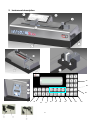
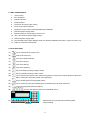
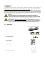
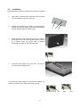
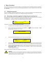
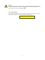
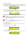
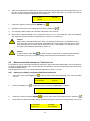
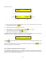
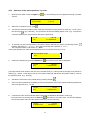
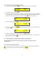
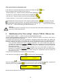
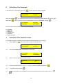
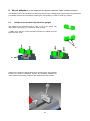
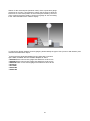
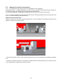
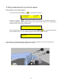
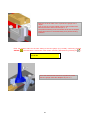
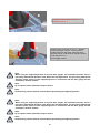
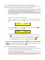
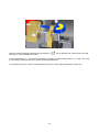
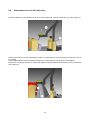
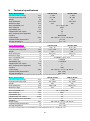
1 2 Index 1 Safety regulations .................................................................................................................................... 4 1.1 Important information ............................................................................................................................ 1.2 Safety symbols.. .................................................................................................................................... 1.3 General warnings .................................................................................................................................. 2 Instrument description ................................................................................................................................ 5 2.1 Instrument ........................................................................................................................................... 6 2.2 Display ......................................................................................................................................………... 3 Getting started .......................................................................................................................................... 7 3.1 Setting up ............................................................................................................................... …………. 3.2 Packing list ......................................................................................................................................... … 3.3 Installation .................................................................................................................................... ……8 4 Basic Functions ........................................................................................................................................ 9 4.1 Putting into operation ............................................................................................................................ 4.2 Zero setting ........................................................................................................................................ … 4.3 Internal measurements ..................................................................................................................... 11 4.4 External measurement ................................................................................................................... ...11 Measurement with tolerances / positions list ................................................................................. ..12 4.6 Movement with manual steps / automatic ..............................................................................……….15 5 Modification of the ″Zero setting″ ( only for Tar-AL 3 micron accuracy ) ............................................ 16 6 Selection of the language ..................................................................................................................... .18 7 Selection of the mm/inch mode .................................................................................................. ..…….18 8 Use of adaptors ...................................................................................................................................... 20 8.1 Adaptors for standard 2-point bore gauges .................................................................................. ….20 8.2 Adaptors for external micrometers .................................................................................................. ..21 8.3 Special supporting block for 3-point bore gauges ............................................................................ .23 8.4 Adapters for bar caliper .................................................................................................................... .28 8.5 Adapters blocks for 2-point internal micrometer .............................................................................. .29 8.6 Adapter for 2-points small precision bore gauges ............................................................................. 30 8.7 Attachments for dial indicators ......................................................................................................... .31 8.8 Attachments for level dial indicators................................................................................................. .33 9 Technical specifications ...................................................................................................................... ..34 10 Warnings for correct use………………………………………………………………………………… .......35 10.1 Cleaning…………………………………………………………………………………………………… ... 10.2 Complaints / Repairs ...............................................................................................................……… 11 Declaration of conformity. …………………………………………………………………………...….….....36 3 1 Safety regulations 1.1 Important information In order to prevent any damages due to a wrong manipulation, please read carefully the following instructions. GV METROLOGIA will not assume any responsibility in case of damages caused by inadequate use which is not in line with the present manual. 1.2 Safety symbols The following safety symbols are used in this manual: General warning, utilization advices Risk of electric shock Electrostatic protection 1.3 General warnings Protection against electrostatic interferences: The static electricity can damage the electronic components of the instrument. In order to prevent this type of damages, avoid any contact with the connector pins. In order to prevent any changes of the instrument performance or any accident, the instrument should never be dismounted. In case of problems with the instrument or any parts, switch off the instrument immediately and disconnect the power supply. Please contact your local TRIMOS agent. This instrument incorporates high voltage components. If, for any reason, the instrument needs to be opened, only authorized personnel is allowed to do it. 4 2 Instrument description 27 26 25 14 15 16 17 5 18 19 20 21 22 23 24 2.1 UNIT COMPONENTS: 1 ) outer casing 2 ) PLC keyboard 3 ) mobile reference 4 ) fixed reference 5 ) screws for anchoring outer casing 6 ) base mount made of granite 7 ) guide pins for the correct centring/positioning of adapters 8 ) electrical power supply switch 9 ) RS232 socket for connecting the unit to a PC 10 ) 18V – DC electrical power supply socket 11 ) electrical power supply cable 12 ) AC electrical power supply adapter (input AC 100/240V 50/60Hz 130/170VA- output DC 18V 4.7A) 13 ) cable for connection to electricity 2.2 PLC FEATURES: 14) key for entering function keys menu 15) scroll to sub-menu key 16) move arrow downwards key 17) move arrow up key 18) move arrow left key 19) move arrow right key 20) key for manually scrolling to higher values 21) key for manually scrolling to lower values 22) key for returning to previous menu, allows the operator to exit from the various functions. When the slide is moving it controls the halting of the slide itself. 23) key for inserting and correcting table values 24) key for confirming value just entered (does not activate any instrument functions) 25) key for cancelling last character entered 26) 27) keys for activating functions in the individual menus alphanumeric area of keyboard for entering data (area outlined) 6 3 Getting started 3.1 Setting up The packing consists in two boxes, an internal and an external one. The latter is used to separate the instrument from the accessories. Once the external box opened, take out the accessories and the internal box. Unscrew the lateral screws located at the base of the box and lift the external box. Don’t remove the screws on the bottom part of the transportation pallet. Now you have in front of you the instrument wrapped in its plastic protection against humidity. After stabilizing the instrument to ambient temperature, open the plastic protection. Position the pallet on a stable surface, able to support the instrument’s weight, unscrew the 4 screws fixing the pallet to the instrument. It is now possible to position the instrument in the desired position. Warning When unscrewing the 4 screws fixing the base of the instrument to the pallet, the instrument will become free from the pallet, therefore it is important to position yourself on a solid and stable table in order to prevent any dangerous and unplanned movement of the instrument. Warning When unpacking, don’t open the plastic protection, but leave the instrument in its packing at ambient temperature for some time to allow it to stabilize : if the instrument was at temperatures below 10 °C, it is better to wait a few hours before opening the plastic protection in order to prevent any risk of condensation. 3.2 Packing list The standard supply of the instrument includes the following items: 1. Instrument TAR-AL 2. AC adaptor with power supply cable 3. Anti vibration pads 4. User’s manual 5. Test certificate 6. Certificate of guarantee 7 3.3 Installation Immediately after unpacking, prepare the instrument as follows: 1. After having removed the accessories from the upper box in the packing, open the lower box. 2. Position the instrument on a table or on a flat surface capable to accept the weight of the instrument (50 kg for TAR-AL 300 and 75kg for TAR-AL 500). 3. Raise the base of the instrument and tilt it in order to reach bellow, fix the three anti vibration pads (A central, B, C lateral) under the granite base, re-position horizontally the TAR-AL and adjust the pads. 4. Connect the AC adaptor (11) to the 18V – DC plug on the back of the instrument (10). A B C 5. Connect the power supply (13-A) to the AC adaptor (12) and then connect it to the main power supply (13-B). 12 8 13-B 13-A 4 Basic Functions The TAR-AL instrument can be used for setting of internal and external comparative measuring equipment. For each type of instrument, you have to use the appropriate adaptor in order to optimize the use of the TARAL instrument. 4.1 Putting into operation Once the installation finished as described under section 3.3, switch the instrument on by pressing the on/off switch (8). The instrument is now ready for zero setting and starting measurements. 4.2 Zero setting ( operation suggested 3-4 times along the working day ). After turning the instrument on, you will have access to the following menu: on the upper line you can read the last position (e.g.: 42.159), on the lower line in alternation the following selection: “F1=EXECUTE F2=ZERO A” and the text “ZERO SETTING X NOT DONE”. 42.159 42.159 ZERO SET. X NOT DONE Therefore it is necessary to perform the first zero setting: 1 If needed, remove the adaptor remaining on the fixed support 2 Press on the main menu the function key F2=ZERO A (26) IN PROCESS” will appear on the screen. . During this operation “ZERO ZERO IN PROCESS 3 At the end of the zero setting the screen returns to the main menu. 42.159 F1=EXECUTE 42.159 F2=ZERO A 4 At the end of the zero setting, position the certified instrument (with 1 micron resolution) on the known nominal value of the master ring and verify if the nominal position of the instrument is equal. 5 Only for models TAR-AL 3 Micron line: In case of a difference between those two values, follow the procedure described under the section. For procedure of TAR-AL S line contact the GV METROLOGIA agent. “ 5) Zero reference correction “ At the end of the above procedure, the instrument is operational. Warning During the first start-up of the instrument, because of possible movements during transportation, we recommend to verify the absolute position of the measuring attachments using a master or measuring instrument in excellent condition. 9 Warning During the first start-up of the instrument, because of possible movements during transportation, we recommend to position the mobile measuring attachment at a distance of about 100 mm from the fixed one by using the following key ( ) 4.2.1 Mode Stand-by The instrument will automatically switch to ″Stand-by″ mode after 10 minutes if not in use. The display will show ″Stand-by″. To re-activate all functions, press any key. Stand-by 10 4.3 1. Internal measurements After the initial zero setting as described under section 4.1., and before any other operation, remove the adaptor (if any) mounted on the instrument, then enter directly the required nominal dimension into the main menu, in [mm] (ex.: 158.235 ). This value is displayed on the left side of the screen. The value of the previous position is shown on the right. (ex.: 15.000): 158.235 F1=EXECUTE 15.000 F2=ZERO A 2. Confirm the entered value by pressing the ENTER (24) key. 3. After having removed the installed adaptor (if any), activate the displacement of the mobile measuring attachment by pressing F1 (26) . After a few seconds, the mobile part positions itself to the indicated value, and the new position value will be displayed on the top right side: 158.235 F1=EXECUTE 4. 158.235 F2=ZERO A Now insert the adaptor for the instrument to be calibrated and perform the setting. If a new positioning is required, remove the adaptor and repeat the above procedure as described in section (1). Caution When using a motorized instrument, which can generate a high force, it is important never to force along the measuring axis during the displacement of the mobile part to avoid any positioning error, in which case an alarm will occur. If this happens, you will have to perform a zero setting as described under section 4.2. Caution In case of alarm, press ESC ( ) in order to stop the instrument (or switch off and restart the instrument), then carry out a zero setting as described in section 4.2. 4.4 External measurements 1. After the initial zero setting and before any other operation, remove the adaptor (if any) mounted on the fixed measuring attachment. 2. Open the first sub-menu by pressing key PgDw (15) 3. 4 functions are at your disposal: F1) EXTERNAL F3) OFFSET . F2)PARAM. F4)TOL. 4. Select F1) EXTERNAL (26) 5. Two lines of text are displayed : at the top, the current external position of the instrument (e.g.: 25.360) X = 25.360 Q= external 11 6. Enter the required external dimension in [mm] by using the alphanumeric part of the keyboard (27). The text “Q=” on the lower line disappears and the entered value will be displayed (e.g.: 50.250). The value of the current external position is displayed on the first line. X = 25.360 50.250 external 7. Confirm the input by pressing the key ENTER ( 24 ) . 8. Activate the movement of the mobile part by pressing F1 (key 26) 9. The carriage positions itself to the indicated value after a few seconds. . 10. Now insert the specific adaptor for the instrument to be set. For a new positioning, remove the adaptor and repeat the above procedure as described from section (1) to section (4). Caution When using a motorized instrument, which can generate a high force, it is important never to force along the measuring axis during the displacement of the mobile measuring part to avoid any positioning error, in which case an alarm will occur. If this happens, you will have to carry out again a zero setting as described in section 4.1. Caution In case of alarm, press ESC ( ) in order to stop the instrument (or switch off and restart the instrument), then carry out a zero setting of the instrument as described in section 4.2. 4.5 Measurement with tolerances / Positions List It is possible to set up 100 values with/without tolerances, called "ARTICLE/ITEM CODE", and to recall them by entering an alphanumeric code or by scrolling the memorized list. The unit is delivered from the factory with a number of default values. Internal positions are from I 1 to I 60 and External positions are from E 1 to E40. 4.5.1 Setting (or editing) positions with/without tolerances 1. In the main menu, press PgDw (15) choices: in order to have access to the following menu, with 4 possible F1) EXTERNAL F3) OFFSET 2. Press F2) PARAM ( 26 ) F2) PARAM. F4) TOL. . A password must be entered “PASSWORD”: “123456 “. PASSWORD 3. Confirm the value by pressing ENTER , you have now access to the following menu. Select F4) 4. Select EDIT F1) and the following display appears showing the parameters corresponding to the one of F1)Q.ZERO F3) mm /in F2)LANG. F4) TAB/OFF 12 the stored article code *: a F1) EDIT T. F3) OFFSET F2) RS232 E23 FROM 0.000 Q = 10.000 TO 0.030 c b d * To select a position from the list for saving/ editing ( I1-E40 ) , use the scrolling function by using the upwards /downwards arrows ( / ). 5. Once positioned on the desired value i.e. E23, then Insert ( overwriting ) a new nominal/position value + ENTER Digit ( Optional ) Lower tolerance + ENTER (e.g.: 0) Digit ( Optional ) Upper tolerance + ENTER (e.g.: 0.050) (e.g.: 11.000) (The values introduced are displayed at the same time). Now the display appears as follow ( in this case E means that the value of 11.000 refers to the External side of the ceramic pads: E23 from 0.000 Q = 11.000 to 0.050 Press ESC and confirm the storage of the new entered values by simultaneously pressing “SHIFT” and “Y” ( ). + Once the new value has been entered, you are able to add/edit more positions. Press the ( scroll the list and position on the new position. / ) key to 4.5.2 Entering of values with tolerances using a PC As an alternative to manual input of values, it is possible to enter 100 values with tolerances by using a computer connected through the RS232 port at the rear of the instrument. To perform such a procedure, it is necessary to use an optional program available on CD. 13 4.5.3 Selection of the preset positions by code. 1. Open the main menu. Press the PgDw (15) choices: key. The following sub-menu appears showing 4 possible F1) EXTERNAL F3) OFFSET F2) PARAM. F4) TOL. 2. Select the command F4) TOL. (26) 3. The first line shows the position value of the last measurement with tolerances used (e.g.:111.08 ), then the current position (e.g.:158.235 ). The second line shows the related position code (e.g.: I33) and the command F1 has to be pressed to execute the positioning : 111.08 I 33 158.235 F1=EXECUTE 4. To execute any other saved position just insert the article code that you wish to use pressing SHIFT together with button « I » or « E » ; then digit the number of the position i.e. « 14 ». The complete position code will be i.e. « E14 ». During this operation the value will be displayed on the second line at left (e.g.: E14). REFERENCE CODE E14 5. Confirm the selection by pressing ENTER (24) , the previous menu will be displayed : 111.08 E14 158.235 F1=EXECUTE (The real position value results of the sum of the nominal value (e.g.: 85mm) and the average of the tolerance values (e.g.: +0.000; +0.030 equal +0.015). The mobile measuring attachment will position itself at a half of the tolerance value. (e.g.: 85.015)). 6. Activate the movement of the mobile part by pressing F1 (26) 7. At the end of the positioning, the display shows the new position value of the mobile measuring attachment at the top right side (e.g.: 111.08) 111.08 E14 8. . 111.08 F1=EXECUTE A new article code can be selected and the procedure repeated as described in section (4) Close the menu by pressing twice the ESC (22) and return to the main menu. The first line displays the current position value and the entered value (e.g.: 85.015 / 85.015) : 111.08 F1=EXECUTE 111.08 F2=ZERO A 14 4.5.4 Selection from the list with scroll function. 1. In the main menu, press PgDw (15) to have access to next menu, which offers 4 choises : F1) EXTERNAL F3) OFFSET F2)PARAM. F4)TOL. 2. Select command F4) TOL./TAB (26) . 3. A menu opens, showing on the first line the positioning value of the last measurement with tolerances (e.g.:85.015), then the current position (ex.:158.235). On the second line, the designation of the value with tolerances (article code) last used (ex.: I8) and command F1 85.015 I8 4. When pressing DOWN ARROW ( 158.235 F1=EXECUTE ), you enable the scroll function. I9 from -0.000 5. With the up/downwards arrows ( by pressing F1 to execute a positioning : / Q = 85.000 to 0.030 ), select the requested article code (i.e. I10 ) and confirm choice . 55.012 I55 200.000 F1=EXECUTE 6. Activate the movement of the mobile part by pressing F1 7. In order to select a new value with tolerances proceed as described in point (4-6). To exit this automatic mode press two times ESC (22) ( 4.6 X 2 TIMES. ). Movement with a constant steps ( manual and automatic ). It is possible to perform a positioning of the mobile part having constant steps in manual or automatic mode. 4.6.1 Input of steps in manual mode Enter the required step in the main menu (e.g.: 0.015) and confirm the value by pressing the ENTER (24) ( ) key. Activate the mobile movement by pressing the keys ( 15 / ). 4.6.2 Input of steps in automatic mode In the main menu, press simultaneously the “SHIFT” and “right arrow” ( Enter the following values by observing the sequence: + ) keys. - Number of steps (e.g.: 10) and confirm by pressing the key ENTER (24) ( - First step (e.g.: 20) and confirm by pressing the key ENTER (24) ( ) ) - Last step (e.g.: 100) and confirm by pressing the key ENTER (24) ( ) - Length of steps (e.g.: 5) and confirm by pressing the key ENTER (24) ( Check whether the entered values are correct using the up/down arrows ( ) / ) and press ESC (22) ( ) to activate the mobile movement. The mobile measuring attachment will move automatically to each defined step with a stop of about 3 sec. at each step (e.g.: 20 – 25 – 30 – 35 - …..- 100 for the first cycle and e.g.: 100 – 95 - …- 20 for the second cycle until the last step n° 10. Warning For a normal operation in automatic mode you must select step values which correspond with the range of the measuring instrument. 5 Modification of the ″Zero setting″ - Only for TAR-AL 3 Micron Line. * For zero setting of TAR-AL 1. , please contact your GV METROLOGIA agent. The zero setting modification must to be done whenever a difference between a measuring value using a master and the instrument will be detected. To check the zero point use a two point bore gauge in excellent condition and a master ring. Position the instrument to the nominal value of the master ring (e.g. 50.003) and verify using a two point bore gauge, previously calibrated. If a difference will be detected, perform a modification of the zero (preset) as follows: - If the instrument measurement value is higher compared to one of the master ring gauge (e.g.: +0.008mm) it is necessary to increase the zero position of the instrument at the same value amount (e.g.: from the current position of 30000 to 30008, taking into consideration that these values are expressed in microns) - If the instrument measurement value is lower compared to the one of the master ring gauge (e.g.: 0.008mm) it is necessary to decrease the zero position of the instrument at the same value amount (e.g.: from the current position of 30000 to 29992, taking into consideration that these values are expressed in microns) The input of the calculated value must be performed as follows: In the main menu, press the key PgDw (2) , the first sub-menu will be displayed: F1) EXTERNAL F3) OFFSET Select F2) PARAM F2) PARAM F4) TOL. . In order to access the next sub-menu enter the following password (123456) and confirm by pressing the key ENTER . In the new sub-menu select F1)Q.ZERO ( F1)Q.ZERO F3)mm/in F2)LANG. F4)TAB/OFF Now the new zero position can be entered. 16 ) Caution Before modifying the zero value, it is advised to write down the actual existing value. The value displayed on the second line indicates the actual zero position value (e.g.: 30000). 01) POSITION OF ZERO X= 30000 The modification done, press the key ENTER press the key ESC “Y” ( + in order to confirm the entered value. To exit this menu . Confirm the storage of the entered value by pressing simultaneously the “SHIFT” and ) keys. Press ESC ( ) to return to the main menu. Caution After each modification of these parameters, the zero must be performed following the procedure described in point 4.2. After each modification of the zero point check the result using a master ring gauge. Caution The correct functioning of the instrument depends on the zero position. We advise to check the zero position periodically. As this is a delicate operation it is recommend that it will be carried out by a qualified person. Caution The zero setting was carried out in temperature conditions of 20 0.5C and relative humidity of 50% 5%. Therefore, if the instrument is used under other workshop temperature conditions, it is important to let the instrument stabilize during 24 hours and carry out a new zero correction. Caution For calculation of reference conditions, the instrument is subject to an expansion factor of 11.5m / per °C / m (similar to steel). 17 6 Selection of the language In the main menu, press the key PgDw (2) ( ). The first sub-menu will be displayed: F1) EXTERNAL F3) OFFSET Select F2) PARAM ( with ENTER ( F2) PARAM F4) TOL. ) to access the second sub-menu. A password (123456) must be entered. Confirm ). In the next menu which will be displayed select F2)LANGUAGE (key 26) ( F1) Q.ZERO F3) mm/in ) F2)LANG. F4)TAB/OFF Enter the value which corresponds to the required language: 0 1 2 3 4 5 = ITALIAN = ENGLISH = FRENCH = ESPAGNOLE = GERMAN = PORTUGUESE 7 Selection of the mm/inch mode Il is possible to perform measurements using different measuring units ( [mm] or [inch]): 7.1 Select PgDw (2) ( ) in the main menu to enter the first sub-menu: F1) EXTERNAL F3) OFFSET 7.2 F2) PARAM F4) TOL. Press F2) PARAMETERS. The submenu is now open: F1)Q.ZERO F3)mm/in 7.3 F2)LANG. F4)TAB/OFF Select F3) mm/in and the scale menu is open: 31) mill = 0 X= inch =1 0 7.4 Enter the required value ( 0 = [mm] , 1 = [inch] ). Confirm by pressing ENTER (24) ( ). 7.5 To exit the menu press ESC ( 7.6 Confirm the storage of the modification by pressing simultaneously the keys “SHIFT” and “Y” ( ). ). 18 + The corresponding parameter of the required measuring unit will be displayed and must be selected.Press ESC ( 7.6 ) to return to the main menu. Turn OFF then ON the machine and Redo the zero setting of the machine pressing F2 ( 19 ) 2 times. 8 Use of adapters ( on the manual just most popular instruments, further available by request ). The adaptors have to be mounted only after the positioning (zero setting) of the mobile measuring attachment. The adaptor must be removed before selecting any new position, in order to avoid any collision. 8.1 Adapters for standard 2-point bore gauges The adaptors are positioned until its stop on top of the pivots (30) observing the openings (31). Press them down strongly. ** (Make sure that the contact surfaces between the adaptor and the instrument are clean ) 31 30 Position the 2-point bore gauge between the centring faces, press slightly towards the ceramics measuring surface. By swivelling establish the contact with the measuring surface of the mobile part at the left side. 20 Search for the reversal point (minimum value). If the 2-point bore gauge movement is too fast, it is important to wait a few seconds to allow the instrument to correct the position of the mobile part caused by the force of the 2-point bore gauge setting. Set the bore gauge to zero according to the value indicated on the TAR-AL display. To request any further adaptors for bore gauges, please identify the type of foot ( round or with wheels ) and measure the width with a caliper. * In the picture the dedicated adapter for bore gage with a one-size space width; available also the versatile adaptors AL Serie: - AL30055 which covers a bore gauge foot width from 30 to 55 mm - AL55090 which covers a bore gauge foot width from 55 to 90 mm - AL900125 which covers a bore gauge foot width from 55 to 90 mm - AL125170 - AL170220 - AL220-280 - AL280-350 21 8.2 Adaptors for external micrometers 8.2.1 For dimensions below 100 mm the use of the adapters is not suggested. Standard procedure : 1 adapter positioned in one side ( left or right side is discretional ) and the reaching of the minimum value in the opposite side by sliding the micrometer surface. The use of both adapters is suggested for dimensions above 150 mm or for heavy micrometers. 8.2.2 Position the adaptors for external micrometers onto the measuring attachments of the instrument until they are in contact with the measuring surfaces. Mobile measuring attachments : Slide the V-block over the mobile measuring attachment (1), push it against the measuring surface (2) and tighten the knob (3) to fix the accessory. - Clean the micrometer contact- surface of the anvils which have to have the planarity not modifies by the daily use. - Position the external micrometer on top of the V-shaped locations and the searching for the minimum value in the opposite side by sliding the micrometer surface. 22 8.3 Special supporting block for 3-point bore gauges Set the TAR-AL for the 3-point adapters. In the main menu, press Pg/Dw (15) ( ) to open following sub-menu F1) EXTERNAL F3) OFFSET F2) PARAM. F4) TOL. Activate F3) OFFSET ( ). The display is ready for the input of the designation (Article-no./ ″ARTIKEL NUMBER″). This designation defines the required Preset value of the corresponding supporting blocks to the TAR-AL displacement. ARTICLE NUMBER 1 Enter the required article-nr. (e.g. 1) and confirm by pressing ENTER ( ). The actual position related to the entered article-nr. of the 3-point bore gauge will be displayed e.g. 100.000) X=100.000 Q= 1 The TAR-AL is now working in diameter. Position the “V” adapter vertically on top of the 2 fixed pins and press until it stops (1) und fix it by tightening the two screws (2). 23 Measure the anvil width of the 3-points bore gauge with a caliper. Then chose the counter-adapter with the space width of the same dimensions and mount it as per nr. 3. The perfect matching of the micrometer anvil and the adapter shape will ensure no horizontal sliding for a perfect zeroing operation. Enter the required value for the zero setting of the bore gauge (e.g. 50.000), confirm by pressing ENTER ( ) and activate the movement of the mobile measuring attachment by pressing F1( X=100.000 Q=50.000 1 Once the diametral dimensions is reproduced, insert the bore gauge inside the adapters as per nr. 4 24 ). Position firt the 2 anvils on the « V » adapter as per nr. 5 Keeping the 2 anvils still on the « V » adapter, swing vertically the anvil in contact with the mobile reference and at the same time open the friction drive until the anvil reaches ceramic pa as per point nr. 6 Do not apply a force. Note: When using the supporting blocks for 3-point bore gauges, the instrument must be set to a previously determined deviation value before the first application. The previously determined deviation value, proper to each supporting block in connection with the bore gauge and the instrument, must be entered. Note: Up to 5 preset values (deviation) may be stored. Note: All measuring surface must be cleaned before positioning the supporting blocks. Note: When using the supporting blocks for 3-point bore gauges, the instrument must be set to a previously determined deviation value before the first application. The previously determined deviation value, proper to each supporting block in connection with the bore gauge and the instrument, must be entered. Note: Up to 5 preset values (deviation) may be stored. Note: All measuring surface must be cleaned before positioning the supporting blocks. 25 8.3.1 Calculation and input of the offset ( preset ) value of a supporting block. Set the 3-point bore gauges to the value of the supplied master ring (e.g. 50.000) and prepare the TAR-AL instrument to be able to perform the checking procedure. Star up from the main menu: 1 2 The supporting block is in position. Keep two contact points of the bore gauges in contact with the V of the supporting block. Move the mobile measuring attachment manually (keep the key pressed) towards the third contact point of the bore gauge at a distance of approx. 3mm. The value reached, stop the mobile part. Establish contact of all three contact point of the bore gauges with the measuring surfaces of the measuring attachments using the friction drive. Determine, to which diameter value the position of the mobile part can be assigned to (value shown on the 3-point bore gauge). 3 The offset value to be stored will be calculated as follows: OFFSET = (linear value, shown on the TAR-AL display) – (value of the 3-point bore gauge x 1.5) 4 Storing of the calculated offset value: select PgDw (2) in the main menu to open the first submenu: F1) AUSSEN F3) OFFSET 5 Select F2) PARAM ( F2) PARAM F4) TOL. ), enter the code (123456) and confirm by pressing the ENTER ( In the following menu, activate F4) TAB/OFF ( F1)Q.ZERO F3) mm/in 6 ) key. ). F2) LANG. F4) TAB/OFF In the following open menu enter the following by observing the sequence: - the ″Article-nr." which refers to the accessory used (e.g.: 1) – confirm by pressing ENTER - ( ) the value of the coefficient ″m″ mentioned on the supporting block (e.g.: 1.500005, always mentioned with 6 digits after the decimal point) – confirm by pressing ENTER ( - the calculated offset value “Q” (e.g.: -12.428) - confirm by pressing ENTER ( ) ) If other offset value must be entered and stored, activate the ( ) (16) key and enter other parameters corresponding to other supporting blocks as described in point 6. If not, exit the menu by pressing the ESC ( ) key. Confirm the storage of the entered parameter by simultaneously pressing the “SHIFT” and “Y ” ( + 8.3.2 ) keys. Return to the main menu by pressing ESC ( ). Checking and modification of the offset value for 3-point measurements 1 Set the 3-point bore gauge using a corresponding master ring. Set the TAR-AL instrument to the same value (e.g. 50.000mm) und perform a comparative measurement. 2 If a difference between the two values will be detected, a modification of the stored offset (**) value in the TAR-AL instrument must be performed. The necessary correction value must be calculated: the already stored offset value (e.g. -12.428) is taken into consideration. The correction value is calculated as difference between the value stored in theTAR-AL instrument and the one mentioned on the 3-point bore gauge x 1.5. 26 * Example: the 3 - point bore gauge showed a measuring value of 50.030 in comparison to the one of 50.000mm stored in the instrument. A modification of the offset value must be as follows: (50.000 – 50.030) x 1.5 = -0.045mm The new offset value to be stored is as follows: Q = -12.428 – 0.045 = - 12.473. * Is the indicated value of the 3-point bore gauges smaller (e.g. 49.970mm) as the one stored in the instrument, the modification will be calculated as follows: (50.000 – 49.970) x 1.5 = +0.045mm. The new offset value is as follows: Q = -12.428 + 0.045 = -12.383 3 Enter the new offset value as described in article 8.3.1 (point 4 and 5). Select the parameter to be modified in the table by pressing the ( ) key. Enter the value as described in point -6-. Note For practical reasons, it is recommended to observe a max. distance of 1mm between the measuring surface at the mobile measuring attachment (left) and the one of the 3-point bore gauge when performing a calibration. The calculation will be done as described above. 27 8.4 V-shaped supporting blocks for internal and external comparative measuring equipment ( bar calipers ). This kind of comparative measuring equipment may be positioned as shown below (the anvils of the measuring arms are set on top of the measuring surface of the two measuring attachments). A required preset value has been entered previously to perform the displacement of the mobile part. To be able to position other types of measuring anvils, V-shaped supporting blocks are available, see picture shown below. - One V-shaped block will be placed on top of the attachment (one side) and fixed by tightening the screws. - The second V-shaped block (optional) will be placed on top of the mobile measuring attachment and fixed by tightening the knob. - For zeroing, position the left/right side of the instrument in on the adapter and in contact with the ceramic (5 , 6 ) and check the minimum value on the opposite side. - For External comparative zeroing, position the adapters in contact with the external ceramic surface. - The use of a second adapter is discretional and according to the type of instrument. 28 8.5 Supporting blocks for 2-point internal micrometer Position the supporting block on top of the mobile measuring attachment (1). Slide the block to the left side until it is in contact with the measuring surface or adjusted according to the anvil width (2) and fix it by tightening the knob (3). Position the measuring anvil (4) of the bore gauge on top of the V-shaped location of the block (5). Determine the reversal point (open slightly the internal micrometer). 29 8.6 Attachments for cylindrical contact meas. Surfaces (2-points precision bore gauges). Position the holder before setting the required value (1) and fix it by tightening the screws (2). Insert the bore gauge to be checked and set: Set the mobile part to the required value. Position the bore gauge (7, 8). Adjust the required measuring height (loosen knob (9), adjust the support and tighten the knob again). Determine the reversal point by swivelling slightly the bore gauge (10 + 11). 1 2 1 7 1 3 8 4 9 5 6 6 30 8.7 Attachments for dial indicators N.B. reversed picture. Position holder and stop attachment ( 1 + 2 ) and of the mobile measuring attachment ( 3 + 4 ). Same procedure for lever comparator instruments, see point 8.9 Insert the dial indicator into the location of the right side holder ( 5 ). 31 Move the mobile measuring attachment by pressing the ( indicator ( 6 ) and establish the contact. ) key to approach the contact point of the dial Fix the dial indicator ( 7 ) , and zeroing the indicator manually in a determined position i.e. 17.000 ; then start the checking by displacement of the mobile measuring attachment. It is possible to perform a series of measurements having the same step as described in article 4.6. 32 8.8 Attachments for level dial indicators Position holder and contact attachment as shown at the right side. Lock the mobile arm (1) of the holder "(2). Position the lower pin (3) of the attachment A30001 in contact with the ceramic surface and tight the screw of the adapter. The level dial indicator must be installed so that it is in contact with the higher pin (4) of the adapter. Perform the checking procedure by moving the mobile measuring attachment according to the required step (see article 4.6). 33 9. Technical specifications Metric Specifications Internal measuring range External measuring range Weight Base dimensions Maximum height Max. permissible error Max. resolution Repeatability (2s) Displacement max. speed Max. measuring force applicable Interface Power Supply Operational temperature limit Storage temperature TAR-AL S300 TAR-AL S500 1 - 305 1 - 505 40 - 325 40 - 525 50 75 610 x 300 820 x 300 270 300 1,5 + L(mm) / 300 0.001 <1 50 2 RS232/USB 100 / 240 AC – 1.5 A – 50 / 60 Hz +10..+40 +10…+40 mm mm kg mm mm m mm m mm/s N VAC °C °C The values of max. permissible error and repeatability are valid at temperature of 20 0.5 °C and relative humidity of 50 5%. U.S.A. Specifications Internal measuring range External measuring range Weight Base dimensions Maximum height Max. permissible error Max. resolution Repeatability (2s) Displacement max. speed Max. measuring force applicable Interface Power Supply Operational temperature limit Storage temperature TAR-AL S300 TAR-AL S500 0.04 - 12 0.04 – 20 1.57 – 13.5 1.57 - 21 110 165 24 x 11.8 32 x 11.8 10.6 11.8 0.000060 + L(in) / 11.8 0.000020 < 0.000040 2 2 USB 100 / 240 AC – 1.5 A – 50 / 60 Hz 50F…104F 50F…104F in mm lbs in in in in in in/s N VAC F F F The values of max. permissible error and repeatability are valid at temperature of 20 0.5 °C and relative humidity of 50 5%. Metric Specifications Internal measuring range External measuring range Weight Base dimensions Maximum height Max. permissible error Max. resolution Repeatability (2s) Displacement max. speed Max. measuring force applicable Interface Power Supply Operational temperature limit Storage temperature TAR-AL S1000 TAR-AL S1500 1 - 305 1 - 1500 25 - 1040 25 - 1540 254 419 1330 x 300 2255 x 277 340 354 1,5 + L(mm) / 300 0.001 <1 50 2 USB 100 / 240 AC – 1.5 A – 50 / 60 Hz +10..+40 +10…+40 mm mm kg mm mm m mm m mm/s N VAC °C °C The value of max permissible error and repeatability are valid at temperature 20°± 0,5°, humidity 50% ± 5% 34 U.S.A. Specifications Internal measuring range External measuring range Weight Base dimensions Maximum height Max. permissible error Max. resolution Repeatability (2s) Displacement max. speed Max. measuring force applicable Interface Power Supply Operational temperature limit Storage temperature TAR-AL S1000 TAR-AL S1500 1 - 40 1 - 60 1.57 – 41 1.57 - 61 451 705 52 x 11.8 89 x 11.8 14 14 0.000060 + L(in) / 11.8 0.000020 < 0.000040 2 2 USB 100 / 240 AC – 1.5 A – 50 / 60 Hz 50F…104F 50F…104F in mm lbs in in in in in in/s N VAC F F F The value of max permissible error and repeatability are valid at temperature 20°± 0,5°, humidity 50% ± 5% 10 Warnings for correct use Caution This instrument cannot automatically check its own position (for example, by taking the zero with the two probes). Therefore, we recommend a periodic checking of the zero point position using a master ring gauge and a 2-point bore gauge of extreme good conditions. Caution The manufacturer reserves the right to modify the instrument without prior notice. 2.1 Cleaning Synthetic parts, display unit, as well as the painted parts of the instrument can be cleaned with a lightly damp cloth. Dirty can cause measurement error: it’s recommended to keep the ceramic pads clean. 2.2 Complaints / Repairs In case of problems, please contact your GV METROLOGIA agent. Use original packing for transport. The guarantee is valid only if checked by your GV METROLOGIA agent. 35 9 DECLARATION OF CONFORMITY GV METROLOGIA hereby declares that the pre-setting units TAR-AL S300 TAR-AL S500 TAR-AL S1000 TAR-AL S1500 are in conformity with the following regulations: EC Directive 89 / 336 / EC EN61326-1 + A1 2.2.1.1.1.1..1 EN61000-3-2 EN61000-3-3 + A1 6. EN61000-4-2 + A1 + A1 + A2 EN61000-4-3 EN61000-4-4 + A1 + A2 EN61000-4-5 + A1 EN61000-4-6 + A1 EN61000-4-11 + A1 GV Metrologia Tel.: 051 6870801 Via Sabin , 5 40017 San Giovanni in Persiceto (BO) Italia Fax.: 051 6870850 [email protected] 36