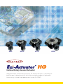
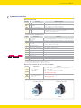
1
Hollow Rotary Geared Actuator
Hollow Rotary Index Table
Accurate Gear Driven
High Precision
High Rigidity
High Torque
Easy to Use
HG60
HG100
HG130
HG200
Hollow Rotary Geared Actuator
High performance of Hollow Rotary Actuator, Ezi-Actuator HG Series, is extremely low
backlash gear is driven directly into the hollow rotary table combines to high speed,
high accuracy of closed loop stepping control system, Ezi-SERVO
HOLLOW ROTARY TABLE
Large Diameter hollow bore to penetrate the output table equipped HG Series ensure
flexibility and convenience in the design of equipment when install complex wiring and piping.
Ø75mm
□200mm
ex) only HG275 series
Model Name
HG60
HG100
HG130
HG200
HG275
Size of plinth (Frame Size)
60mm
100mm
130mm
200mm
200mm
Hollow Bore Diameter
20mm
29mm
40mm
40mm
75mm
ACCURATE GEAR DRIVEN
Extremely low backlash gear direct drive, so that repetitive positioning accuracy from a
single direction is ±15sec, lost motion by positioning from two directions for less than
2min. and the precise positioning can be determined. And Belt and Pulley are not used in
this system so it enables cost saving, unnecessary of maintenance and repair service
without adjustment of belt-tensioning
HG275
HIGH RIGIDITY
High rigidity of taper roller bearing and Ball Bearing integrated HG Series maximizes
allowable thrust load and moment load ( But, Deep Groove ball bearings applied in
HG60 Series )
Output Table
Ball Bearing
Taper Roller
Bearing
Taper Roller Bearing
Ball Bearing
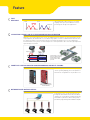
Feature
FAST
RESPONSE
Speed
Speed
Settling Time
Time
High rigidity Rotary table fixed to the closed loop
stepping control system, Ezi-SERVO can shorten
positioning time for big inertia applications.
Time
SUPPORTING SUDDEN LOAD FLUCTUATION AND RAPID ACCELERATION
Adopting a closed loop stepping control system, Ezi-SERVO designed to maintain synchronism and does not have
step-out problem, Ezi-Actuator HG series can be driven by rapid acceleration or sudden load fluctuation because
the situation in a typical servo system that is prone to fluctuation, Hunting does not occur. For sudden load
fluctuatoin with a servo system is essential to improve the control performance does not need to gain adjustment
is gain Tuning Free Actuator.
Complete stop
Hunting
Load variations are concerned
about the equipment without
having to adjust the gain,
HG Series enables stable
operation.
VARIETY OF CONTROLLER WITH HIGH PERFORMANCE AND MULTI-TASKING
Ezi-SERVO, high performance closed loop stepping
control system by adopting, pulse train input drives
and controller integrated drives are possible to use.
Pulse Input drive
Controller Embedded Drive
(Enable to operate Multi-Axes
based on Network)
NETWORK BASED MOTION CONTROL
PC
A maximum of 16 axis can be operated from a PC
through RS-485 communications. All of the Motion
conditions are set through the network and saved in
Flash ROM as a parameter. Motion Library (DLL) is
provided for programming under Windows 2000/XP.
Ezi-Actuator HG _ 4
/5
POSITION TABLE FUNCTION
Position Table can be used for motion control by
digital input and output signals of host controller.
You can operate the motor directly by sending the
position table number, start/stop, origin search and
other digital input values from a PLC. The PLC can
monitor The In-Position, origin search, moving/stop,
servo ready and other digital output signals from a
drive. A maximum of 256 positioning points can be
set from PLC.
PLC
SIMPLE RETURN TO HOME FUNCTION
Sensor Dog
Origin Sensor
Rotary table drive from home return often necessary
to simplify the return to home operation has been
equipped with the optional Home-sensor Set. The
sensor set comes with all the parts required for the
return to home operation, meaning you will spend
less time for designing, assembling and procuring
parts related to sensor installation.
Example of Sensor
Installation on HG130
EXTENSIVE INPUT/OUTPUT SIGNALS AND USER-DEFINED FUNCTIONS
Input 9 points / 9 points signal output according to the needs of users can be defined. Therefore, various
functions depending on the needs of the user input / output wiring must be used without changing.
Examples of Ezi-Actuator HG Applications
Applications support to
changing load intertia fluctuation
Applications for high
precision positining
Applications support moment load
Applications for optical
applications using hollow bore
Applications for air
absorption using hollow bore
Applications for a precise
positioning using hollow bore
Number /
Specifications and Outline
EZI-ACTUATOR HG PART NUMBER
HG
130
10
HG Series
V
ST
PR
Type of motor
Gear Ratio
ST : Step Motor (Ezi-Servo)
SV : Servo Motor
Size of plinth
(Frame Size)
60 : 60mm
100 : 100mm
130 : 130mm
200 : 200mm
275 : 200mm
Type of motor mounting
V : Vertical
(Direct motor mounting)
H : Horizontal
(Right angle gear mounting)
* H (Horizontal) type currently
unreleased
* SV Type currently
unreleased
Type of drives
None : Pulse train input drive
PR : Controller integrated drive
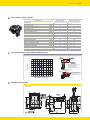
HOW TO READ THE SPECIFICATION
Part Number
Part Number
HG60-05-V-ST
Ezi-Servo 42XL Step Motor ⑩ Angular transmission error
Type of motor
① Type of output table supporting bearing
② Permissible Torque
③ Inertia moment
⑪ Permissible thrust load
(N)
4 (0.067°)
100
⑫ Permissible moment load
(N.m)
2
2330 x 10-7
⑬ Runout of output table surface
(mm)
0.01
(rpm)
300
(mm)
Gear ratio
1:5
⑭ Runout of output table inner/
outer diameter
⑮ Parallelism of output table
⑯ Degree of protection IP40
(mm)
0.005
IP40(IP20 for motor
Connector)
(Kg)
1.2
(N.m)
J : (Kg.m2)
④ Permissible speed
⑤ Gear ratio
Ball Bearing
HG60-05-V-ST
(min)
4.5
⑥ Maximum Holding Torque
N.m)
1.6
⑦ Resolution
(ppr)
10,000
⑧ Repetitive Positioning Accuracy
(sec)
±10 (0.0028°)
⑨ Lost Motion
(min)
2 (0.033°)
(IP20 for motor connector)
⑰ Mass
0.01
Show description of specification items
① Type of Output Table
Supporting Bearing
② Permissible torque
③ Inertia moment
④ Table Permissible Speed
⑤ Gear ratio
⑥ Maximum Holding Torque
⑦ Resolution
⑧ Repetitive Positioning Accuracy
⑨ Lost Motion
⑩ Angular transmission error
⑪ Permissible thrust load
⑫ Permissible moment load
⑬ Runout of output table surface
⑭ Runout of output table inner/
outer diameter
⑮ Parallelism of Output Torque
⑯ Degree of Protection IP40
(IP20 for motor connector)
⑰ Mass
The type of the bearing used for the output table.
The limit of mechanical strength of the reduction gear mechanism enables to make sure the applied
torque including acceleration torque and load fluctuation and it will not exceed the permissible torque.
Total sum of rotor inertia moment of the motor and the reduction gear of mechanism,
converted to a moment on the output table.
The output table speed can be tolerated by the mechanical strength of the reduction gear mechanism.
Deceleration mechanism to configure the number of teeth of two gears.
Hollow Rotary actuator can exert the maximum holding torque once the actuator is at standstill with
power supplied.
Needed number of pulse to rotate 1 revolution of output table.
A Value indicates the degree of error which is generated when positioning performs
repeatedly to the same position in the same direction.
The difference at the stopped angles achieved when the output table is positioned to the same position
during forward and reverse direction of motions. And difference is mainly caused by backlash of gear.
The difference between the theoretical rotation angle of the output table and the actual rotation angle.
And this value calculated from the input pulse number.
The permissible value of thrust load applied to the output table in the axial direction.
When a load is applied to a position away from the center of the output table, the output table receives a
tilting force and the permissible moment load refers to the permissible value of moment load
calculated by multiplying the offset distance from the center by the applied load.
The maximum value of runout of the mounted surface of the output table when the output table
rotates without load.
The maximum value of runout of the inner diameter or outer diameter of the table when the
output table rotates without load.
Actuator (plinth base) installed on the output side of the Table and value that indicates whether
the degree inclines.
IEC 60529, EN60034-5 (= IEC60034-5) classifies the dust resistance and waterproofing into grades.
A sum of Actuator configured as the output Table, deceleration mechanism, such as driving motor
plus the weight of all components.
Ezi-Actuator HG _ 6
/7
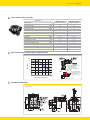
HG60 SERIES SPECIFICATIONS
Part Number
HG60-05-V-ST
HG60-05-V-ST-PR
Type of motor
Ezi-Servo 42XL Step Motor
Ezi-Servo 42XL Step Motor
Type of output table supporting bearing
Ball Bearing
Ball Bearing
Permissible Torque
(N.m)
4.5
4.5
Inertia moment
J : (Kg.m2)
2330 x 10-7
2330 x 10-7
Permissible speed
(rpm)
300
300
Gear ratio
1:5
1:5
Maximum Holding Torque
(N.m)
1.6
1.6
Resolution
(ppr)
10,000
10,000
Repetitive Positioning Accuracy
(sec)
±10 (0.0028°)
±10 (0.0028°)
Lost Motion
(min)
2 (0.033°)
2 (0.033°)
Angular transmission error
(min)
4 (0.067°)
4 (0.067°)
Permissible thrust load
(N)
100
100
Permissible moment load
(N.m)
2
2
Runout of output table surface
(mm)
0.015
0.015
Runout of output table inner/outer diameter
(mm)
0.015
0.015
Parallelism of output table
(mm)
0.03
0.03
Degree of protection IP40 (IP20 for motor connector)
IP40(IP20 for motor Connector) IP40(IP20 for motor Connector)
Mass
(Kg)
1.0
1.0
HG60 ROTATIONAL SPEED TORQUE CHARACTERISTIC
※2
※1
3.5
※3
3
Torque (N.m)
※3
2.5
※1 Runout pf output table surface
※2 Runout pf output table
Innerlouter Diameter.
※3 ParalIelism of output torque
2
1.5
Distance from Center
of Rotation L(mm)
1
Load(F(N)
0.5
0
0
50
100
150
200
250
Table Rotation Speed(rpm)
HG SERIES DIMENSIONS
(Unit : mm)
300
Max. Permissible moment
load with 2N m load, Table
displacement based on
60mm diameter δ≤ 10㎛
350
Moment Load(N.m)=0.001×F×L
Ezi-Actuator HG _ 8
/9
HG130 SERIES SPECIFICATIONS
Part Number
HG130-10-V-ST
HG130-10-V-ST-PR
Type of motor
Ezi-Servo 60L Step Motor
Ezi-Servo 60L Step Motor
Type of output table supporting bearing
Taper Roller Bearing + Ball Bearing Taper Roller Bearing + Ball Bearing
Permissible Torque
(N.m)
14
14
Inertia moment
J : (Kg.m2)
9216 x 10-6
9216 x 10-6
Permissible speed
(rpm)
200
200
Gear ratio
1:10
1:10
Maximum Holding Torque
(N.m)
12.5
12.5
Resolution
(ppr)
10,000
10,000
Repetitive Positioning Accuracy
(sec)
±10 (0.0028°)
±10 (0.0028°)
Lost Motion
(min)
2 (0.033°)
2 (0.033°)
Angular transmission error
(min)
3 (0.05°)
3 (0.05°)
Permissible thrust load
(N)
2000
2000
Permissible moment load
(N.m)
50
50
Runout of output table surface
(mm)
0.01
0.01
Runout of output table inner/outer diameter
(mm)
0.01
0.01
Parallelism of output table
(mm)
0.01
0.01
Degree of protection IP40 (IP20 for motor connector)
IP40(IP20 for motor Connector) IP40(IP20 for motor Connector)
Mass
(Kg)
6.1
6.1
HG130 ROTATIONAL SPEED TORQUE CHARACTERISTIC
※2
※1
16
14
※3
Torque (N.m)
12
※1 Runout pf output table surface
※2 Runout pf output table
Innerlouter Diameter.
※3 Parallelism of output torque
10
8
6
Distance from Center
of Rotation L(mm)
4
Load(F(N)
2
0
0
20 40
60 80 100 120 140 160 180 200
Table Rotation Speed(rpm)
HG SERIES DIMENSIONS
(Unit : mm)
Max. Permissible moment
load with 2N m load, Table
displacement based on
60mm diameter δ≤ 10㎛
Moment Load(N.m)=0.001×F×L
Specifications and Outline
HG200 SERIES SPECIFICATIONS
Part Number
HG200-10-V-ST
HG200-10-V-ST-PR
Type of motor
Ezi-Servo 86L Step Motor
Ezi-Servo 86L Step Motor
Type of output table supporting bearing
Taper Roller Bearing + Ball Bearing Taper Roller Bearing + Ball Bearing
Permissible Torque
(N.m)
50
50
Inertia moment
J : (Kg.m2)
85792 x 10-6
85792 x 10-6
Permissible speed
(rpm)
110
110
Gear ratio
1:10
1:10
Maximum Holding Torque
(N.m)
43
43
Resolution
(ppr)
10,000
10,000
Repetitive Positioning Accuracy
(sec)
±10 (0.0028°)
±10 (0.0028°
)
Lost Motion
(min)
2 (0.033°)
2 (0.033°
)
Angular transmission error
(min)
2 (0.033°)
2 (0.033°
)
Permissible thrust load
(N)
4000
4000
Permissible moment load
(N.m)
100
100
Runout of output table surface
(mm)
0.01
0.01
Runout of output table inner/outer diameter
(mm)
0.015
0.015
Parallelism of output table
(mm)
0.01
0.01
Degree of protection IP40 (IP20 for motor connector)
IP40(IP20 for motor Connector) IP40(IP20 for motor Connector)
Mass
(Kg)
15.5
15.5
HG200 ROTATIONAL SPEED TORQUE CHARACTERISTIC
※2
※1
60
50
Torque (N.m)
※3
40
※1 Runout pf output table surface
※2 Runout pf output table
Innerlouter Diameter.
※3 Parallelism of output torque
30
20
10
Load(F(N)
0
0
20
40
60
80
100
Table Rotation Speed(rpm)
HG SERIES DIMENSIONS
(Unit : mm)
Distance from Center
of Rotation L(mm)
Max. Permissible moment
load with 2N m load, Table
displacement based on
60mm diameter δ≤ 10㎛
120
Moment Load(N.m)=0.001×F×L
Ezi-Actuator HG _ 10
/ 11
HG275 SERIES SPECIFICATIONS
Part Number
HG275-10-V-ST
HG275-10-V-ST-PR
Type of motor
Ezi-Servo 86L Step Motor
Ezi-Servo 86L Step Motor
Type of output table supporting bearing
Taper Roller Bearing + Ball Bearing Taper Roller Bearing + Ball Bearing
Permissible Torque
(N.m)
55
55
Inertia moment
J : (Kg.m2)
111279 x 10-6
111279 x 10-6
Permissible speed
(rpm)
110
110
Gear ratio
1:10
1:10
Maximum Holding Torque
(N.m)
43
43
Resolution
(ppr)
10,000
10,000
Repetitive Positioning Accuracy
(sec)
±10 (0.0028°)
±10 (0.0028°)
Lost Motion
(min)
2 (0.033°)
2 (0.033°)
Angular transmission error
(min)
2 (0.033°)
2 (0.033°)
Permissible thrust load
(N)
4000
4000
Permissible moment load
(N.m)
100
100
Runout of output table surface
(mm)
0.01
0.01
Runout of output table inner/outer diameter
(mm)
0.015
0.015
Parallelism of output table
(mm)
0.01
0.01
Degree of protection IP40 (IP20 for motor connector)
IP40(IP20 for motor Connector) IP40(IP20 for motor Connector)
Mass
(Kg)
19.7
19.7
HG275 ROTATIONAL SPEED TORQUE CHARACTERISTIC
※2
※1
60
Torque (N.m)
50
※3
40
※1 Runout pf output table surface
※2 Runout pf output table
Innerlouter Diameter.
※3 Parallelism of output torque
30
20
Distance from Center
of Rotation L(mm)
10
Load(F(N)
0
0
20
40
60
80
100
120
Max. Permissible moment
load with 2N m load, Table
displacement based on
60mm diameter δ≤ 10㎛
Table Rotation Speed(rpm)
Moment Load(N.m)=0.001×F×L
HG SERIES DIMENSIONS
(Unit : mm)
ö4QFDJBM*OTUSVDUJDOTUPBTTFNCMFTFOTPS
1MFBTFVTFQSPVJEFECPMUBOEXBTIFS
%POPUVTFNPSFUIBO.YCPMU*UNBZDBVTFQSPEVDUEBNBHF
Ezi-Actuator HG _ 12
/ 13
DIMENSIONS OF HOME-SENSOR INSTALLATION.
HG60
(Unit : mm)
HG60/HG100 Common shielding plate
Dimension
HG100
(Unit : mm)
Mechanism Option
DIMENSIONS OF HOME-SENSOR INSTALLATION.
HG130
(Unit : mm)
HG130/HG200/HG275
Common shielding plate Dimension
HG200
(Unit : mm)
HG275
(Unit : mm)
Ezi-Actuator HG _ 14
DIMENSIONS OF HOME-SENSOR INSTALLATION.
NPN Type
Please use DC 5V, DC 24V power supply or less and consult the current value less than 100mA. If more than
100mA, please connect external register R. And sensor power supply and user controller power supply GND
should be a common.
•Pulse train input unit
---Pink lead wire N.C (Normally Closed) needs to be connected with brown lead wire
N.O (Normally Open) : Pink lead wire is not connected
•Controller integrated unit
---Pink lead wire N.C (Normally Closed) needs to be connected with brown lead wire
N.O (Normally Open) : Pink lead wire is not connected
PNP Type
Please use DC 5V, DC power supply or less and consult the current value less than 100mA. If more than
50mA, please connect external register R.
•Pulse train input unit
---Pink lead wire N.C (Normally Closed) needs to be connected with brown lead wire
N.O (Normally Open) : Pink lead wire is not connected
•Controller integrated unit
---Pink lead wire N.C (Normally Closed) needs to be connected with brown lead wire
N.O (Normally Open) : Pink lead wire is not connected
/ 15
Drive and Motor
Combination
PULSE INPUT DRIVE AND MOTOR COMBINATION
Unit Model Number
HG60-05-V-ST
Motor Model Number
EzM-42XL-A
Drive Model Number
EzS-PD-42XL-A
HG100-08-V-ST
EzM-60L-A
EzS-PD-60L-A
HG130-10-V-ST
EzM-60L-A
EzS-PD-60L-A
HG200-10-V-ST
EzM-86L-A
EzS-PD-86L-A
HG275-10-V-ST
EzM-86L-A
EzS-PD-86L-A
CONTROLLER EMBEDDED DRIVE AND MOTOR COMBINATION
Unit Model Number
Motor Model Number
Drive Model Number
HG60-05-V-ST-PR
EzM-42XL-A
EzS-NDR-42XL-A
HG100-08-V-ST-PR
EzM-60L-A
EzS-NDR-60L-A
HG130-10-V-ST-PR
EzM-60L-A
EzS-NDR-60L-A
HG200-10-V-ST-PR
EzM-86L-A
EzS-NDR-86L-A
HG275-10-V-ST-PR
EzM-86L-A
EzS-NDR-86L-A
Ezi-Actuator HG _ 16
/ 17
Pulse Input Drive
SPECIFICATIONS OF PULSE INPUT DRIVE
Motor Model
EzM-42 series
EzM-60 series
EzM-86 series
Driver Model
EzS-PD-42 series
EzS-PD-60 series
Input Voltage
24VDC ±10%
24VDC ±10%
EzS-PD-86 series
40~70VDC
Control Method
I/O
Signals
Function
Operating
Condition
Current Consumption
Closed loop control with 32bit DSP
Max 500mA (Except motor current)
Ambient
Temperature
In Use :0~55
In Storage :-20~70
Humidity
In Use :35~85%
In Storage :10~90%
Vib.Resist.
Rotation Speed
0.5G
Resolution(P/R)
Max.Input Pulse
Frequency
10000/Rev.Encoder model : 500, 1000, 1600, 2000, 3600, 5000, 6400, 7200, 10000
0~3000rpm
500KHz (Duty 50%)
Protection
Functions
Over current, Over speed, Step out, Over load, Over temperature, Over regenerated
voltage, Motor connect error, Encoder connect error, Low input voltage, Inposition
error, System error, ROM error, High input voltage
LED Display
Power status,Alarm status,In-Position status,Servo On status
In-Position Selection
Position Gain Selection
Pulse Input Method
Rotational Direction
Speed/Position \
Control Command
Input Signals
Output Signals
0~F(Selectable with rotary switch)
0~F(Selectable with rotary switch)
1-Pulse /2-Pulse (Selectable with DIP switch)
CW /CCW (Selectable with DIP switch)
Pulse train input
Position command pulse,Servo On/Off,Alarm reset (Photocoupler input)
In-Position,Alarm (Photocoupler output)
Encoder signal(A+,A-,B+,B-,Z+,Z-,26C31 of Equivalent),(Line Driver output)
DIMENSION OF PULSE INPUT DRIVE(mm)
(Unit : mm)
※Only for 86mm motor drive
(EzS-PD-886 eries)
Controller Embedded Drive
SPECIFICATIONS OF CONTROLLER EMBEDDED DRIVE
Motor Model
Driver Model
Input Voltage
EzM-60 series
EzM-86 series
EzS-NDR-60 series
24VDC ±10%
EzS-NDR-86 series
40~70VDC
Control Method
Closed loop control with 32bit DSP
Multi Axes Drive
Maximum 16 axes through Daisy-Chain
Position Table
Operating
Condition
Current Consumption
Function
EzM-42 series
EzS-NDR-42 series
24VDC ±10%
Ambient
Temperature
Humidity
256 motion command steps (Continuous,Wait,Loop,Jump and External start etc.)
Max 500mA (Except motor current)
In Use : 0~50℃
In Storage : -20~70℃
In Use : 35~85%(Non-condensing)
In Storage : 10~90%(Non-condensing)
Vib.Resist.
Rotation Speed
0.5G
Resolution(P/R)
10000/Rev.Encoder model : 500, 1000, 1600, 2000, 3600, 5000, 6400, 7200, 10000
Protection
Functions
LED Display
0~3000rpm
Over current, Over speed, Position tracking error, Over load, Over temperature, Over
regenerated voltage, Motor connect error, Encoder connect error, Motor voltage error,
In-Position error, System error, ROM error, Input voltage error, Position overflow error
Power status, Alarm status, In-Position status, Servo On status
I/O
Signals
In-Position Selection 0~15 (Selectable by parameter)
Position Gain Selection 0~15 (Selectable by parameter)
Rotational Direction CW / CCW (Selectable by parameter)
Input Signals
3 dedicated input (LIMIT+, LIMIT-, ORIGIN), 9 programmable input (Photocoupler)
Output Signal
1 dedicated output (Compare Out), 9 programmable output (Photocoupler),Brake signal
Communication Interface
Position Control
The RS-485 serial communication with PC Transmission speed :9,600~921,600bps
Incremental mode /Absolute mode
Data Range : -134,217,727 to +134,217,727pulse, Operating speed : Max. 500rpm
DIMENSION OF CONTROLLER EMBEDDED DRIVE(mm)
※Only for 86mm motor drive
(EzS-NDR-86 series)
Ezi-Actuator HG _ 18
/ 19
Motor Specifications and
Torque Characteristics
SPECIFICATIONS OF MOTOR (SAME FOR PULSE INPUT AND CONTROLLER EMBEDDED DRIVE)
Unit
EzM-42XL-A
EzM-60L-A
EzM-86L-A
Drive Method
-
Bi-Polar
Bi-Polar
Bi-Polar
Number of Phase
-
2
7.2
2
2
2.6
3.6
1.2
6
4
6.0
0.65
0.6
2.4
6.5
Model
Voltage
VDC
Current per Phase
A
Resistance per Phase
Ohm
Inductance per Phase
mH
Holding Torque
N.m
Weight
g
15.6
0.8
114
500
Length
mm
59
g.cm2
Rotor Inertia
2.4
8.5
800
2700
1600
3.9
117
Allowable Thrust Load
N
90
Lower than motor weight
Insulation Resistance
Mohm
100min (at 500VDC)
Insulation Class
-
Class B
Operating Temperature
°
C
0 to 55
MOTOR TORQUE CHARACTERISTICS (SAME FOR PULSE INPUT AND CONTROLLER EMBEDDED DRIVE)
EzM-60 series
400
300
200
20
10²
2.5
Torque (N m)
500
0
10¹
2
1.5
1
0.5
0
10¹
10³ 3x10³
Speed(RPM)
10²
10³ 3x10³
Speed(RPM)
※Measured Condition
Motor Voltage = 24VDC
Motor Current = Rated Current
(Refer to Motor Specification)
Drive = Ezi-SERVO-Plus R
※Measured Condition
Motor Voltage = 24VDC
Motor Current = Rated Current
(Refer to Motor Specification)
Drive = Ezi-SERVO-Plus R
EzM-42 series
EzM-60 series
700
600
3
Torque (N m)
Torque (mN m)
EzM-86 series
3
700
600
Torque (N m)
Torque (mN m)
EzM-42 series
500
400
300
200
20
0
10¹
10²
10³ 3x10³
Speed(RPM)
※Measured Condition
Motor Voltage = 40VDC
Motor Current = Rated Current
(Refer to Motor Specification)
Drive = Ezi-SERVO-Plus R
2.5
2
1.5
1
0.5
0
10¹
10²
10³ 3x10³
Speed(RPM)
※Measured Condition
Motor Voltage = 40VDC
Motor Current = Rated Current
(Refer to Motor Specification)
Drive = Ezi-SERVO-Plus R
9
8
7
6
15
4
3
2
1
0
10¹
10²
10³ 3x10³
Speed(RPM)
※Measured Condition
Motor Voltage = 70VDC
Motor Current = Rated Current
(Refer to Motor Specification)
Drive = Ezi-SERVO(EzR-PD-86Series)
Pulse Input Drive Setting
and Operating
PULSE INPUT DRIVE SETTING AND OPERATING
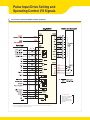
Pulse input and direction selection (SW1)
Position Controller Gain selection (SW2)
Resolution setting (SW3)
Status monitor LED
In-Position value setting (SW4)
Input/Output connection
(CN1)
Encoder connection (CN2)
Motor connection (CN3)
Power connection (CN4)
86mm motor drive only(EzS-PD-86 Series)
Pulse input and direction selection (SW1)
Position Controller Gain selection (SW2)
Resolution setting (SW3)
Status monitor LED
In-Position value setting (SW4)
Input/Output connection
(CN1)
Encoder connection (CN2)
Motor connection (CN3)
Power connection (CN4)
Ezi-Actuator HG _ 20
/ 21
SETTING AND OPERATING
Status Monitor LED
Function
Indication Color
PWR Green Power input indication
ON/OFF Condition
LED is turned ON when power is applied
Complete Positioning
Motion
INP
Yellow
SON
Orange Servo On/Off Indication
ALM
Red
Lights On when Positioning error reaches within
the preset pulse selected by rotary switch
Servo On : Lights On Servo Off : Lights Off
Flash when protection function is activated
(Identifiable which protection mode is activated
by counting the blinking times)
Alarm indication
•Protection functions and LED flash times
Protection
Over current
The current through power devices in inverter exceeds the limit value
2
Over speed
Motor speed exceed 3000rpm
3
Step out
Position value is higher than specified value in motor stop status
4
Over load
The motor is continously operated more than 5 second under
a load exceeding the max. torque
5
Over tempertature
Inside temperature of drive exceeds 55 °
C
6
Over regeneratived voltage
Back-EMF more high limit value※1
7
Motor Connect error
8
Encoder Connect error
The power is ON without connection of the motor cable to drive
Cable connection error with Encoder connector in drive
9
Low input voltage
Power source voltage is below limited value※2
10
Inposition error
After operation is finished,a position error occurs
11
System error
Error occurs in drive system
12
ROM error
14
Hight input voltage
Error occurs in parameter storage device(ROM)
Power source voltage is higher than limited value※3
Times
1
0.5s
2.0s
Alarm LED flash (ex :Step out)
Conditions
※1 Voltage limit of Back-EMF depends on motor model (Refer to the Manual)
※2 Low limit voltage value depends on motor model (Refer to the Manual)
※3 Limit value provided to drives depends on driver model (Refer to the Manual)
Pulse input and motor direction selection switch(SW1)
Indication
Switch Name
Functions
2P/1P
(pin #1)
Selecting pulse
input mode
Selectable 1-Pulse input mode or 2-Pulse input mode as
Pulse input signal.
ON : 1-Pulse mode / OFF :2-Pulse mode
※Default : 2-Pulse mode
DIR
(pin #2)
Switching Rotational
Direction
Based on CW(+Dir signal)input to driver.
ON : CCW(-Direction) / OFF : CW(+Direction)
※Default : CW mode
Direction Selection : ON
CCW Dir.
Direction Selection : OFF
CW Dir.
Pulse Input Drive Setting
and Operating
SETTING AND OPERATING
Position Controller Gain Selection switch(SW2)
The Position Controller Gain Switch allows for the correction of the motor position deviation after stopping caused
by load and friction. Depending on the motor load, the user may have to se-lect a different gain position to stabilize
and to correct positional error quickly.
To tune the controller
1. Set the switch to“0”Position.
2. Start to rotate the switch until system becomes stable.
3. Sotate the switch +/-1 ~ 2 position to reach better performance.
Proportional Gain※1
Position
Time Constant of the Integral part
0
1
1
1
1
2
2
1
3
3
1
4※2
4
1
5
5
1
6
6
2
1
7
2
2
8
2
3
9
2
4
A
2
5
B
3
1
C
3
2
D
3
3
E
3
4
F
3
5
※1 Value in the columns are in relative units. They only show the parameter changes depending on the switch’
s position.
※2 Default =4
Resolution selection switch (SW3)
The Number f pulse per revolution.
Position
Pulse/Rotation
Position
Pulse/Rotation
0
500※1
5
3600
1
500
6
5000
2
1000
7
6400
3
1600
8
7200
4
2000
9
10000※2
※1 Position‘0’Resolution Value Depends on Encodertype. when use 16000, 20000, 32000 Resolution Encoder, Resolution sets as 16000, 20000, 32000
※2 Default = 10,000
Position Value Setting switch(SW4)
To select the output condition of In-position signal. In-position output signal is generated when the pulse number
of positional error is lower than selected In-position value set by this switch after positioning command is executed.
Position
0
In-Position Value [Pulse ]Fast Response
0※1
1
1
2
2
3
3
4
4
5
5
6
6
7
7
※1 Default =0 ※ Please refer to User Manual for setup.
Position
8
9
A
B
C
D
E
F
In-Position Value [Pulse ]Accurate Response
0
1
2
3
4
5
6
7
Ezi-Actuator HG _ 22
Motor Connector(CN3)
NO.
Function
NO.
Function
1
A Phase
1
/B Phase
2
B Phase
2
B Phase
3
/A Phase
3
/A Phase
4
/B Phase
4
A Phase
Function
NO.
Function
GND
※ Only for 86mm motor drive.
Power Connector(CN4)
NO.
24VDC
1
2
GND
10%
1
2
40~70VDC
※ Only for 86mm motor drive.
Encoder connector(CN2)
NO.
1
Function
A+
Input
I/O
2
A-
Input
3
B+
Input
4
B-
Input
5
Z+
Input
6
Z-
7
5VDC
Output
8
5VDC GND
Output
9
Frame GND
-
10
Frame GND
-
Input
Input / Output signal(CN1)
NO.
1
Function
I/O
CW+(Pulse+)
Input
2
CW-(Pulse-)
Input
3
CCW+(Dir+)
Input
4
CCW-(Dir-)
5
A+
Output
6
A-
Output
7
B+
Output
8
B-
Output
9
Z+
Output
10
Output
11
ZAlarm
12
In-Position
Output
13
Servo On/Off
Input
14
Alarm Reset
Input
15
NC
16
BRAKE+
Output
17
BRAKE-
Output
18
S-GND
Output
19
24VDC GND
Input
20
24VDC
Input
※BRAKE function is optional
※There is no BRAKE function for 86mm motor drive.
Input
Output
-
/ 23
Pulse Input Drive Setting
and Operating
SYSTEM CONFIGURATION OF PULSE INPUT DRIVE
Motion Controller
Network
Motion Controller
PLC
① Signal Cable
② Encoder Extension Cable
③ Motor Extension Cable
④ Power Cable
Type
Power Cable
Motor Cable
Encoder Cable
Signal Cable
Standard Length
Max.Length
2m
30m
20m
30cm
20m
20m
Cable Option
1. Signal Cable
Available to connect between Control System and Ezi-SERVO.
Item
CSVO-S-
F
Length [m]
Remark
Normal Cable
CSVO-S-
M
Robot Cable
is for Cable Length.The unit is 1m and Max. 20m length.
2. Encoder Extension Cable
Available to extended connection between Encoder and Ezi-SERVO.
Item
CSVO-E-
F
Length [m]
Remark
Normal Cable
CSVO-E-
M
Robot Cable
is for Cable Length.The unit is 1m and Max. 20m length.
3. Motor Extension Cable
Available to extended connection between motor and Ezi-SERVO.
Item
CSVO-M-
F
Remark
Normal Cable
CSVO-M-
M
Robot Cable
Length [m]
is for Cable Length.The unit is 1m and Max. 20m length.
4. Power Cable
Available to connect between Power and Ezi-SERVO.
Item
CSVO-P-
F
Remark
Normal Cable
CSVO-P-
M
Robot Cable
Length [m]
is for Cable Length.The unit is 1m and Max. 20m length.
Ezi-Actuator HG _ 24
SYSTEM CONFIGURATION OF PULSE INPUT DRIVE (86mm MOTER)
Motion Controller
Network
Motion Controller
PLC
① Signal Cable
② Encoder Extension Cable
③ Motor Extension Cable
④ Power Cable
Type
Power Cable
Motor Cable
Encoder Cable
Signal Cable
Standard Length
Max.Length
2m
30m
20m
30cm
20m
20m
Cable Option
1. Signal Cable
Available to connect between Control System and Ezi-SERVO.
Item
CSVO-S-
F
Remark
Normal Cable
CSVO-S-
M
Robot Cable
Length [m]
is for Cable Length.The unit is 1m and Max. 20m length.
2. Encoder Extension Cable
Available to extended connection between Encoder and Ezi-SERVO.
Item
CSVO-E-
F
Length [m]
CSVO-E-
M
Remark
Normal Cable
Robot Cable
is for Cable Length.The unit is 1m and Max. 20m length.
3. Motor Extension Cable
Available to extended connection between motor and Ezi-SERVO.
Item
CSVO-M-
F
Remark
Normal Cable
CSVO-M-
M
Robot Cable
Length [m]
is for Cable Length.The unit is 1m and Max. 20m length.
4. Power Cable
Available to connect between Power and Ezi-SERVO.
Item
CSVO-P-
F
Remark
Normal Cable
CSVO-P-
M
Robot Cable
Length [m]
is for Cable Length.The unit is 1m and Max. 20m length.
/ 25
Pulse Input Drive Setting and
Operating Control I/O Signals
PULSE INPUT DRIVE EXTERNAL WIRING DIAGRAM
※ COUTION
Please refer to the Manual
when connects motor
extension cable.
Careful connection will
be required to protect any
damages.
※ Red Color is only 86mm motor drive. (EzS-PD-86 serise) Pay attention to re color that deseride the difference.
※ 1 There is no BRAKE function for 86mm motor drive.
Ezi-Actuator HG _ 26
/ 27
INPUT SIGNAL
Input signals of the drive are all hotocoupler protected. the signal shows the status of internal hotocouplers
[ON: onduction], OFF: on-cconduction ], ot isplaying the voltage levels f the signal.
Drive
CW(Pin:1,2),CCW(Pin:3,4)
Drive
Alarm Reset(Pin : 13) / Servo On/Off(Pin : 14)
CW, CCW Input
This signal can be used to receive a positioning pulse command from a user host motion controller.
The user can select 1-pulse input mode or 2-pulse input mode (refer to witch No.11, W1).The input schematic of
CW, CCW is designed for 5V TTL level. When using 5V level as an input signal, the resistor Rx is not used
and connect to he river directly. When the level of input signal is more than 5V, Rx resistor is re-quired. of the
resistor is absent, the drive will be amaged! If the input signal level is 12V, Rx value is 2.2kohm and 24V, Rx value
is .77kohm.
Alarm Reset
Servo On/Off Input
This input can be used only to djust the position by manually moving the motor shaft from the load-side.
By setting the signal [ON], the driver cuts off the power supply to the motor. Then, one can manually adjust
output position. When setting the signal back to [OFF ],the driver resumes the power to the motor and recovers
the holding torque. When driving a motor, one needs to set the signal [OFF].
※ By setting thea larm eset nput signal
[ON], ancel the Alarm output.
Before ancel the Alarm output, have to
remove the source of alarm.
Alarm Reset Input
When a protection mode has been activated, a signal to this alarm reset input cancels the Alarm output.
OUTPUT SIGNALS
Output signals from the driver are hotocoupler protected: alarm, in-Position and the line Driver utputs (encoder
signal). In the case of hotocoupler outputs, the signal indicates the status of internal hotocouplers ON: onduction],
OFF: non-conduction ], not isplaying the voltage levels of the signal..
Drive
Alarm(Pin : 11), In-Position(Rin : 12)
Drive
Encoder signal(Pin:5,6,7,8,9,10)
Alarm Output
The Alarm output indicates [ON] when the driver is in a normal operation. If a protection mode has been activated,
it goes [OFF ].A host controller needs to detect this signal and stop sending a motor driving command. When the
driver detects an abnormal operation such as overload or over current of the motor, it sets the Alarm
output to [OFF ], flashes the Alarm LED, disconnect the power to a motor and stops the motor simultaneously.
[Caution] Only at the Alarm output port, the photocoupler isolation is reverse. When the driver is in normal operation the Alarm output is [ON].
On the contrary when the driver is in abnormal operation that start protection mode, the alarm output is OFF].
Motor Speed
In-Position signal
In-Position Output
In-Position signal is [ON] when positioning is completed. This signal is [ON] when the motor position error
is within the value set by he witch SW4.
Encoder signal Output
The encoder signal is a line driver output. this can be used to confirm the stop position.
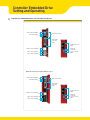
Controller Embedded Drive
Setting and Operating
CONTROLLER EMBEDDED DRIVE SETTING AND OPERATING
Network ID setting(SW1)
Network ID display
Status monitor LED
Input/Output
connection
(CN1)
RS-485 connection
(CN5)
Encoder connection(CN2)
Speed and
Terminator
resistor selection
(SW2)
Motor connection(CN3)
Power connection(CN4)
86mm motor drive only(EzS-NDR-86 Series)
Network ID setting(SW1)
Network ID display
Status monitor LED
Input/Output
connection
(CN1)
RS-485 connection
(CN5)
Encoder connection(CN2)
Motor connection(CN3)
Power connection(CN4)
Speed and
Terminator
resistor selection
(SW2)
Ezi-Actuator HG _ 28
/ 29
SETTING AND OPERATING
Status Monitor LED
Function
Indication Color
PWR Green Power input indication
ON/OFF Condition
LED is turned ON when power is applied
Complete Positioning
Motion
INP
Yellow
SON
Orange Servo On/Off Indication
ALM
Red
Lights On when Positioning error reaches within
the preset pulse selected by rotary switch
Servo On : Lights On, Servo Off : Lights Off
Flash when protection function is activated
(Identifiable which protection mode is activated
by counting the blinking times)
Alarm indication
•Protection functions and LED flash times
Protection
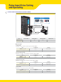
Over current
The current through power devices in inverter exceeds the limit value
2
Over speed
Motor speed exceed 3000rpm
3
Position tacking error
Position value is higher than specified value in motor stop status
4
Over load
The motor is continously operated more than 5 second under
a load exceeding the max.torque
5
Over tempertature
Inside temperature of drive exceeds 55 ℃
6
Over regeneratived voltage
Back-EMF more high limit value※1
7
Motor Connect error
8
Encoder Connect error
The power is ON without connection of the motor cable to drive
Cable connection error with Encoder connector in drive
9
Low input voltage
Power source voltage is below limited value※2
10
Inposition error
After operation is finished,a position error occurs
11
System error
Error occurs in drive system
12
ROM error
14
Input voltage error
Error occurs in parameter storage device(ROM)
Power source voltage is higher than limited value※3
Times
1
Alarm LED flash
(ex : Position tracking error)
Conditions
※1 Voltage limit of Back-EMF depends on motor model (Refer to the Manual)
※2 Low limit voltage value depends on motor model (Refer to the Manual)
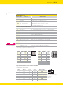
2.Network ID selection switch(SW1)
3.Encoder connector(CN2)
Position ID number Position ID number
0
0
1
1
2
2
3
3
NO.
Function
I/O
8
1
A+
Input
9
9
2
A-
Input
A
10
3
B+
Input
11
4
B-
Input
Input
8
B
4
4
C
12
5
Z+
5
5
D
13
6
Z-
Input
6
6
E
14
7
5VDC
Output
7
7
F
15
8
5VDC GND
Output
※Maximum 16 axis can be connected in one network.
9
Frame GND
----
10
Frame GND
----
4.Speed and Terminator resistor selection switch(SW2)
The purpose of this is to setting the communication speed andconnect a terminator resistor if drive
is installed at the end of network.
SW 2.1 used for connecting the terminator resistor. SW 2.2~SW 2.4 used for setting speed as follows.
SW 2.1
SW 2.2
SW 2.3
SW 2.4
–
OFF
OFF
OFF
9600
–
ON
OFF
OFF
19200
–
OFF
ON
OFF
38400
–
ON
ON
OFF
57600
–
OFF
OFF
ON
115200※1
–
ON
OFF
ON
230400
–
OFF
ON
ON
460800
–
ON
ON
ON
921600
※ 고속 통신을 위해 상용의 PCI Bus type RS-485 통신용 보드를 사용 가능합니다. (대리점에 문의 요망)
Baud rate[bps]
※1
: Default setting value
If SW2.1 is OFF,terminator resistor
is disconnected.
If SW2.2 is ON,terminator resistor
is connected.
Controller Embedded Drive
Setting and Operating
SETTING AND OPERATING
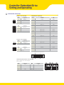
5.Motor connector(CN3)
8.Input/Output signal(CN1)
NO.
Function
NO.
1
A Phase
1
Function
LIMIT+
I/O
Input
2
B Phase
3
/A Phase
2
LIMIT-
Input
3
ORIGIN
4
/B Phase
Input
4
Digital In1
Input
5
Digital In6
Input
6
Digital In7
Input
NO.
Function
7
Compare Out1
Output
1
/B Phase
8
Digital Out1
Output
2
B Phase
9
Digital Out2
Output
3
/A Phase
10
Digital Out3
Output
A Phase
11
Digital Out4
Output
12
Digital Out5
Output
13
Digital Out6
Output
14
Digital In2
Input
15
Digital In3
Input
16
Digital In4
Input
17
Digital In5
Input
18
Digital In8
Input
19
Digital In9
Input
20
Digital Out7
Output
21
Digital Out8
Output
22
Digital Out9
Output
4
※Only for 86mm motor drive.
6.Power connector(CN4)
NO.
Function
1
24VDC ±10%
2
GND
23
BRAKE+
Output
NO.
Function
24
BRAKE-
Output
1
GND
40~70VDC
25
24VDC GND
Output
26
24VDC
24VDC
2
※Only for 86mm motor drive.
※BRAKE function is optional.
※There is no BRAKE function for 86mm motor drive.
7.RS-485 Communication connector(CN5)
There is converter for connecting PC.
1)RS-232 to RS-485
NO.
1
Function
Function
GND
NO.
6
2
GND
7
GND
3
Data+
8
Data+
4
GND
LED 1,3
Drive status
5
GND
LED 2,4
Communication status
GND
Ezi-Actuator HG _ 30
/ 31
Controller Embedded Drive
System Configurations
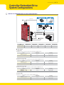
CONTROLLER EMBEDDED DRIVE SYSTEM CONFIGURATIONS
✽Option
⑤ RS-485 Cable
⑥
RS-232 input
• 3 dedicated and 9 programmable Inputs
• 1 dedicated and 9 programmable outputs
① Signal Cable
② Encoder Extension Cable
③ Motor Extension Cable
④ Power Cable
Type
Standard Length
Signal Cable
–
Encoder Cable
30cm
Motor Cable
30cm
Power Cable
–
RS-485 Cable
–
Max.Length
20m
20m
20m
2m
30m
Cable Option
1. Signal Cable
Available to connect between Control System and Ezi-SERVO Plus-R.
Item
CSVR-SCSVR-S-
Length [m]
F
M
Remark
Normal Cable
Robot Cable
is for Cable Length.The unit is 1m and Max.20m length.
2. Encoder Extension Cable
Available to extended connection between Encoder and Ezi-SERVO Plus-R.
Item
CSVO-E-
F
Remark
Normal Cable
CSVO-E-
M
Robot Cable
Length [m]
is for Cable Length.The unit is 1m and Max.20m length.
3. Motor Extension Cable
Available to extended connection between motor and Ezi-SERVO Plus-R.
Length [m]
Remark
Item
CSVO-M-
F
Normal Cable
CSVO-M-
M
Robot Cable
is for Cable Length.The unit is 1m and Max.20m length.
4. Power Cable
Available to connect between Power and Ezi-SERVO Plus-R.
Item
CSVO-PCSVO-P-
Length [m]
F
M
is for Cable Length.The unit is 1m and Max.20m length.
Remark
Normal Cable
Robot Cable
Controller Embedded Drive
System Configurations
CONTROLLER EMBEDDED DRIVE SYSTEM CONFIGURATIONS
RS-485 Cable
Item
CGNR-R-0R6F
Length [m]
0.6
CGNR-R-001F
1
CGNR-R-1R5F
1.5
CGNR-R-002F
2
CGNR-R-003F
3
CGNR-R-005F
5
Remark
Normal Cable
Option
6. FAS-RCR(RS-232C to RS-485 Converter)
Item
Specification
Comm.Speed
Max.115.2Kbps
Comm.Distance
RS-232C :Max.15m RS-485 :Max.1.2km
Connector Type
RS-232C : DB9 Female, RS-485 : RJ-45
Operating System
Windows 98/2000/XP/Vista
Dimension
50X75X23mm
Weight
38g
Power
Powered from PC (Usable for external DC5~24V)
RS-232C Cable
Item
CGNR-C-002F
Length [m]
2
Remark
CGNR-C-003F
3
Normal Cable
CGNR-C-005F
5
7. TB-Plus(Interface Board)
Available to connect more conveniently between Input/Output signal and Ezi-SERVO Plus-R.
Interface Cable
Available to Connect between TB-Plus Interface Board and Ezi-SERVO Plus-R.
Item
CIFD-SCIFD-S-
Length [m]
F
M
□is for Cable Length.The unit is 1m and Max.20m length.
Remark
Normal Cable
Robot Cable
Ezi-Actuator HG _ 32
CONTROLLER EMBEDDED DRIVE SYSTEM CONFIGURATIONS (86mm MOTOR)
✽Option ⑥
⑤ RS-485 Cable
RS-232 input
• 3 dedicated and 9 programmable Inputs
• 1 dedicated and 9 programmable outputs
① Signal Cable
② Encoder Extension Cable
③ Motor Extension Cable
④ Power Cable
Cable Option
1. Signal Cable
Available to connect between Control System and Ezi-SERVO Plus-R.
Item
CSVO-S-
F
Length [m]
CSVO-S-
M
Remark
Normal Cable
Robot Cable
is for Cable Length.The unit is 1m and Max.20m length.
2. Encoder Extension Cable
Available to extended connection between Encoder and Ezi-SERVO Plus-R.
Item
CSVO-E-
F
Remark
Normal Cable
CSVO-E-
M
Robot Cable
Length [m]
is for Cable Length.The unit is 1m and Max.20m length.
3. Motor Extension Cable
Available to extended connection between motor and Ezi-SERVO Plus-R.
Item
CSVO-M-
F
Remark
Normal Cable
CSVO-M-
M
Robot Cable
Length [m]
is for Cable Length.The unit is 1m and Max.20m length.
4. Power Cable
Available to connect between Power and Ezi-SERVO Plus-R.
Item
CSVO-P-
F
Remark
Normal Cable
CSVO-P-
M
Robot Cable
Length [m]
is for Cable Length.The unit is 1m and Max.20m length.
/ 33
Controller Embedded Drive
System Configurations
CONTROLLER EMBEDDED DRIVE SYSTEM CONFIGURATIONS (86mm MOTOR)
5. RS-485 Cable
Item
Length [m]
0.5
CGNR-R-0R6F
CGNR-R-001F
1
CGNR-R-1R5F
1.5
CGNR-R-002F
2
CGNR-R-003F
3
CGNR-R-005F
5
Remark
Normal Cable
Option
6. FAS-RCR(RS-232C to RS-485 Converter)
Item
Specification
Comm.Speed
Max.115.2Kbps
Comm.Distance
RS-232C : Max.15m, RS-485 :Max.1.2km
Connector Type
RS-232C : DB9 Female, RS-485 : RJ-45
Operating System
Windows 98/2000/XP/Vista
Dimension
50X75X23mm
Weight
38g
Power
Powered from PC (Usable for external DC5~24V)
RS-232C Cable
Item
CGNR-C-002F
Length [m]
2
Remark
CGNR-C-003F
3
Normal Cable
CGNR-C-005F
5
7. TB-Plus(Interface Board)
Available to connect more conveniently between Input/Output signal and Ezi-SERVO Plus-R.
Interface Cable
Available to Connect between TB-Plus Interface Board and Ezi-SERVO Plus-R.
Item
Length [m]
CSVO-S-
F
CSVO-S-
M
□is for Cable Length.The unit is 1m and Max.20m length.
Remark
Normal Cable
Robot Cable
Ezi-Actuator HG _ 34
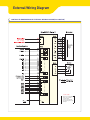
External Wiring Diagram
CONTROLLER EMBEDDED DRIVE EXTERNAL WIRING DIAGRAM
※ COUTION
Please refer to the Manual
when connects motor
extension cable.
Careful connection will
be required to protect any
damages.
/ 35
External Wiring Diagram
CONTROLLER EMBEDDED DRIVE EXTERNAL WIRING DIAGRAM(86mm MOTOR)
※ COUTION
Please refer to the Manual
when connects motor
extension cable.
Careful connection will
be required to protect any
damages.
Ezi-Actuator HG _ 36
/ 37
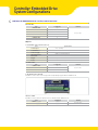
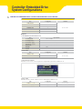
GUI (Graphic User Interface)
Screen shot
CONTROLLER EMBEDDED DRIVE USER GUI
Controller Lists and Motion Test
This screen display the controller list that connected to system.
You can make a single move,jog and origin command and also the
motor status is displayed.
Parameter List
All of the parameters are displayed and modified
on this screen.
Axis Parameter Setup
You can select various parameters that frequently used.
(ex :sensor input logic)
Motion Repeat and Monitor Status
Target position, speed, delay time and repeat count are selected for
repeat motion test.Motion library(DLL)is also displayed on screen.
I/O Monitoring and Setting
You can select various digital input and output signals of
controller.
Position Table
You can edit the position table and execute it.The position table
data can be saved and loaded from Flash ROM and Windows file.
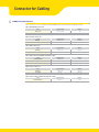
Connector for Cabling
CONNECTOR FOR CABLING
These connectors are serviced together with Ezi-SERVO Plus-R except when purchasing option cables.
CN1 : Input/Output Connector
Item
Specification
Maker
Connector
10126-3000PE
3M
10326-52FO-008
3M
Shell
CN2 : Encoder Connector
Item
Housing
Terminal
Specification
Maker
51353-1000
MOLEX
56134-9000
MOLEX
CN3 : Motor Connector
Item
Specification
Maker
Housing
Terminal
5557-04R
MOLEX
5556T
MOLEX
Item
Specification
Maker
Terminal Block
Housing
Terminal
AK950-4
PTR
3191-4RI
MOLEX
138IT
MOLEX
CN3 : Motor Connector(86mm motor drive only)
CN4 : Power Connector
Item
Specification
Maker
Housing
Terminal
5557-02R
MOLEX
5556T
MOLEX
Item
Specification
Maker
Terminal Block
AK950-2
PTR
CN4 : Power Connector(86mm motor drive only)
Ezi-Actuator HG _ 38
MEMO
/ 39
ཱྀ j GYWXWGmhz{ljoGjUSGsUGG
hGyGyUG
YWXYUGWYVGWY
Rm #1202, Bucheon Technopark 401 Dong, Yakdae-dong, Wonmi-gu, Bucheon-si Gyeonggi-do, Rep. Of Korea ( Zip : 420-734 )
Tel : 82-32-234-6300~1, 6303~10 / Fax : 82-32-234-6302 / Email:[email protected] / website : www.fastech.co.kr
811 E Plano Parkway, Suite 110A, Plano, TX 75074 USA
Toll Free: 877-905-4428 972-218-0210
Email: [email protected] / website: www.fastechamerica.com