1
United States Patent [191
[11]
Yamada
[45]
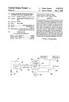
[54] TEMPERATURE DETECTION METHOD
4,959,651
Patent Number:
Date of Patent:
Sep. 25, 1990
OTHER PUBLICATIONS
AND APPARATUS
User's Manual of TLCS.—42,47,470, published by To
[75] Inventor: Tetsuro Yamada, Ibaraki, Japan
[73] Assignee: Kabushiki Kaisha Toshiba, Kawasaki,
Japan
[21] Appl. No.: 200,893
Primary Examiner-William M. Shoop, Jr.
Assistant Examiner-Brian K. Young
Attorney, Agent, or Firm—-Cushman, Darby & Cushman
[22] Filed:
[57]
[30]
Jun. 1, 1988
Japan .............................. .. 62-195899
[51]
Int. 01.5 ............................................ .. H03M 1/20
[52]
US. Cl. .................................. .. 341/131; 341/118;
[58]
Field of Search ............. .. 341/118, 119, 131, 132,
341/155
341/139, 148, 153, 154, 156, 158, 159, 160;
364/557, 571.01; 340/501; 324/105, 65 R, 115;
374/172
[56]
U.S. PATENT DOCUMENTS
8/1980
4,575,806
3/1986 Aldrich et a1, ,.
perature detected thereby. The temperature detector is
provided with an A/D conversion device to generate
digital temperature data corresponding to the analog
voltage input thereto, a reference voltage range setting
device to set the reference voltage range to the A/D
conversion device, and a reference voltage range
changing device. The A/D conversion device com»
pares the analog voltage with the reference voltage
which varies within the set reference voltage range.
The reference voltage range is automatically changed
References Cited
4,216,675
ABSTRACT
A temperature detector including a temperature sensor
to generate an analog voltage corresponding to a tem
Foreign Application Priority Data
Aug. 5, 1987 [JP]
shiba Corp., publication date: Apr., 1986.
Nagata et a1. ..... ..
______ ,_ 340/501
FOREIGN PATENT DOCUMENTS
by the reference voltage range changing device not
only to obtain a desired resolution of temperature in a
normal operating mode, but also to detect a malfunction
of the temperature sensor in a malfunction detection
mode‘
1451545 10/1976 United Kingdom .
9 Claims, 2 Drawing Sheets
35
‘f’
Vc
37
'1
VAREF I,“
H
UUT255
H
OUTZSI.
1 “A!”
T. [WAR
II:m
[JEEDUER
@1111
1117
UUTU
s
2
01117
TART
n
H
m‘o \ j OUTH EUUNTER
21
STUP CLOCK
{I
|:
l
'1
~
\
/<7
II
I]
23 17 zinc
39
:,I:
l——l—-4|:RANGE
1
4,959,651
2
terminal EDC of A/D converter 3. The eight-bit count
TEMPERATURE DETECTION METHOD AND
signal 21 from counter 15 is applied to input terminals
APPARATUS
1N7 to INO of decoder 13, and is also output, as parallel
data, from output terminals DATA 7 to DATA 0 of
BACKGROUND OF THE INVENTION
5 A/D converter 3. Resistors 25, 27 and 29 are externally
connected to integrated circuit 5 of A/D converter 3.
1. Field of the Invention
Resistor 25 is connected between the two reference
The present invention relates, in general, to tempera
voltage input terminals VA R E1: and VASS. The reference
ture detectors. More particularly, the invention relates
voltage input terminal VAREF is connected to a DC
to temperature detectors including A/D converters.
IO power supply Vc through resistor 27. The reference
2. Description of the Prior Art
A temperature detector is known which outputs a
voltage input terminal VASS is connected to ground
digital signal to a control device, such as a microcom
puter, in accordance with a temperature detected by a
temperature sensor. The temperature detector includes
through resistor 29.
an A/D converter to convert an analog signal corre
starts to count in synchronism with clock signal 17, and
sponding to the temperature into the digital signal. An
eight-bit count signal 21 is successively incremented.
Decoder 13 makes respective output terminal voltages
thereof successively high in accordance with count
signal 21. For example, when count signal 21 is zero,
only output terminal OUTO is made high, and when
count signal 21 is one, only output terminal OUTl is
made high. Consequently, the analog switches of switch
When start signal 19 applies a rising edge to counter
15, the count of counter 15 is reset, and then counter 15
example of such an A/D converter is disclosed in the
user’s manual of TLCS-42,47,470 published by T0
SHIBA CORP. in Man, 1986. In this user’s manual, an
A/D converter has input terminals VAREF and V455
across which the reference analog voltage is applied,
and an analog input terminal AIN to which the analog
voltage to be converted is applied. The A/D converter
20
group 11 are successively closed, one at a time, causing
also includes resistors connected in a ladder arrange
the voltage which is input to the non-inverting input
25
ment and a comparator. The reference analog voltage is
terminal (+) of comparator 7 to be progressively in
divided into a voltage value corresponding to one bit by
creased in a stepwise manner from a value which is
the ladder resistors. A/D conversion is performed with
practically equal to the voltage applied to the reference
the comparator comparing the input analog voltage
with the divided voltage value sequentially.
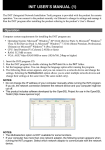
A conventional temperature detector including the
A/D converter will be explained referring to FIG. 2.
The A/D converter 3 includes circuit 5 fabricated as
an IC. The voltage applied to an analog voltage input
terminal AIN is input to an inverting input terminal (—)
of comparator 7. A voltage dividing circuit 9 includes
two hundred and ?fty-seven resistors connected in se
voltage input terminal VASS towards a value which is
30
practically equal to the voltage applied at the reference
voltage input terminal VAREF. When the stepwise volt
age input to the non-inverting input terminal (+) of
comparator 7 becomes larger than the voltage which is
applied to the analog voltage input terminal (—) of
comparator 7, the output of comparator 7 is inverted
from a low level to a high level. When the output of
comparator 7, i.e., stop signal 23 becomes a high level,
counter 15 ceases counting and count signal 21 at this
connected to reference voltage input terminals VAREF
time is latched. Since the output of comparator 7 is also
and VASS, respectively. The voltage at each voltage
division point of voltage dividing circuit 9 is input into 40 given to the end-conversion terminal EOC, the voltage
ries. The two ends of voltage dividing circuit 9 are
the analog input terminal of one of two hundred and
of ECG also becomes a high level, and the termination
?fty-six analog switches, respectively, together forming
of A/D conversion is thereby detected. Count signal 21
a switch group 11. The analog output terminals of these
analog switches are mutually connected and further
latched at this time is output from the data output termi
nals DATA 7 to DATA 0 as an eight-bit digital signal,
connected to a non-inverting input terminal (+) of 45 whose value corresponds to the analog voltage which is
applied to the input terminal AIN.
comparator 7. A decoder 13 produces a high level out
put on one of its two hundred and ?fty-six output termi
nals (labeled OUT255 to OUTO) in accordance with an
When A/D converter 3 is used in the temperature
detector of, for example, a refrigerator, the analog volt
age input terminal AIN is connected to a connection
1N7 to 1N0. The output from each of terminals OUT255 50 point of a temperature sensor 31 and a resistor 33. Tem
perature sensor 31 is provided in a freezer compartment
to OUTO of decoder 13 is applied to the digital input
of the refrigerator and may consist of a thermistor hav
terminal of one of the analog switches, respectively. An
ing a negative temperature characteristic. The other
eight-bit binary counter 15 starts to count in synchro
ends of temperature sensor 31 and resistor 33 are con
nism with a clock signal 17 which is input to a clock
input terminal CLOCK thereof from a clock terminal 55 nected to the DC power supply Vc and ground, respec
tively. As the temperature detector of a refrigerator, the
CLK of A/D converter 3. Counter 15 is reset by a
circuit must respond to temperatures around —20° C. in
leading edge of a start signal 19 which is input to a
the freezer compartment. The temperature resolution of
start-counting terminal START thereof from a start
about 0.1° C. is also required in the A/D conversion.
conversion terminal STC of A/D converter 3. An
eight-bit count signal 21, which is output from output
Therefore, conventionally, a temperature in a range
having a width of twenty degrees from —-30° C. to
terminals OUT7 to OUTO, is incremented in synchro
nism with clock signal 17.
.
— 10° C. is converted to eight-bit digital data so that the
When a stop signal 23 input into a stop-count terminal
temperature resolution of about 0.08° C. can be realized.
eight-bit digital signal that is applied to input terminals
STOP becomes high, counter 15 stops counting, and
The temperature in the freezer compartment, which is
count signal 21 at this time is latched. The stop signal 23 65 detected by temperature sensor 31, is converted to the
is provided by the output of comparator 7 and is input
voltage Vth at the connection point of temperature
to the stop-count terminal STOP of counter 15. The
sensor 31 and resistor 33, and the converted voltage Vth
stop signal 23 is also output from an end-conversion
is input to the terminal AIN. Therefore, for example,
3
4,959,651
when the DC power supply Vc is 5.0 volts, the temper
ature in the range having a width of twenty degrees
from —30° C. to —ylO' C. is converted to the voltage
4
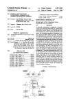
The reference voltage input terminal VAREF of inte
grated circuit 35 is connected to the DC power supply
Vc. An externally connected resistor 41 is connected
between the two reference voltage input terminals
VA RE1: and VASS. The reference voltage input terminal
VASS is connected to ground through a resistor 43. An
N PN transistor 45 is connected parallel with resistor 43
with the collector thereof being connected to the termi
nal VASS, while the emitter thereof is connected to
Vth which can range from 1.5 volts to 4.0 volts. The
resistance of resistors 25, 27 and 29 are, therefore, deter
mined so as to provide respective voltages of 4.0 volts
and 1.5 volts to be applied to the two reference voltage
input terminals VAREFand VASS. Since the voltage Vth
is then converted to the eight-bit digital data in the
range from 1.5 volts to 4.0 volts, the resolution for this
ground. The base of transistor 45 is connected to con
trol terminal CT of integrated circuit 35 and is also
pulled up to DC power supply Vc through a pullup
resistor 47.
When this A/D converter 37 is used for the tempera
voltage Vth is about 10 millivolts corresponding to
0.08" C.
In the conventional temperature detector mentioned
above, since the voltage applied to the two reference
ture detector of a refrigerator, a temperature sensor 49
voltage input terminals VAREFand VASS is simply deter
mined by the voltage dividing circuit consisting of resis
tors 25, 27 and 29, the input voltage range for which
A/D conversion is possible is ?xed. Consequently, in
is connected thereto. In other words, temperature sen~
sor 49 is connected between the DC power supply V0
and ground through a resistor 51, and the junction be
order to achieve the required resolution with a small bit
tween temperature sensor 49 and resistor 51 is con
nected to the analog voltage input terminal AIN of
integrated circuit 35. Temperature sensor 49 consists of
number, the voltages applied to the two reference volt
age input terminals have to be restricted. So, it is not
possible to detect malfunctions of temperature sensor
31, such as short circuiting or open circuiting, which
a well-known thermistor which has a negative tempera
ture characteristic and detects the temperature in a
freezer compartment of a refrigerator (not shown). As a
causes the voltage of the terminal AIN to be DC power
25 result of the temperature characteristic of temperature
supply voltage or zero.
sensor 49, the voltage Vth of the junction changes in
accordance with the temperature in the freezer com
partment, which is detected by temperature sensor 49.
The resistance of resistor 51 is determined such that the
voltage Vth changes within an appropriate range in
accordance with the temperature to be set for the
freezer compartment. In this embodiment, when a DC
power supply Vc is 5.0 volts, the resistance of resistor
51 is determined such that the voltage Vth is 1.5 volts
SUMMARY OF THE INVENTION
It is an object of the present invention to select the
range over which a temperature detector may operate
to achieve a desired resolution of temperature.
To accomplish the object described above, the pres
ent invention provides a temperature detection method
and apparatus. An A/D conversion device generates a
digital temperature data. A reference voltage range
setting device sets the reference voltage range for the
35
A/D conversion device. A reference voltage range
C., and the voltage Vth is 2.0 volts when the freezer
temperature is —26° C. In other words, the resistance of
resistor 51 is determined such that the voltage Vth rises
one volt higher as the temperature rises eight degrees
changing device is also provided. An analog voltage
corresponding to a temperature detected by a tempera
ture sensor is applied to the A/D conversion device.
The A/D conversion device compares the analog volt
age, which varies within the set reference voltage
range, with the reference voltage range. The reference
higher.
The resistances of resistors 41 and 43 are determined
voltage range changing device shifts the set reference
voltage range to another reference voltage range.
45
BRIEF DESCRIPTION OF THE DRAWINGS
The present invention is best understood with refer
ence to accompanying drawings in which:
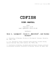
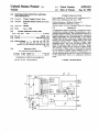
FIG. 1 is a schematic circuit diagram illustrating one
embodiment of the present invention; and
FIG. 2 is a schematic circuit diagram illustrating a
prior art temperature detector.
DETAILED DESCRIPTION OF THE
PREFERRED EMBODIMENT
when the freezer temperature is —30" C., the voltage
Vth is 4.0 volts when the freezer temperature is — 10°
such that when transistor 45 turns OFF, the voltage
applied to the reference voltage input terminal VASS is
2.0 volts. Consequently, when a low-level changeover
signal 39 is applied to the base of transistor 45 to turn
transistor 45 OFF, the analog input voltage range for
which A/D conversion is possible becomes from 2.0
volts to 5.0 volts, i.e., a width of 3.0 volts. Therefore,
the resolution of the eight-bit A/D conversion for the
voltage Vth applied to the terminal AIN is about 12.0
millivolts, corresponding to 0.096‘ C. So, the tempera
ture resolution of about 01° C., which is required in the
temperature detector of the refrigerator, can be
55 achieved. Furthermore, a temperature in a range includ
ing —20“ C., which is a typical desired temperature for
Referring to the accompanying drawings, an embodi
a freezer compartment, can be converted into a digital
ment of the present invention will be described.
value.
Circuit 35 of an A/D converter 37 includes the same
If a continuity failure of temperature sensor 49 oc
construction as integrated circuit 5 of A/D converter 3 60 curs, the voltage Vth of the junction point becomes the
shown in FIG. 2, with the exception that integrated
circuit 35 has an input voltage range changeover termi
volts. If a disconnection failure of temperature sensor 49
nal RANGE and a control terminal CT in addition. A
occurs, the voltage Vth becomes 0 volts. However, if
changeover signal 39 from a microcomputer (not
shown) is input to the terminal RANGE and is output
from the terminal CT. A more detailed description of
integrated circuit 35 and the action thereof will there
fore be omitted as redundant.
same high voltage as the DC power supply, i.e., 5.0
transistor 45 is turned ON in response to a high level
65
changeover signal 39, the analog input voltage range for
which A/D conversion is possible becomes from 0 volts
to 5.0 volts, i.e., a width of 5.0 volts. Consequently,
continuity failures and disconnection failures of temper
5
4,959,651
6
ature sensor 49 can be detected. The voltage of change
over signal 39 can be made to change between a low
3. A temperature detector according to claim 2,
wherein the selecting means includes a plurality of resis=
level and a high level periodically by the output of the
microcomputer. When changeover signal 39 is at a low
level, the temperature in the freezer compartment is
tors connected between a DC power supply and
detected with high resolution. When changeover signal
A/D conversion means being connected to different
locations along the resistors, at least one of the resistors
ground, the upper limit input terminal of the A/D con
version means and the lower limit input terminal of the
39 is at a high level, a continuity or disconnection fail
being short-circuited by the switching means.
ure of temperature sensor 49 can be detected.
4. A temperature detector according to claim 3,
As is well known from the above description, in this
wherein the switching means includes a transistor
turned ON and OFF sequentially with a period of pre
embodiment, since the reference voltage input terminal
VAREF is directly connected to DC power supply V0
determined time by a control signal input thereto.
and the reference voltage input terminal V455 is con
5. A temperature detector according to claim 2,
nected to the ground line through a parallel circuit
wherein the selecting means includes a plurality of resis
employing resistor 43 and transistor 45, the range of 15
tors connected between a DC power supply and
analog input voltages for which A/D conversion is
ground, the upper limit input terminal of the A/D con
carried out can be changed by turning ON or turning
version means being connected to the DC power supply
OFF transistor 45. Therefore, the desired high resolu
and the lower limit input terminal of the A/D conver
tion of temperature can be obtained even with an inex
sion means being connected to ground through at least
pensive A/D converter using a small bit number when 20 one of the resistors, at least one of the resistors being
transistor 45 is turned OFF. Furthermore, the failure of
short-circuited by the switching means.
temperature sensor 49, such as a continuity failure or a
6. A temperature detector according to claim 5,
disconnection failure, can be detected when transistor
wherein the switching means includes a transistor
45 is turned ON.
turned ON and OFF sequentially with a period of pre
The present invention has been described with re 25 determined time by a control signal input thereto.
spect to a speci?c embodiment. However, other em
7. A temperature detector according to claim 2,
bodiments based on the principles of the present inven
wherein the A/D conversion means includes:
tion should be obvious to those of ordinary skill in the
counter means for outputting a digital signal in accor
art. For example, in place of transistor 45, a mechanical
dance with a clock signal input thereto;
decoder means for outputting a series of selection
switching element such as a relay contact may be used.
signals in accordance with the digital signal;
Moreover, it is also possible for reference voltage input
means for generating a reference voltage within a
terminal VAREF to be connected to the DC power sup
ply Vc through a parallel circuit of a resistor and a
switching element such as a transistor, while the other
reference voltage input terminal VASS may be directly
connected to ground. Furthermore, the parallel circuit
reference voltage range selected by the selecting
means in accordance with each of the selection
35
each of the generated reference voltages, the
counter means being stopped and the digital signal
being output as the digital data in response to the
of a resistor and a switching element such as a transistor
may be connected between the reference voltage input
terminal VAREF and VASS. The function of counter 15
could be realized by the microcomputer. Such embodi
ments are intended to be covered by the claims.
What is claimed is:
1. A temperature detector comprising:
temperature sensing means for generating an analog
voltage corresponding to a detected temperature;
45
means for selecting one of a plurality of reference
voltage ranges, the selecting means including
switching means for selecting a reference voltage
range which includes an analog voltage generated
comparing means.
8. A temperature detector according to claim 7,
wherein the reference voltage generating means in
cludes a voltage dividing circuit employing resistors
connected in series between the two input terminals and
switches to make the reference voltage vary stepwise in
accordance with the selection signal, the switches being
connected to the connection points of the resistors,
respectively.
9. A method for changing a resolution of a tempera
ture detector comprising the steps of:
setting a voltage range within which a reference volt‘
by the temperature sensing means when a failure
has occurred in the temperature sensing means; and
A/D conversion means for outputting digital data
age varies;
comparing an input analog voltage corresponding to
corresponding to the analog voltage from the tem
a detected temperature with the reference voltage
perature sensing means by comparing the analog
voltage with the reference voltage range selected
by the selecting means.
signals; and
means for comparing the input analog voltage with
as it varies within the set range and generating a
digital data corresponding to the analog voltage
.
with an A/D converter; and
2. A temperature detector according to claim 1,
wherein the A/D conversion means includes two input
periodically shifting the set voltage range to another
voltage range in order to detect a failure in the
temperature detector.
terminals to which an upper limit and a lower limit of a
reference voltage range is input, respectively.
#
65
i
it
1|!
It