1
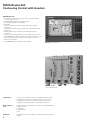
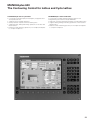
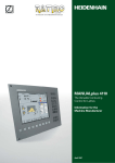
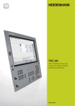
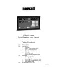
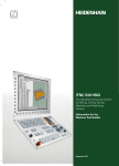
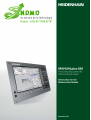
MANUALplus 620
Contouring Control with Inverters
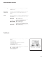
MANUALplus 620
• Contouring control for lathes with 2 axes, controlled spindle,
C axis and driven tools
• HEIDENHAIN inverter systems and motors
• 12.1-inch TFT flat-panel color display
• Hard disk
• Cycle programming for turning, drilling, boring and milling
operations
• smart.Turn programming for turning, boring drilling and milling
operations
• DIN programming for turning, boring, drilling and milling
operations
• Free ICP contour programming for turning and milling contours
• The MANUALplus supports simple tool holders (multipoint tools)
and tool turrets. The tool carrier can be located in front of or
behind the workpiece.
• The MANUALplus also supports vertical lathes.
BFT 131 operating panel
MC 420, CC 422
with modular inverter
System tests
Controls, motors and encoders from HEIDENHAIN are usually
integrated as components in larger systems. In these cases,
comprehensive tests of the complete system are required,
irrespective of the specifications of the individual devices.
Parts subject to
wear
In particular the following parts in controls from HEIDENHAIN are
subject to wear:
• Hard disk
• Buffer battery
• Fan
Standards
Standards (ISO, EN, etc.) apply only where explicitly stated in the
catalog.
2
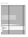
Contents
Page
Tables with Specifications, Machine Interfacing, User
Functions and Accessories
4
Control Systems
11
Cable Overviews
18
Technical Description
21
Overall Dimensions
38
Documentation
44
Service
45
Subject Index
47
Please refer to the page references in the tables with
the specifications.
The features and specifications described here apply for the
following control and NC software version:
MANUALplus 620
ID 548 328-01
Some of these specifications require particular machine
configurations. Please note also that, for some functions, a special
PLC program must be created by the machine manufacturer.
This catalog supersedes all previous editions, which thereby
become invalid.
Subject to change without notice
3
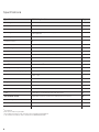
Specifications
Specifications
MANUALplus 620
Page
Main computer
MC 420
12
Controller unit
CC 422
14
Operating panel
• BFT 131 color flat-panel TFT display
• NC keyboard
15
Control systems
Inverter systems
*
Compact inverters
✔
*
Modular inverters
✔
*
Axes1) and spindles
22
Axes
2 closed-loop axes
22
C axis
With spindle motor or separate drive (option)
22
Driven tool
Option
23
Main spindle
Closed-loop
22
Speed2)
Max. 60 000 min–1
22
NC program memory
At least 15 GB on hard disk
Input resolution and display step
Linear axes
X axis: 0.5 µm (diameter: 1 µm)
Z axis: 1 µm
C axis
0,001°
Interpolation
Straight line
In 2 axes (max. ± 100 m)
**
Circle
In 2 axes (circle radius max. ± 999 m)
**
C axis
Interpolation of X and Z linear axes with the C axis
**
Axis feedback control
Digital drive control for synchronous and asynchronous motors
23
With following error
✔
24
With feedforward
✔
24
With jerk limiting
✔
25
1)
As ordered
On motors with two pole pairs
* For further information, refer to the brochure Inverters (ID 622 420-xx)
** For further information, refer to the brochure MANUALplus 620
2)
4
Specifications
Feed rate
MANUALplus 620
Maximum feed rate:
60 000 min–1
· screw pitch [mm]
No. of pole pairs in motor
Page
22
at fPWM = 5 000 Hz
Constant surface speed
✔
22
Input
mm/min or mm/revolution
22
Cycle times of main computer
MC 420
Block processing
3 ms
Position controller
3 ms
24
Cycle times of controller unit
CC 422
24
Speed controller
0.6 ms
24
Current controller
fPWM
3 333 Hz
4 166 Hz
5 000 Hz
6 666 Hz
8 333 Hz
10 000 Hz
Power supply
Inverter with logic unit: 3 x 400 V~
Color flat-panel display and PLC: 24 V–
Permissible temperature range
Operation: 0 °C to 40 °C
Storage: –35 °C to +65 °C
TINT
150 µs
120 µs
100 µs
75 µs
60 µs
50 µs
24
5
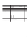
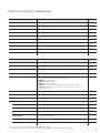
Machine Interfacing
Machine Interfacing
MANUALplus 620
Error compensation
Page
28
Linear axis error
✔
28
Nonlinear axis errors
✔
28
Backlash
✔
28
Hysteresis, reversal peaks
✔
28
Thermal expansion
✔
28
Stick-slip friction
✔
28
Integrated PLC
29
Program format
Statement list
29
Program input via the control
Via external USB keyboard
29
Program input via PC
✔
29
PLC memory
Hard disk
29
PLC cycle time
18 ms
29
PLC inputs, 24 V–
56 (expandable by PL)
PLC outputs, 24 V–
31 (expandable by PL)
Analog inputs ±10 V
3 (expandable by PL)
Analog outputs, ±10 V
6 (expandable by PL)
Inputs for thermistors
3 (expandable by PL)
PLC soft keys
✔
29
PLC positioning
✔
29
PLC basic program
✔
30
Encoder inputs
26
5
27
Incremental
1 VPP
27
Absolute
EnDat 2.1
27
6
27
Incremental
1 VPP
27
Absolute
EnDat 2.1
27
Position
Spindle speed
Commissioning and diagnostic aids
Integrated oscilloscope
6
31
✔
31
Machine Interfacing, Accessories
Machine Interfacing
MANUALplus 620
Page
Trace function
✔
31
Logic diagram
✔
31
Table function
✔
31
OLM (online monitor)
✔
32
Log
✔
31
Data Interfaces
34
Ethernet (100BaseT)
✔
34
RS-232-C/V.24
Can only be controlled via PLC
34
RS-422/V.11
Can only be controlled via PLC
34
USB 1.1
2
34
Accessories
MANUALplus 620
Page
Electronic handwheels
17
Up to two HR 180
✔
17
One HR 410 or
✔
17
One HR 130
✔
17
PLC input/output systems
Modular external PL 510 I/O systems consisting of
• Basic module with HEIDENHAIN PLC interface
PLB 510: for 4 I/O modules
PLB 511: for 6 I/O modules
PLB 512: for 8 I/O modules
• PLD 16-8: I/O module with 16 digital inputs and 8 digital outputs
• PLA 4-4: Analog module with 4 analog inputs for ±10 V and inputs for
PT 100 thermistors
16
USB hub
✔
34
DataPilot MP 620 programming station Control software for PCs for programming, archiving, and training
*
PLC basic program1)
✔
30
PLCdesignNT1)
PLC software developing environment
30
TNCremoNT
Data transfer software
35
TNCremoPlus
Data transfer software with “live” screen
35
TNCscopeNT1)
Software for data recording
31
DriveDiag1)
Software for diagnostics
32
TNCopt1)
Software for putting digital control loops into service
32
Software
* For further information, refer to the brochure MANUALplus 620
1)
For registered customers, these software products are available for downloading from the Internet.
7
Configuration
Modes of operation
Manual operation
Option
User functions
Standard
User Functions
•
•
Basic version: X and Z axis, spindle
0-2
Positionable spindle and driven tool
55+0-2 C axis and driven tool
•
Digital current and speed control
•
•
11
Teach-in
8
Program run
Programming
Cycle programming
9
8
17
17
Workpiece presetting
Definition of tool-change position
Definition of protection zone
Tool measurement by touching the workpiece
Tool measurement with a tool touch probe
Tool measurement with an optical gauge
•
•
•
•
8
8
8
8
8
8
8
8+55
8+55
8+55
8+55
8+55
8
8
8
8+9
Interactive contour
programming (ICP)
8
Sequential linking of fixed cycles, where each cycle is run immediately after input, or is
graphically simulated and subsequently saved.
All are possible in single-block and full-sequence modes
DIN PLUS programs
smart.Turn programming
Cycle programs
•
Setup functions
Manual slide movement through manual direction keys, intermediate switch or electronic
handwheels
Graphic support for entering and running cycles without saving the machining steps in
alternation with manual machine operation
Thread reworking (thread repair in a second workpiece setup)
8/9
8/9
8/9
8/9
8/9
8/9
8/9
Area clearance cycles for simple and complex contours, and contours defined with ICP
Contour-parallel area clearance cycles
Recessing cycles for simple contours, complex contours, and contours defined with ICP
Repetitions with recessing cycles
Recess turning cycles for simple and complex contours, and contours defined with ICP
Undercut and parting cycles
Threading cycles for single or multi-start longitudinal, taper or API threads
Cycles for axial and radial drilling, pecking and tapping operations with the C-axis
Thread milling with the C axis
Axial and radial milling cycles for slots, figures, single surfaces and polygons as well as for
complex contours defined with ICP for machining with the C axis
Helical slot milling with the C axis
Linear and circular patterns for drilling and milling operations with the C axis
Context-sensitive help graphics
Transfer of cutting values from technology database
Use of DIN macros in cycle programs
Conversion of cycle programs to smart.Turn programs
Contour definition with linear and circular contour elements
Immediate display of entered contour elements
Calculation of missing coordinates, intersections, etc.
Graphic display of all solutions for selection by the user if more than one solution is possible
Chamfers, rounding arcs and undercuts available as form elements
Input of form elements immediately during contour creation or by superimposition later
Changes to existing contours can be programmed
Programming
smart.Turn
programming
DIN PLUS
programming
Option
Standard
User functions
The basis is the unit, which is the complete description of a machining block (geometry,
technology and cycle data)
Dialog boxes divided into overview and detail forms
9
Fast navigation between the forms and input groups via the “smart” keys
9
Context-sensitive help graphics
9
Start unit with global settings
9
Transfer of global values from the start unit
9
Transfer of cutting values from technology database
9
Units for all lathe and recessing operations
9
9+55 Units for all milling and drilling operations with the C axis
9+55 Special units for activating/deactivating the C axis, subprograms and section repeats
Use of the contours described with ICP for lathe and milling operations
9
Use of the patterns described with ICP for drilling and milling patterns
9
Program verification graphics for workpiece blank and finished part
9
Turret assignment and other setup information in the smart.Turn program
9
Parallel programming
9
Parallel simulation
9
9
•
•
•
•
55
•
•
8/9
•
•
9
•
•
Test run graphics
Machining time analysis
•
•
Programming in DIN 66025 (ISO 6983) format
Expanded command format (IF...THEN...ELSE...)
Simple geometry programming (calculation of missing data)
Powerful machining cycles for area clearance, recessing, recess turning and thread machining
Powerful machining cycles for drilling and milling with the C axis
Subprograms
Programming with variables
Contour description with ICP
Program verification graphics for workpiece blank and finished part
Turret assignment and other setup information in the DIN PLUS program
Conversion of smart.Turn units into DIN PLUS command sequences
Parallel programming
Parallel simulation
•
•
•
•
Graphic simulation of the cycle process, or of the cycle, smart.Turn or DIN PLUS- program
Display of the tool paths as wire-frame or cutting-path graphics, special identification of the
rapid-traverse paths
Machining simulation (2-D material-removal graphic)
Side or face view, or 2-D view of cylindrical surface
Display of programmed contours
Shifting and magnifying functions
•
•
•
Calculation of machining time and idle machine time
Consideration of switching commands triggered by the CNC
Representation of single times per cycle or per tool change
9
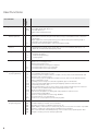
Overview
– Options
Option
number
Option
ID
Comment
0
1
Additional axis
354 540-01
353 904-01
Additional control loops 1 and 2
8
Software option 1
632 226-01
Cycle programming
• Contour description with ICP
• Cycle programming
• Technology database with 9 workpiece-material/tool-material combinations
9
Software option 2
632 227-01
smart.Turn
• Contour description with ICP
• Programming with smart.Turn
• Technology database with 9 workpiece-material/tool-material combinations
10*
Software option 3
632 228-01
Tools and technology
• Tool database expanded to 999 entries
• Technology database expanded to 62 workpiece-material/tool-material
combinations
• Support of multipoint tools
• Simple tool-life management
11*
Software option 4
632 229-01
Threads
• Thread recutting
• Handwheel superimposition during thread cutting
17*
Software option
TCH PROBE functions
632 230-01
Tool measurement
• Determining tool-setting dimensions with a touch probe
• Determining tool-setting dimensions with an optical gauge
42*
Software option
DXF-Import
632 231-01
DXF import
• Loading of DXF contours
55*
Software option
C-axis machining
633 944-01
C-axis machining
*Availability planned for end of 2009
10
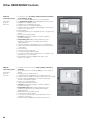
HEIDENHAIN Control Systems
The MANUALplus 620 lathe control from HEIDENHAIN includes various components,
which can be selected and combined to fit the application.
MANUALplus 620
Model
Page
Main computer
MC 420
12
Controller unit
CC 422
14
Operating panel
BFT 131
15
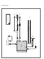
18
Connecting cables
Accessories
MC 420, CC 422
with compact inverter
PLC inputs/outputs
PL 510
16
Electronic handwheels
HR 410, HR 180 or HR 130
17
MC 420, CC 422
with modular inverter
11
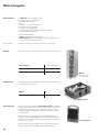
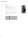
Main Computer
Main Computer
The MC 420 main computer includes:
• Processor (Celeron, 400 MHz)
• 512 MB RAM memory
• PLC
• Interface to the CC controller unit
• Interface to the control panel
• Interface to the handwheel
• Further interfaces (PLC expansion, Ethernet, USB,
RS-232-C/V.24, RS-422/V.11)
To be ordered separately:
• HDR hard disk with the NC software
• SIK component (System Identification Key) for enabling the
control loops and software options
Power supply
The main computer is powered over the CC controller unit.
MC 420
The MC 420 main computer features five position encoder inputs.
Position inputs
5 x 1 VPP or EnDat 2.1
Weight
4.2 kg
ID
515 929-02
MC 420
with 5 position
encoder inputs
HDR hard disk
The HDR hard disk is removable. It contains the NC software and
a slot for the SIK component.
HDR for
ID
MANUALplus 620
628 935-51
HDR hard disk
SIK component
The SIK component contains the NC software license for enabling
control loops and software options. It gives the main computer an
unambiguous ID code—the SIK number. The SIK component is
ordered and shipped separately. It must be inserted in a special
slot in the HDR.
Additional control loops and options can be enabled later by
entering a keyword. HEIDENHAIN provides the keyword, which is
based on the SIK number. When ordering, please indicate the SIK
number of your control.
When the keywords are entered in the control, they are saved in
the SIK component. This enables and activates the options.
12
SIK component
Master keyword
NC software license
For commissioning the MANUALplus 620, a master keyword can
be used that will unlock all options for a duration of two weeks.
After this period, the control loop options can only be activated
through the correct keyword. Should service become necessary,
the SIK component must be inserted in the replacement control
to enable all required options.
SIK with software license and enabling
for
ID
3 control loops
In preparation
3 control loops and cycle programming
option (option 8)
In preparation
3 control loops, cycle programming option
(option 8), smart.Turn (option 9) and C axis
(option 55)
530 005-53
Additional axes
Software options
Option
number
ID
1st additional axis
(4th control loop)
0
354 540-01
2nd additional axis
(5th control loop)
1
353 904-01
The features of the MC 420 can also be adapted with options
retroactively to meet new requirements. These options are
described on page 10. They are enabled by entering keywords
based on the SIK number, and are saved in the SIK component.
Please indicate your SIK number when ordering new options.
13
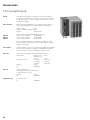
Controller Unit
Controller unit
The CC 422 controller unit includes:
• Speed controller
• Current controller
• Interfaces to the UM 1xx, UR 2xx, and UE 2xx power modules
(PWM outputs)
• Interfaces to the shaft speed encoders
• Interfaces for power supply for controller unit and main
computer (supply via UVR 1xx D, UE 2xx D or UR 2xx)
CC 422
The CC 422 is available with max. 6 digital control loops.
The number of enabled control loops is saved in the SIK (see Main
Computer).
The CC 422 controller unit is combined with the MC 420 main
computer. The position controllers and position encoder inputs are
located on the MC 420 main computer (version with 5 position
encoder inputs).
14
CC 422
Max. 6 digital control loops
Speed inputs
6 x 1 VPP or EnDat 2.1
PWM outputs
6
Weight
4.0 kg
ID
359 651-xx
CC 422
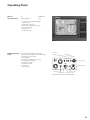
Operating Panel
BFT 131
Operating Panel
ID
Weight (approx.)
583 683-01
3 kg
• 12.1-inch color flat-panel display
(1024 x 768)
• Operating mode keys
• Horizontal and vertical soft keys
• Numeric keypad
• Editing keys
• smart.Turn keys
BFT 131
Machine operating
panel
The machine tool builder designs the
machine operating panel. It should contain
the following components:
• Handwheels
• Axis-direction buttons or joystick
• Emergency-stop button
• Feed rate override
• Spindle override
• Cycle keys
• Spindle keys
Handwheel
resolution
Cycle start
Cycle stop
Tool change
Handwheel X
Coolant
Emergency stop
Spindle start/stop
Handwheel Z
Spindle jog +/–
Spindle override
Feed rate override
Rapid traverse Axis-direction keys
Proposal for a machine operating panel
15
Accessories
PLC Inputs/Outputs
PL 510
If the PLC inputs/outputs of the MC do not suffice, additional
PL 510 PLC input/output units can be connected. These external
modular I/O systems consist of a basic module and one or more
input/output modules.
Basic modules
Basic modules are available for 4, 6 or 8 I/O modules. They are
mounted on standard NS 35 rails (DIN 46 227 or EN 50 022).
Supply voltage
24 V–
Power consumption (approx.) 20 W
Weight
0.36 kg (bare)
PLB 510
PLB 511
PLB 512
Basic modules with HEIDENHAIN PLC interface
Slots for 4 I/O modules
ID 358 849-01
Slots for 6 I/O modules
ID 556 941-01
Slots for 8 I/O modules
ID 557 125-01
Up to four PLB 510 and up to two PLB 511 or PLB 512 can be
connected to the control. The maximum cable length to the last
PLB 51x is 30 meters.
I/O modules
The I/O modules consist of one module with digital inputs/outputs
and one analog module. For partially assembled basic modules,
the unused slots must be occupied by an empty housing.
PLD 16-8
I/O module with 16 digital inputs and 8 digital outputs
Total current
Simultaneity factor:
Weight
ID
PLA 4-4
Empty housing
16
Outputs 0 to 7:
Outputs 0 to 3,
or 4 to 7:
2 outputs:
4 outputs:
8 outputs:
0.2 kg
360 916-01
Analog module with
4 analog inputs for PT 100 thermistors
4 analog inputs for ± 10 V
Weight
ID
0.2 kg
366 423-01
For unused slots
ID
383 022-01
†4A
†2A
2 A each
1 A each
0.5 A each
PL 510
Electronic Handwheels
The standard MANUALplus 620 supports the use of electronic
handwheels.
The following handwheels can be installed:
• For connection to position inputs
Up to two HR 180
• For connection to the handwheel input
One HR 410 portable handwheel, or
One HR 130 panel-mounted handwheel
Any combination is possible: cycle machines typically use two
HR 180 and—depending on the needs—an HR 140 or simply an
HR 130 for CNC machines.
Function
• Incremental movement of the slide:
1 µm/10 µm/100 µm per increment
• The handwheels with detent have 100 stops per revolution
• Positioning the slide to the starting position of MANUALplus
cycles
• Fine adjustment of tool position
HR 180
Panel-mounted handwheel with ergonomic control knob for
connection to a position encoder input.
Weight (approx.)
HR 180 with detent
HR 130
Panel-mounted handwheel with ergonomic control knob for
connection to the handwheel input.
It is connected to the logic unit directly or via extension cable.
Weight (approx.)
HR 130 without detent
HR 130 with detent
HR 410
0.7 kg
ID 540 940-08
0.7 kg
ID 254 040-05
ID 540 940-01
Portable handwheel for connection to the handwheel input with
• Keys for the selection of 5 axes
• Traverse direction keys
• Keys for three preset feed rates (PLC function)
• Actual-position-capture key
• Three keys with machine functions (see below)
• Two permissive buttons (24 V)
• Emergency stop button (24 V)
• Magnetic holding pads
• Weight approx. 1 kg
All keys are designed as snap-on keys and can be replaced by keys
with other symbols.
HR 410 (NC start/stop, spindle start; for PLC basic program)
without detent
ID 296 469-55
with detent
ID 535 220-05
HR 410 (spindle right/left/stop)
without detent
ID 296 469-54
Connecting cable (spiral)
to HR 410 (3 m)
HR 410 / MC 422 adapter cable
Dummy plug for emergency stop circuit
ID 312 879-01
ID 296 466-xx
ID 271 958-03
17
18
Axes: 60m
EnDat interface
VL
340 302-xx
Axes + spindle: 60m
Axes + spindle: 30m
1 VPP
Voltage controller 5 V
370 224-01
VL
340 302-xx
X149
X69
336 376-xx
Axes: 15m
289 440-xx
289 440-xx
332 115-xx
332 115-xx
Position inputs
X1 ... X5
Analog output
PLC I/0
X8
244 005-xx
VL
263 955-xx
263 954-xx
Machine
operating panel
X41/X42
X46
X15 ... X20
MC 420
CC 422
X45
VL
263 955-xx
263 954-xx
X51 ... X62
Voltage controller 5 V
370 226-01
VL
336 847-xx
VL
336 847-xx
353 545-xx
20m
BFT 131
BFT 1xx
583 683-01
Speed inputs
40m
370 747-xx
309 783-xx
310 199-xx
298 429-xx
298 430-xx
244 005-xx
263 954-xx
Voltage controller 5 V
370 225-01
VL
323 897-xx
VL
323 897-xx
Terminal box
251 249 01
20m
37-pin male connector
315 650-07
290 109-xx
290 110-xx
15-pin male connector
315 650-03
RCN
LC
1 VPP
9m
1 VPP
1 VPP
} max. 9m
15m
369 124-xx
369 129-xx
max.11m
40m
Housing must be mounted
LC
RCN
60m
60m
28.06.2007
VL: Extension cable
for separation points with connecting cable
for extending existing connecting cable
Cable Overviews
Control Systems
X69
X51 ... X62
See Motors catalog
for power cable to motor
325 816-xx
250 479-07 ... -16
250 479-07 ... -16
UV 130
15m
325 817-xx
UM 1xx
325 816-xx
250 479-07 ... -16
X69
X51 ... X62
CC 422
See Motors catalog
for power cable to motor
250 479-07 ... -16
UM 1xx UM 1xx
Modular inverter (non-regenerative)
15m
3 Vac power supply
PW 210
PW 210
CC 422
Compact inverter (non-regenerative)
UE 2xx B
3 Vac power supply
Line filter
EPCOS xx
Three-phase
ac capacitor
348 993-01
(if needed)
KDR 1xx
15m
Three-phase
ac capacitor
348 993-01
3-phase~ power
3 Vac power supply
Line filter
EPCOS 35 A
KDR 120
X69
X51 ... X62
See Motors catalog
for power cable to motor
325 816-xx
250 479-07 ... -16
250 479-07 ... -16
CC 422
15m
See Motors catalog
for power cable to motor
325 816-xx
325 817-xx
250 479-07 ... -16
250 479-07 ... -16
UVR UM 1xx UM 1xx UM 1xx UM 1xx UP 110
1xx D
Modular inverter (regenerative)
UR 2xx
Compact inverter (regenerative)
X69
X51 ... X62
CC 422
Inverter Systems
19
20
310 197-xx
X12
X141,
X142
X27
X28
624 775-xx
354 770-xx
X26
Touchprobe
MC 420
X1 ... X5
X147
X23
5m
371 046-xx
4 x max.
PL 510
25m
371 046-xx
USB hub
582 884-01
VL 281 429-xx
30m
Ethernet 10Base2
Ethernet 10Base2 (transposed)
VL 310 199-xx
296 466-xx
1 VSS
312 879-01 3 m
HR 180
540 940-08
HR 410
296 469-xx
Ethernet network
50m
HR 130
540 940-xx
08.08.2007
Connector housing must be mounted
VL: Extension cable
for separation points with connecting cable
for extending existing connecting cable
Accessories
MANUALplus 620
The Contouring Control for Lathes and Cycle Lathes
The MANUALplus 620 for cycle lathes
• Conceived for general repairs, thread repairs, single parts and
short production runs
• Supports action-oriented machining
• Quickly learned—requires minimum training time
• Supports boring, drilling and milling operations on the face and
lateral surface
• Features a wide machining spectrum, from simple turned parts
to complex workpieces
The MANUALplus 620 for CNC lathes
• Conceived for medium-sized and large production runs
• Programming via smart.Turn and/or DIN PLUS
• smart.Turn is quickly learned and requires very little training time
• Supports boring, drilling and milling operations on the face and
lateral surface
• Features a wide machining spectrum, from simple turned parts
to complex workpieces
21
Technical Description
Axes
The MANUALplus 620 is a contouring control for manual lathes
with one spindle and a compound rest (X and Z) for tool movement.
The MANUALplus supports both horizontal and vertical lathes.
Display and
programming
Feed rate in
• mm/min
• mm/revolution
• Feed rate override: 0 to 150%
• Maximum feed rate at fPWM = 5 000 Hz:
60 000 min–1
· screw pitch [mm]
No. of pole pairs in motor
Traverse range
–99 999.9999 to +99 999.9999 [mm]
The machine tool builder defines the traverse range. It is also
possible for the operator to limit the traverse range if he wishes
to reduce the working space (with software limit switches).
A protection zone for the spindle (Z–) can also be specified.
Tool carriers
The MANUALplus 620 supports simple tool holders (multipoint
tools) and tool turrets. The tool carriers can be located in front of or
behind the workpiece.
Main Spindle
For machines featuring a higher level of automation, you can
position the spindle or switch to C-axis operation.
Display and
programming
Spindle speed:
• Constant shaft speed: 1 to 99 999 rpm
• Constant surface speed: 1 to 9 999 m/min
Spindle positioning
Input resolution and display step: 0.001°
Spindle override
50 to 150%
Maximum speed
nmax
=
fPWM
NPP
= PWM frequency in Hz
= Number of pole pairs
fPWM · 60 000 min–1
NPP · 5 000 Hz
Speed limiting
• The MANUALplus monitors the actual speed.
• Speed limiting can be adjusted via parameter and in the
feed rate/spindle/tool menu.
Gear stages
A specific parameter can be defined for each gear range. The gear
is switched via the PLC.
C-axis operation
For milling, drilling and boring cycles, either the spindle is switched
to C-axis operation or a separate C-axis drive is activated.
Input resolution and display step: 0.001°
22
Driven Tool
The driven tool is used for drilling and tapping holes as well as for
milling in M19 or C-axis operation. Programs for the driven tool can
be input in manual operation, via cycles with smart.Turn or in the
DIN editor.
Display and
programming
Speed of the driven tool:
• Constant shaft speed: 1 to 99 999 rpm
• Constant surface speed: 1 to 9 999 m/min
Speed limiting
• The MANUALplus monitors the actual speed.
• Speed limiting can be adjusted via parameter and in the
feed rate/spindle/tool menu.
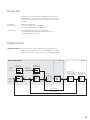
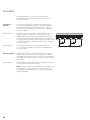
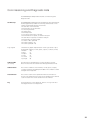
Digital Control
Integrated inverters Position controllers, speed controllers, current controllers and
inverters are integrated in the control. HEIDENHAIN synchronous
and asynchronous motors are connected to the MANUALplus 620.
Servo drive control
Nominal
velocity
Velocity
feedforward
Inverter
Nominal
acceleration
Position
controller
Nominal
position
Acceleration
feedforward
Current
controller
Speed
controller
Nominal
speed
Machine
Power stage
Motor with
rotary encoder
for shaft speed
and rotor position
Machine slide
with linear or
angle encoder
Nominal
current
Actual current
Actual speed
Actual position
23
Axis feedback
control
The MANUALplus 620 operates with feedforward control.
Operation with
following error
(servo lag)
The term “following error” denotes the distance between the
momentary nominal position and the actual position of the axis.
The velocity is calculated as follows:
v = kv · sa
v
kv
sa
= velocity
= loop gain
= following error
Operation with
Feedforward control means that the speed and the acceleration
feedforward control are preset according to the machine, while taking the jerk limiting
into account. Together with the values calculated from the
following error, it forms the nominal value. In this way, the
following error becomes very small (in the range of a few µm).
The feedforward is adjustable from 0 to 100% via a machine
parameter.
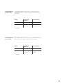
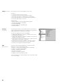
The position controller cycle time is the time interval in which the
actual position value is compared to the calculated nominal
position value.
The speed controller cycle time is the time interval in which the
actual speed value is compared to the calculated nominal speed
value. The cycle time for the current controller is defined as the
time interval during which the actual current value is compared to
the calculated nominal current value.
MC 420
CC 422
24
Position
controller
Speed
controller
Current
controller
3 ms
0.6 ms
0.1 ms
Position
Control loop cycle
times
Time
Fast Machining
Look-ahead
The MANUALplus 620 calculates the geometry ahead of time in
order to adjust the feed rate. In this way directional changes are
detected in time to accelerate or decelerate the appropriate NC
axes.
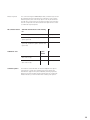
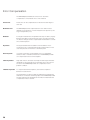
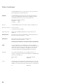
Jerk Limiting
Jerk
The derivative of acceleration is referred to as jerk.
A linear change in acceleration causes a jerk step. This jerk
causes oscillations, and leads to contour damage.
Jerk limiting
To prevent machine oscillations, the jerk is limited to attain
optimum path control. The MANUALplus 620 machines smooth
surfaces at the highest possible feed rate, and yet keeps the
contour accurate. The machine manufacturer sets the permissible
tolerance via parameter.
v
a
Jerk smoothing
The jerk is smoothed by a nominal position value filter. The
MANUALplus 620 machines smooth surfaces at the highest
possible feed rate. The machine manufacturer sets the permissible
tolerance via parameter.
j
t
t
t
25
Encoders
For speed and position control of the axes and spindle,
HEIDENHAIN offers both incremental as well as absolute
measuring systems.
Incremental
encoders
Incremental encoders have as measuring standard a grating
consisting of alternate lines and spaces. Relative movement
between the scanning head and the scale causes output of
sinusoidal scanning signals. The measured value is calculated
from these signals.
Reference mark
When the machine is switched on, the machine axes need to
traverse a reference mark for an accurate reference to be
established between measured value and machine position. For
encoders with distance-coded reference marks, the maximum
travel until automatic reference mark evaluation for linear encoders
is only 20 mm or 80 mm, depending on the model, or 10° or 20°
for angle encoders.
Output signals
Incremental encoders with sinusoidal output signals with
» 1 VPP levels are suitable for connection to HEIDENHAIN
numerical controls.
Absolute encoders
With absolute encoders, the position information is mapped in
several coded tracks. Thus, an absolute reference is available
immediately after switch-on. There is no need to scan a reference
mark. Additional incremental signals are output for highly dynamic
control loops.
EnDat interface
The MANUALplus 620 is fitted with the serial EnDat 2.1 interface
for the connection of absolute encoders.
Note: The EnDat interface on HEIDENHAIN encoders differs in its
pin assignment from the interface on Siemens motors with
integrated absolute ECN/EQN rotary encoders. Special adapter
cables are available.
26
Encoder inputs for
position control
Incremental and absolute linear, angle or rotary encoders from
HEIDENHAIN can be connected to all position encoder inputs of
the MC 420.
Inputs
Signal level/
Interface1)
Input frequency1)
Incremental
» 1 VPP
33 kHz/350 kHz
Absolute
EnDat 2.1
» 1 VPP
–
33 kHz/350 kHz
1)
Encoder inputs for
speed control
Switchable
Incremental and absolute rotary encoders from HEIDENHAIN can
be connected to all speed encoder inputs of the CC 422.
Inputs
Signal level/
1)
Interface
Input frequency
Incremental
» 1 VPP
350 kHz
Absolute
EnDat 2.1
» 1 VPP
–
350 kHz
1)
Switchable
27
Error Compensation
The MANUALplus 620 features functions for automatic
compensation of mechanical errors of the machine.
Linear error
Linear error can be compensated over the entire travel range for
each axis.
Nonlinear error
The MANUALplus 620 compensates axis error and error that
depends on the positions of other axes (ball screw pitch error, axis
sag, misaligned axes, etc.).
Backlash
For length measurements via spindle and rotary encoders, the play
between the table movement and the rotary encoder movement
on direction changes can be compensated. This backlash is outside
the controlled system.
Hysteresis
The hysteresis between the table movement and the motor
movement is also compensated in length measurements. In this
case the hysteresis is within the controlled system.
Reversal peaks
In circular movements, reversal peaks can occur at quadrant
transitions due to mechanical influences. The MANUALplus 620
can compensate for these reversal peaks.
Stick-slip friction
High static friction can lead to stick-slip: the slide stops and starts
repeatedly for short periods at low feed rates. This is also known
as stiction. The MANUALplus 620 can compensate for this
problem condition.
Thermal expansion
To compensate thermal expansion, the machine expansion
behavior must be known.
The temperature can be recorded via temperature measurement
thermistors connected to the analog inputs of the MANUALplus 620.
The PLC evaluates the temperature information and transfers the
compensation value to the NC.
28
Integrated PLC
The PLC program is created by the machine manufacturer either
with the PLC development software PLCdesignNT (accessory) or
at the control with an external PC keyboard with a USB
connection.
Machine-specific functions are activated and monitored via the
PLC inputs/outputs. The number of PLC inputs/outputs required
depends on the complexity of the machine.
PLC expansion
If the PLC inputs/outputs of the MC 420 do not suffice, the
external PL 510 PLC input/output system can be connected.
Rated operating
current per output
Logic unit:
0.15 A
(For PL 5xx see PLC Inputs/Outputs)
PLC programming
Format
Statement list
Memory
• PLC program: on hard disk
• Process memory: 512 KB RAM
• Data memory: 124 KB RAM
Cycle time
18 ms, adjustable
Instruction set
•
•
•
•
•
•
•
•
•
•
•
•
•
•
Bit, byte and word commands
Logical operations
Arithmetic instructions
Comparisons
Parenthetic calculations
Jump commands
Subprograms
Stack operations
Submit programs
999 timers
48 counters
Comments
PLC modules
100 strings
PLC soft keys
The machine manufacturer can display his own PLC soft keys in
the vertical soft-key row on the screen.
PLC positioning
All closed-loop axes can be positioned via the PLC. PLC positioning
of the NC axes cannot be superimposed on NC positioning.
PLC axes
Axes can be controlled by the PLC. They are programmed via
M functions or OEM cycles. The PLC axes are positioned
independently of the NC axes.
29
PLCdesignNT
(accessory)
PC software for PLC program development.
The PC program PLCdesignNT can be used for easy creation of
PLC programs. Comprehensive examples of PLC programs are
included.
Functions:
• Easy-to-use text editor
• Menu-guided operation
• Programming of symbolic operands
• Modular programming method
• “Compiling” and “linking” of PLC source files
• Operand commenting, creation of a documentation file
• Comprehensive help system
• Data transfer between personal computer and
MANUALplus 620
• Creation of PLC soft keys
PC requirements:
• Operating system Windows 98/NT/2000/ME/XP
• Compatible computer, Pentium 133 or higher
• At least 32 MB RAM
• Minimum 20 MB free memory on the hard disk
• At least VGA
• Serial interface; Ethernet interface recommended
• Internet Explorer 4.01 or higher
PLC basic program
The PLC basic program serves as a basis for adapting the
MANUALplus 620 to the requirements of the respective machine.
Registered customers can download it from the Internet.
The following functions are covered by the PLC basic program:
• Controlling all axes
• Positioning the axes after the reference run
• Clamped axes
• Homing the axes, reference end positions
• Temperature compensation of the axes
• Feed rate control
• Controlling and orienting the spindle
• Spindle brake
• Gear switching via M functions
• C axis via main drive
• C axis via separate drive1)
• PLC soft keys
• Displaying and managing PLC error messages
• Hydraulic control1)
• Hydraulic chuck1)
• Electronic handwheels
• Controlling the coolant system1)
• Handling of M and G functions
• Lubrication1)
• Chip conveyor1)
• Door control1)
• Tool change for multipoint tools1)
• Positioning of the tool turret with three-phase motor1)
1)
30
Basic functions are implemented
Commissioning and Diagnostic Aids
The MANUALplus 620 provides internal commissioning and
diagnostic aids.
Oscilloscope
The MANUALplus 620 features an integrated oscilloscope. Both X/t
and X/Y graphs are possible. The following characteristic curves
can be recorded and saved in six channels:
• Actual value of axis feed rate
• Nominal value of axis feed rate
• Contouring feed rate
• Actual position
• Nominal position
• Servo lag of the position controller
• Nominal values for speed, acceleration and jerk
• Actual values for speed, acceleration and jerk
• Nominal value of analog output
• Content of PLC operands
• Encoder signal (0° – A)
• Encoder signal (90° – B)
Logic signals
Simultaneous graphic representation of the logic states of up to
16 operands (markers, words, inputs, outputs, counters, timers)
• Marker
(M)
• Input
(I)
• Output
(O)
• Timer
(T)
• Counter
(C)
• IpoLogik
(X)
TNCscopeNT
(accessory)
PC software for transferring the oscilloscope files to the PC.
Note: The trace files are saved in the TNCscopeNT data format.
Table function
The current conditions of the markers, words, inputs, outputs,
counters and timers are displayed in tables. The conditions can be
changed via the keyboard.
Trace function
The current content of the operands and the accumulators is
shown in the statement list in each line in hexadecimal or decimal
code. The active lines of the statement list are marked.
Log
For the purposes of error diagnosis, there is one log for all error
messages and one for all keystrokes.
31
TNCopt (accessory)
PC software for commissioning digital control loops
Functions:
• Commissioning the current controller
• (Automatic) commissioning of the speed controller
• (Automatic) optimization of sliding-friction compensation
• (Automatic) optimization of the reversal-spike compensation
• (Automatic) optimization of kV factor
Requirements:
• Windows 95/98 or NT 4.0 or 2000 operating system
• At least VGA—XGA recommended
• At least 16 MB RAM
• At least 15 MB of free hard-disk space
• Ethernet interface
DriveDiag
(accessory)
The DriveDiag software for PCs enables the service technician to
make a simple and fast diagnosis of the drives. It also permits the
display and evaluation of the electronic ID labels.
The following diagnostic functions are available:
• Reading and displaying the electronic ID labels of QSY motors
with EQN 1325 or ECN 1313
• Reading and displaying the electronic ID labels of the UVR 1xx D
and UM 1xx D inverter modules
• Displaying and evaluating the internal control conditions and the
status signals of the inverter components
• Displaying the analog values available to the drive controller
• Automatic test for proper function of motors and inverters
• Automatic test of position and speed encoders
OLM
Online monitor
The online monitor (OLM) supports the commissioning and
diagnosis of control components through:
• Display of control-internal variables for axes and channels
• Display of controller-internal variables
• Display of hardware signal states
• Various trace functions
• Activation of spindle commands
• Enabling control-internal debug outputs
The online monitor is a component part of the control and is called
over a code number.
32
Monitoring Functions
During operation, the MANUALplus 620 monitors:
• Amplitude of the encoder signals
• Edge separation of the encoder signals
• Absolute position for encoders with distance-coded
reference marks
• Current position (servo lag monitoring)
• Actual path traversed (movement monitoring)
• Position deviation at standstill
• Nominal speed value
• Checksum of safety-related functions
• Supply voltage
• Buffer battery voltage
• Operating temperature of the MC and CPU
• Running time of the PLC program
• Motor current
• Motor temperature
• Temperature of power module
• DC-link voltage
Hazardous errors trigger an EMERGENCY STOP message that is
sent to the external electronics via the control-is-ready output, and
the axes are brought to a stop. The correct connection of the
MANUALplus 620 into the machine’s EMERGENCY STOP loop is
checked when the control system is switched on.
In the event of an error, the MANUALplus 620 displays a message
in plain language.
33
Data Interfaces
The MANUALplus 620 is connected to PCs, networks and other
data storage devices via data interfaces.
Ethernet
The MANUALplus 620 can be interconnected via the Ethernet
interface. The MANUALplus 620 features a 100BaseT Ethernet
(Twisted Pair Ethernet) connection to the data network.
Maximum transmission distance:
Unshielded 100 m
Shielded
400 m
Protocol
The MANUALplus 620 communicates using the TCP/IP protocol.
Network connection
• NFS file server
• Windows networks (SMB)
Data transfer rate
Approx. 40 to 80 Mbps (depending on file type and network
utilization)
RS-232-C/V.24
Data interface according to DIN 66 020 or EIA standard RS-232-C.
Maximum transmission distance:
20 m
RS-422/V.11
Data interface according to EIA standard RS-422.
Maximum transmission distance:
1 km
The V.24 and V.11 interfaces can only be addressed by the PLC.
USB
The two USB interfaces are available for connecting standard
storage media. They must not be loaded with a total supply current
greater than 0.5 A. The maximum cable length for external USB
units is 5 m without an amplifier. For lengths from 6 m, USB
connecting cables with an integrated amplifier are required.
USB hub
If you need further USB ports or if the supply current is not
sufficient, a USB hub is required. The USB hub from HEIDENHAIN
offers four free USB ports.
Power supply:
ID
Cover
The USB hub can be installed in the operating panel in such a way
that two USB ports can be accessed from the outside. An optionally
available cover can be used to protect the ports from contamination.
ID
34
24 V– / max. 300 mA
582 884-01
508 921-01
Software for Data Transfer
TNCremoNT
(accessory)
This PC software package helps the user to transfer data between
the PC and the MANUALplus 620. The software is available free of
charge on the HEIDENHAIN home page in the Services/Software
area.
Functions:
• Data transfer
• File management
• Data backup
• Reading out the log
• Screen content, reading out
• Managing more than one machine
Requirements:
• Operating system Windows 95/98/ME/NT/2000/XP
• At least 10 MB free hard-disk space
• Ethernet interface
TNCremoPlus
(accessory)
In addition to the features you are already familiar with from
TNCremoNT, TNCremoPlus can also transfer the current content of
the control’s screen to the PC (“live screen”). This makes it very
simple to monitor the machine.
ID
340 447-xx
35
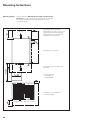
Mounting Instructions
Mounting attitude
When installing the MC 420, CC 422, UV(R) 1xx, UM xxx and
UE 2xx, B take note of the minimum spacing, space needed for
servicing, and the appropriate length and location of the
connecting cables.
Leave space for air circulation!
Temperatures of > 150 °C may occur
with the UE 21x B with integrated
braking resistor; do not mount any
temperature-sensitive parts!
Air out
Leave space for servicing!
Leave space for air circulation and
servicing!
Air in
*) Leave space for
exchanging the
HDR hard disk
Leave space for servicing and
connecting cables!
UV(R), UE, UM
36
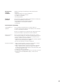
MC 42x, CC 42x
Mounting and
electrical
installation
Keep the following in mind during mounting and electrical
installation:
• National regulations for power installations
• Interference and noise immunity
• Conditions of operation
• Mounting attitude
Degrees of
protection
The following components fulfill the requirements for IP 54 (dust
protection and splash-proof protection):
• Visual display unit (when properly installed)
• Keyboard unit (when properly installed)
• Handwheel
Electromagnetic compatibility
Intended place of
operation
The unit fulfills the requirements for a Class A device in
accordance with the specifications in EN 55 022, and is intended
for use in industrially zoned areas.
Protect your equipment from interference by observing the rules
and recommendations specified in the Technical Manual.
Likely sources of
interference
Noise is mainly produced by capacitive and inductive coupling
from electrical conductors or from device inputs/outputs, such as:
• Strong magnetic fields from transformers or electric motors
• Relays, contactors and solenoid valves
• High-frequency equipment, pulse equipment and stray magnetic
fields from switch-mode power supplies
• Power lines and leads to the above equipment
Protective measures
• Keep a minimum distance of 20 cm from the MC, CC and its
leads to devices that carry interference signals.
• Keep a minimum distance of 10 cm from the MC, CC and its
leads to cables that carry interference signals. For cables in
metallic ducting, adequate decoupling can be achieved by using
a grounded separation shield.
• Shielding according to EN 50 178
• Use potential compensating lines with a cross section of 6 mm2
• Use only genuine HEIDENHAIN cables, connectors and
couplings.
37
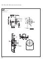
Overall Dimensions
MC 420
CC 422
Dimensions in mm
Tolerancing ISO 8015
ISO 2768 - m H
< 6 mm: ±0.2 mm
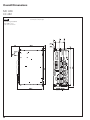
38
MC 420 / 5 position encoder inputs
CC 422 / 6 control loops
BFT 131
Dimensions in mm
Tolerancing ISO 8015
ISO 2768 - m H
< 6 mm: ±0.2 mm
410
12
76+1
5+1
8
386±0.2
¬ 5.5
¬ 10
¬ 8+1
274±0.2
290
M5
1
2
15x45°
274±0.2
f 270+1
4x M5
(7)
0.5
m
386±0.2
f 400+1
f = Cutout in machine panel
m = Mounting surface
39
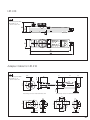
HR 130, HR 180 with Control Knob
Dimensions in mm
Tolerancing ISO 8015
ISO 2768 - m H
< 6 mm: ±0.2 mm
0.08 A
36.7±0.5
10
12
0°
¬ 0.08 B
C
0.01
¬ 10 0.02
e
20±0.5
0.03 A
¬ 58
¬ 36f8
e
A
¬ 56
3x
B
¬ 48
¬6
4.4
M3 x 5
3x
¬ 0.25 C
40
HR 410
Dimensions in mm
Tolerancing ISO 8015
ISO 2768 - m H
< 6 mm: ±0.2 mm
Adapter Cable for HR 410
Dimensions in mm
M5
64
14
38
23
Ø 36
¬ 55
32x15
Tolerancing ISO 8015
ISO 2768 - m H
< 6 mm: ±0.2 mm
Mounting cutout for wall thickness S†4
4
Mounting cutout for wall thickness S>4
19
44
¬ 34
44
32
M4
¬ 5.5
S
¬ 37
S
41
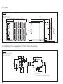
PL 510
Dimensions in mm
Tolerancing ISO 8015
ISO 2768 - m H
< 6 mm: ±0.2 mm
148
PL 510/550: 139, PL 511: 183, PL 512: 227
132
95
3.25
51
X2
135
X1
X3
78
Line Drop Compensator for EnDat Interface
Dimensions in mm
Tolerancing ISO 8015
ISO 2768 - m H
< 6 mm: ±0.2 mm
34
64
12.5
29
46
58
¬5
¬9
36
20
*)
15
32
127
*) Variant 03
Connection for temperature sensor
42
USB Hub
Dimensions in mm
17.5
40
Tolerancing ISO 8015
ISO 2768 - m H
< 6 mm: ±0.2 mm
Cover (accessory)
50
28
M3
109
80
100±0.2
A
70±0.2
m
¬ 3.4
50±0.2
¬ 3.5
19
17.5
37
30±0.2
68
¬ 2.5
93.2
A
180°
42
60±0.2
m = Cutout for mounting
USB Extension Cable with Hubs
Dimensions in mm
Tolerancing ISO 8015
ISO 2768 - m H
< 6 mm: ±0.2 mm
L
1000...5000
n x 5000
5000
USBB
¬ 20
USBA
115
n = 0 ... 4
L = Ordering length
43
Documentation
The following are supplied with a control system:
• 1 MANUALplus 620 User’s Manual
• 1 MANUALplus 620 Pilot (brief programming guide;
in preparation)
This documentation must be ordered separately in the language
required.
Further documentation is available from HEIDENHAIN.
Technical
documentation
• HEIDENHAIN Technical Manual for MANUALplus 620
in English or German
ID 634 863-xx
• Technical Manual for Inverter Systems and Motors
ID 208 962-xx
The Technical Manuals are in loose-leaf format in a ring binder.
Supplementary issues with update information and replacement
sheets are sent when the software or hardware is updated.
User
documentation
• MANUALplus 620 User’s Manual
Other
documentation
•
•
•
•
44
Motors brochure
MANUALplus 620 brochure
DataPilot MP 620 CD-ROM
Inverter Systems brochure
ID 634 864-xx
ID 208 893-xx
ID 634 865-xx
In preparation
ID 622 420-xx
HEIDENHAIN Service
Technical support
HEIDENHAIN offers the machine manufacturer technical support
to optimize the adaptation of the MANUALplus to the machine—
including on site.
Replacement
control system
In the event of a fault, HEIDENHAIN guarantees the rapid supply
of a replacement control system (usually within 24 hours in
Europe).
Hotline
Our service engineers are naturally at your disposal by telephone if
you have any questions on the interfacing of the control or in the
event of faults.
{ +49 (8669) 31-3101
E-mail: [email protected]
PLC programming { +49 (8669) 31-3102
E-mail: [email protected]
NC programming { +49 (8669) 31-3103
E-mail: [email protected]
Measuring systems { +49 (8669) 31-3104
E-mail: [email protected]
Lathe controls
{ +49 (8669) 31-3105
E-mail: [email protected]
TNC support
Seminars
HEIDENHAIN provides technical customer training in the following
subjects:
•
•
•
•
•
•
NC programming
PLC programming
MANUALplus 620 mounting and commissioning
MANUALplus 620 service
Encoder service
Special training for specific customers
For more information on dates, registration, etc. call in Germany:
{
+49 (8669) 31-2293 or 31-1695
|
+49 (8669) 31-1999
E-mail: [email protected]
www.heidenhain.de
45
Other HEIDENHAIN Controls
iTNC 530
contouring control
Information:
brochure
iTNC 530
TNC 320
contouring control
Information:
brochure
TNC 320
46
• Contouring control for milling, drilling and boring machines,
and machining centers
• Max. 11 closed-loop axes and servo-controlled spindle
• For digital drive control with HEIDENHAIN inverter systems
• Flat-panel color display (15-inch)
• Keyboard unit with alphanumeric keys
• Program memory on integrated hard disk
• Program input with smarT.NC in HEIDENHAIN conversational
format or according to ISO
• DXF file import
• External programming on CAD/CAM systems or programming
stations
• FK free contour programming
• User aids: Programming graphics, verification graphics,
program-run graphics
• Programming aids: Milling, drilling and boring cycles,
parametric programming, coordinate transformation,
subprogramming
• Five-axis machining with TCPM and 3-D tool compensation
• Tilted working plane with PLANE function and machining with
a rotary table
• HSC machining
• Collision monitoring (optional)
• Tool, datum, preset and pallet tables
• Connection of HR electronic handwheels, TS workpiece touch
probes and TT tool touch probes
• Data interfaces: Ethernet 100BaseT; RS-232-C / V.24;
RS-422 / V.11; USB 1.1
• Compact contouring control for milling, drilling and boring
machines
• Three (optionally four) closed-loop axes plus one closed-loop
spindle
• Analog speed command interface
• Integrated keyboard and flat-panel color display (15-inch)
• Program memory: 10 MB on Compact Flash memory card (CFR)
• Program input in HEIDENHAIN conversational language,
execution of DIN/ISO programs
• FK free contour programming
• Subprogramming and fixed cycles
• User aids: Programming graphics, verification graphics,
program-run graphics
• Programming aids: Milling, drilling and boring cycles,
parametric programming, coordinate transformation,
subprogramming
• Machining with rotary tables (option)
• Tool and reference-point tables
• Connection for one HR electronic handwheel and one TS
workpiece touch probe
• Interfaces: Ethernet 100BaseT, RS-232-C/V.24, USB 1.1
Subject Index
A
L
Absolute encoders....................................26
Additional axes .........................................13
Axes ..........................................................22
Look-ahead................................................25
B
BFT 131 .....................................................39
BFT 131 Operating Panel..........................15
C
C-axis operation ........................................22
Cable overview .........................................18
CC 422 ................................................14, 38
Commissioning and diagnostic aids.........31
Controller unit ...........................................14
D
Data Interfaces .........................................34
Digital control ............................................23
Documentation .........................................44
DriveDiag...................................................32
Driven tool.................................................23
E
Electronic handwheels .............................17
Encoders ...................................................26
Error compensation ..................................28
Ethernet ....................................................34
H
Hard disk ...................................................12
HR 130 .................................................17, 40
HR 180 .................................................17, 40
HR 410 .................................................17, 41
I
Incremental encoders..............................26
Integrated PLC ..........................................29
M
Machine operating panel ..........................15
Main computer .........................................12
Main spindle..............................................22
MC 420 ...............................................12, 38
Monitoring functions ................................33
Mounting instructions...............................36
N
NC software license .................................13
O
Online monitor ..........................................32
Oscilloscope..............................................31
P
PL 510 .................................................16, 42
PLC basic program ...................................30
PLCdesignNT ............................................30
PLC expansion ..........................................29
PLC inputs/outputs ...................................16
PLC programming ....................................29
S
Seminars ...................................................45
SIK component .........................................12
Software options ......................................13
T
TNCopt ......................................................32
TNCremoNT..............................................35
TNCremoPlus ...........................................35
TNCscopeNT ............................................31
Tool carriers ...............................................22
U
J
Jerk............................................................25
Jerk, smoothed .........................................25
Jerk limiting ...............................................25
USB ...........................................................34
USB hub ....................................................43
47
Serbia and Montenegro − BG
NL
CZ
HEIDENHAIN s.r.o.
106 00 Praha 10, Czech Republic
{ +420 2 72 65 81 31
E-Mail: [email protected]
HEIDENHAIN NEDERLAND B.V.
6716 BM Ede, Netherlands
{ +31 (3 18) 58 18 00
E-Mail: [email protected]
NO
TP TEKNIK A/S
2670 Greve, Denmark
{ +45 (70) 10 09 66
E-Mail: [email protected]
HEIDENHAIN Scandinavia AB
7300 Orkanger, Norway
{ +47 72 48 00 48
E-Mail: [email protected]
PH
FARRESA ELECTRONICA S.A.
08028 Barcelona, Spain
{ +34 9 34 09 24 91
E-Mail: [email protected]
Machinebanks` Corporation
Quezon City, Philippines 1113
{ +63 (2) 7 11 37 51
E-Mail: [email protected]
PL
HEIDENHAIN Scandinavia AB
02770 Espoo, Finland
{ +358 (9) 8 67 64 76
E-Mail: [email protected]
APS
02-489 Warszawa, Poland
{ +48 2 28 63 97 37
E-Mail: [email protected]
PT
HEIDENHAIN FRANCE sarl
92310 Sèvres, France
{ +33 01 41 14 30 00
E-Mail: [email protected]
FARRESA ELECTRÓNICA, LDA.
4470 - 177 Maia, Portugal
{ +351 2 29 47 8140
E-Mail: [email protected]
RO
Romania − HU
DK
www.heidenhain.de
ES
DE
HEIDENHAIN Technisches Büro Nord
12681 Berlin, Deutschland
{ (030) 54705-240
E-Mail: [email protected]
HEIDENHAIN Technisches Büro Mitte
08468 Heinsdorfergrund, Deutschland
{ (03765) 69544
E-Mail: [email protected]
AR
GB
HEIDENHAIN (G.B.) Limited
Burgess Hill RH15 9RD, United Kingdom
{ +44 (14 44) 24 77 11
E-Mail: [email protected]
RU
HEIDENHAINTechnisches Büro Südwest
70771 Leinfelden-Echterdingen, Deutschland
{ (0711) 993395-0
E-Mail: [email protected]
OOO HEIDENHAIN
125315 Moscow, Russia
{ +7 (4 95) 9 31-96 46
E-Mail: [email protected]
GR
SE
HEIDENHAIN Technisches Büro Südost
83301 Traunreut, Deutschland
{ (08669) 31-1345
E-Mail: [email protected]
MB Milionis Vassilis
17341 Athens, Greece
{ +30 (2 10) 9 33 66 07
E-Mail: [email protected]
HEIDENHAIN Scandinavia AB
12739 Skärholmen, Sweden
{ +46 (8) 53 19 33 50
E-Mail: [email protected]
HK
HEIDENHAIN LTD
Kowloon, Hong Kong
{ +852 27 59 19 20
E-Mail: [email protected]
SG
HEIDENHAIN PACIFIC PTE LTD.
Singapore 408593,
{ +65 67 49 - 32 38
E-Mail: [email protected]
HR
Croatia − SL
SK
Slovakia − CZ
HU
HEIDENHAIN Kereskedelmi Képviselet
1239 Budapest, Hungary
{ +36 (1) 4 21 09 52
E-Mail: [email protected]
SL
Posredništvo HEIDENHAIN
SAŠO HÜBL s.p.
2000 Maribor, Slovenia
{ +3 86 (2) 4 29 72 16
E-Mail: [email protected]
ID
PT Servitama Era Toolsindo
Jakarta 13930, Indonesia
{ +62 (21) 46 83 4111
E-Mail: [email protected]
TH
HEIDENHAIN (THAILAND) LTD
Bangkok 10250, Thailand
{ +66 (2) 3 98-41 47-8
E-Mail: [email protected]
IL
NEUMO VARGUS MARKETING LTD.
Tel Aviv 61570, Israel
{ +972 (3) 5 37 32 75
E-Mail: [email protected]
TR
T&M Mühendislik San. ve Tic. LTD. ŞTİ.
34738 Erenköy-Istanbul, Turkey
{ +90 (2 16) 3 02 23 45
E-Mail: [email protected]
TW
HEIDENHAIN Co., Ltd.
Taichung 407, Taiwan
{ +886 (4) 23 58 89 77
E-Mail: [email protected]
UA
Ukraine − RU
US
HEIDENHAIN K.K.
Tokyo 102-0073, Japan
{ +81 (3) 32 34-77 81
E-Mail: [email protected]
HEIDENHAIN CORPORATION
Schaumburg, IL 60173-5337, USA
{ +1 (8 47) 4 90-11 91
E-Mail: [email protected]
VE
HEIDENHAIN LTD.
Suwon, South Korea, 443-810
{ +82 (31) 2 0115 11
E-Mail: [email protected]
Maquinaria Diekmann S.A.
Caracas, 1040-A, Venezuela
{ +58 (212) 6 32 5410
E-Mail: [email protected]
VN
AMS Advanced Manufacturing
Solutions Pte Ltd
HCM City, Viêt Nam
{ +84 (8) 912 3658 - 835 2490
E-Mail: [email protected]
ZA
MAFEMA SALES SERVICES C.C.
Midrand 1685, South Africa
{ +27 (11) 3 14 4416
E-Mail: [email protected]
NAKASE SRL.
B1653AOX Villa Ballester, Argentina
{ +54 (11) 4768 42 42
E-Mail: [email protected]
HEIDENHAIN Techn. Büro Österreich
83301 Traunreut, Germany
{ +49 (8669) 31-13 37
E-Mail: [email protected]
AU
FCR Motion Technology Pty. Ltd
Laverton North 3026, Australia
{ +61 (3) 93 626800
E-Mail: [email protected]
BE
HEIDENHAIN NV/SA
1760 Roosdaal, Belgium
{ +32 (54) 34 3158
E-Mail: [email protected]
BG
ESD Bulgaria Ltd.
Sofia 1172, Bulgaria
{ +359 (2) 9 632949
E-Mail: [email protected]
BR
DIADUR Indústria e Comércio Ltda.
04763-070 – São Paulo – SP, Brazil
{ +55 (11) 5696-67 77
E-Mail: [email protected]
BY
Belarus − RU
CA
HEIDENHAIN CORPORATION
Mississauga, Ontario L5T 2N2, Canada
{ +1 (905) 6 70-89 00
E-Mail: [email protected]
CN
FR
HEIDENHAIN Technisches Büro West
44379 Dortmund, Deutschland
{ (0231) 618083-0
E-Mail: [email protected]
AT
CH
FI
HEIDENHAIN (SCHWEIZ) AG
8603 Schwerzenbach, Switzerland
{ +41 (44) 806 2727
E-Mail: [email protected]
DR. JOHANNES HEIDENHAIN
(CHINA) Co., Ltd.
Beijing 101312, China
{ +86 10-80420000
E-Mail: [email protected]
IN
IT
JP
KR
ASHOK & LAL
Chennai – 600 030, India
{ +91 (44) 26 15 12 89
E-Mail: [email protected]
HEIDENHAIN ITALIANA S.r.l.
20128 Milano, Italy
{ +39 02 27 07 51
E-Mail: [email protected]
MK
Macedonia − BG
MX
HEIDENHAIN CORPORATION MEXICO
20235 Aguascalientes, Ags., Mexico
{ +52 (4 49) 9 13 08 70
E-Mail: [email protected]
MY
ISOSERVE Sdn. Bhd
56100 Kuala Lumpur, Malaysia
{ +60 (3) 91 32 06 85
E-Mail: [email protected]
Vollständige Adressen siehe www.heidenhain.de
For complete addresses see www.heidenhain.de
634 867-21 · 5 · 3/2008 · E · Printed in Germany · Subject to change without notice
Zum Abheften hier falzen! / Fold here for filing!
DR. JOHANNES HEIDENHAIN GmbH
Dr.-Johannes-Heidenhain-Straße 5
83301 Traunreut, Germany
{ +49 (86 69) 31-0
| +49 (86 69) 50 61
E-Mail: [email protected]
CS