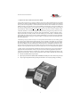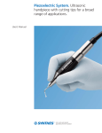
1
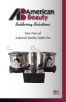
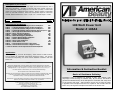
Description of your Product:
100 Watt Infinitely-Variable Power Unit. Input 110-120 VAC 50/60 Hz, with 1
AMP circuit protection. Available in 220-240 VAC when special ordered as
model 105A3 220. Output voltage is 0 to 2.65 VAC (no load). Control Knob
reads 0 to 100% of maximum output voltage. Output wattage is adjustable
from 0 to 100 Watt maximum. Power Unit incorporates Taper Pin connection
method. Product dimensions—3 3/4” x 3 7/8” x 5”. Product weight –2.5 lbs.
MODEL
MAXIMUM
WATTAGE
DESCRIPTION
Recommended Handpieces:
10515 —
10572 —
10573 —
10552 —
10578 —
105133 —
10541 —
105131 —
10517 —
10591 —
105123 —
105142 —
10512 —
10512A —
3/32 Inch Diameter Single Carbon Handpiece*
1/8 Inch Diameter Single Carbon Handpiece*
3/16 Inch Diameter Single Carbon Handpiece *
5/64 Inch Diameter Single Stainless Steel Handpiece*
Ultra-Light Fixed Dual-Electrode Handpiece
Micro-Tweezer Handpiece
Regular Tweezer Handpiece
Micro Wirestripping Handpiece
Regular Wirestripping Handpiece
Small V-Notch Handpiece
Micro Probe Handpiece
Solder Reflow Tool
Lead for Return Current—Std. Clamp
Lead for Return Current—Alligator Clamp
225
250
325
100
225
30
200
30
100
100
50
100
250
100
100 Watt Power Unit
Model # 105A3
* Lead for Return Current required for these handpieces
Applications:
Soldering, Heating, Thermal Wirestripping, Solder Reflow & SMD Removal.
Can be adapted to automated and fixtured production tooling. We strongly
recommend incorporating our Model 10519 Standard Footswitch with this
Power Unit.
WARNINGS
Maximum wattage that is shown reflects a 20-second suggested cycle duration.
Operating handpiece beyond suggested wattage or cycle duration can result in heat
damage to tool. A higher wattage may be used when incorporating a shorter dwell (heating) time
Use with caution to avoid burns, fire or other potential damage
Information & Instruction Booklet
Do not operate near combustible materials
Normal use of this product is likely to expose the user to solders containing lead, which
is known to the State of California to cause cancer and birth defects (or other
reproductive harm) or other proposition 65 listed Chemicals.
General Set-up and Operating Instructions for American Beauty Resistance Soldering
Systems are located inside this booklet or on our website.
All American Beauty Soldering Tools are manufactured by
Assembly Technologies International, Inc.
1177 West Maple Road · Clawson Michigan 48017-1059
(248) 280-2810 · (248) 280-2878
WWW.AMERICANBEAUTYTOOLS.COM
Basics of Resistance Soldering
Resistance heat is obtained by passing a safe, low voltage, high
amperage current through a resistive alloy. By its nature, this heat is
generated instantaneously at the Handpiece's electrodes and stays local
to the precise work area. Active heating occurs only so long as power
is applied to the Handpiece and there is a path for the current from the
Power unit, through the Handpiece and back to the Power Unit.
SETUP & OPERATING INSTRUCTIONS FOR
AMERICAN BEAUTY® RESISTANCE SOLDERING SYSTEMS
SET
SET-UP
First Plug the Power Unit into the plug receptacle of the Footswitch. Next Plug the Footswitch into any properly grounded 120 VAC
V
outlet. With the Power Unit at the lowest setting and turned on, activate the Footswitch. The Power Unit
light will come on, indicating that the unit and Footswitch are working. When the Footswitch is released there is no longer any current being supplied to the Power Unit.
Properly connect the Handpiece to the receptacles or threaded posts that are located on the front or top of the Power Unit. The low range Handpieces are manufactured with custom taper pin terminals for quick connection to the special
receptacles that are employed on the lower output Power Units (push in turning clockwise until snug). The high range and more Heavy
He
Duty Handpieces are manufactured with 3/8” ring terminals for connection to the threaded posts that
are used on the higher output Power Units. The Power Units produce a safe low voltage (AC) alternating current so there’s no concern
con
for polarity.
A Handpieces’ metal electrodes can be notched, milled, slotted, bent or flattened to improve the soldering process. Carbon electrodes
elec
can also be notched, milled or slotted, however the material used in them to create a more intense level
of heat is brittle and cannot be bent or flattened without breaking. Only the core material of the electrodes should touch the work
w
piece while soldering. Remove some of their copper jacket if necessary to insure that it does not come in
contact with the work.
SOLDERING PROCEDURE
The actual process using resistance soldering equipment is simple. A safe (low voltage/high amperage) AC current is passed through
thro
the electrodes and base metals to generate heat. Because of the special high amperage current that is
passed through the resistive part of the electrodes an intense heat is generated where they contact the work. A path for current flow must be established for this process to work. Power Units have either variable or selectable outputs for
handling a wide variety of applications. It is very important to determine the most efficient output to use for each individual application. This is primarily done by trial and error at first, but as you become more accustomed to the equipment
you will be able to predict dwell times and efficient output settings with a far greater level of accuracy and consistency.
In the beginning it may be helpful to use scrap pieces of similar size and material for establishing the most efficient output power to use. Higher outputs may produce dwell times so short that you have little measure of controllability.
Less than one second dwell times are not recommended. Lower outputs can produce long dwell times that will allow time for the heat
he to travel into unwanted areas possibly causing damage to thermally sensitive materials or components
being used.
The goal should be producing the fastest cycle time at which you are comfortably able to create good quality solder joints.
joints
First establish good contact with both of the electrodes and the base metals (close to the intended joint area) then activate the
t
Footswitch. Apply solder to the joint as it heats, then release the Footswitch once the solder is properly flowed.
Because there is no longer any current in the handpiece you can hold the component in place and allow the joint to cool down undisturbed
und
until the solder has finished setting. Evaluate your results and make the necessary adjustments in
order to achieve the most efficient and economical process possible for the application that is currently being performed. When
Whe soldering two pieces of vast size differences you may want to consider pre-tinning the pieces separately and
joining them together by re-flowing the solder, adding just enough new solder to complete the joint.
OPERATING PARAMETERS
The Power Units all have recommended 50% maximum duty-cycles.
cycles. This means that when Power Units are being operated above 50% of their
t
available outputs the dwell (heating) and idle (cooling) time must be regulated in equal
measure. It is important for the idle (or cooling) time to be equal to, or greater than the dwell (or heating) time that is required
requ
for soldering. If it takes 10 seconds for the solder to flow on the application, you must allow a minimum of 10
seconds of cooling time before proceeding to the next solder joint.
To prevent damage to the equipment you must never operate the Power Units for longer than 20 seconds on any settings.
If you have reached the maximum available output of the Power Unit and cannot get the solder to flow in that amount of time there
the may be a problem with the equipment setup or the specific application being attempted may require the
use of a larger Power Unit. Always ensure that the appropriate Power Unit and Handpiece have been selected for the application that
t
you are trying to perform. It is a good idea to go over the basic trouble shooting instructions below for
assistance.
MAXIMUM OPERATING PARAMETERS
The maximum wattage information presented on the other side of this sheet is established in accordance with the maximum allowable
allowab dwell (heating) time being 20 seconds. A higher wattage may only be used when incorporating a
shorter dwell (heating) time. If you have questions regarding any of this information please contact our technical support team at the factory.
OPTIONAL SINGLE ELECTRODE HANDPIECE
Plug your Single Electrode Handpiece into one socket on the Power Unit and the return lead with clip into one of the other sockets.
sock
Attach the clip as close to the intended solder joint as possible. Apply the tip of the electrode directly to the
joint area and depress the Footswitch. Begin feeding solder as soon as enough heat is present for it to flow. Keep the Footswitch
Footswitc depressed until the solder has properly flowed.
BASIC TROUBLE SHOOTING
If you are experiencing any problems:
1.
2.
3.
4.
5.
6.
Check
Check
Check
Check
Check
Check
your power outlet to insure supply voltage is available.
the circuit breaker on the Power Unit, if necessary reset it.
the Handpiece, Power Unit and Electrode connections.
the Electrodes for physical contact with the base metals.
the electrodes for any contamination or oxidation build up.
the work piece for any contamination or oxidation build up.
Follow all safe operating guidelines and ordnances that may apply
.
If you are having any difficulty with the systems setup or operation, please contact us directly for assistance.
Our Technical Support and Customer Service departments are available M-F
M 8:00am to 4:00pm eastern standard time.
Most problems can be solved with a visit to our website, a quick e-mail
e
or a simple phone call to us.
We look forward to hearing from you.
Web: www.americanbeautytools.com
Email: [email protected]
phone: 800 550-2510
fax: 248 280-2878
Assembly Technologies International, Inc. 1177 West Maple Road, Clawson, MI 48017
Information & Instruction Manual for
American Beauty® Resistance Soldering Equipment
Solutions for your difficult soldering needs.
When it comes to soldering equipment, American Beauty® has been
a trusted name in industry for well over one hundred years.
Information & Instruction Manual for
American Beauty® Resistance Soldering Equipment
Manufacturers of American Beauty®
Quality Soldering Tools
Table of Contents
Section
Title
Page
1.0
Introduction
3
2.0
Description
3
2.1
The Science of Electricity
4
3.0
Safety—General
5
3.1
Safety—Heat Related
5
3.2
Safety—Ventilation Related
5
3.3
Safety— Electrical Current
5
4.0
Resistance Soldering Equipment Uses
6
5.0
Basic System Configuration
6
5.1
Choosing the Correct Handpiece
6
5.2
Handpiece Recommendations
7
5.3
Choosing the Correct Power Unit
8
5.4
Power Unit Recommendations
8
6.0
System Set-up Instructions
9
7.0
Developing Your Soldering Process
9
7.1
Determining Appropriate Power Levels
10
7.2
Maximum Operating Parameters
10
8.0
Troubleshooting Your Equipment
11
2
Information & Instruction Manual for
Manufacturers of American Beauty®
Quality Soldering Tools
1.0 Introduction
If you have only recently become aware of Resistance Soldering Equipment and its various uses you may
find it interesting to note that this is actually not a new concept. The American Beauty® line of Resistance
Soldering and Thermal Wirestripping equipment has been manufactured and available for over fifty years.
The entire line of American Beauty® soldering equipment is developed and manufactured exclusively by
Assembly Technologies International Inc.™ located here in suburban Detroit, Michigan.
As the manufacturer of the largest assortment of power units, handpieces and related accessories available
anywhere, we pride ourselves in being the worlds leader in the design and development of resistance based
soldering equipment. Each item that we manufacture is being continuously evaluated and improved upon so
that we may offer you the highest performance along with the safest, most efficient, user friendly equipment
available for any Resistance Soldering or Thermal Wirestripping applications that you may be considering.
All American Beauty® products are manufactured using the highest quality of materials that are available
and are assembled with great care so they will consistently conform to our exacting quality specifications.
This is why we are able to offer our Industry Best “Three Year Warranty Policy” which may be viewed
any time on our Web-Site at www.americanbeautytools.com under the Support heading.
We are certain that with proper care and maintenance, all of the American Beauty® Resistance Soldering
and Thermal Wirestripping equipment you have purchased will provide a long and reliable service life.
This manual has been developed to address many of the specific questions and concerns you may have that
relate to the Principles of Resistance Soldering, Thermal Wirestripping and other applications where the use
of an intense localized heat may be beneficial. We will cover general operating procedures, instructions and
helpful guidelines as well as some very basic safety issues and concerns that may be associated with the use
of this type of equipment. You will also find helpful information within the Support area of our Web-Site.
We are confidant that you will find the information that is being presented within this manual to be helpful
and informative, however if you have questions that are beyond the scope of what this manual covers please
take a moment to call us toll free at (800) 550-2510.
You will find that we are always happy to help provide “Solutions for Your Difficult Soldering Needs”.
2.0 Description
All soldering applications require the introduction of enough heat to activate the flux and flow the solder.
Whenever tools that are being used to perform a soldering application take too long to achieve the required
process temperature, the potential for thermal damage exists. Resistance Soldering Equipment gives a user
the ability to manufacture an intense level of heat that can be regulated and localized within the intended
solder joint in a more efficient manner than most other available methods. This means a faster soldering
process and less time for dissipative heat to cause any thermal damage to the components that are being
soldered or any materials or components that may be within the immediate area surrounding the intended
solder joint.
Resistance Soldering is accomplished by producing a safe (low-voltage/high-amperage) AC current which
is then passed through special electrodes (manufactured out of high resistance metal alloys or other resistive
materials) to generate an intense level of available heat. A closed loop circuit is required so that the current
can be passed from one resistive electrode directly through the base metals that are being soldered and into
the other electrode back to the power unit. An isolated transformer is used so that the current does not stray
or leak into unwanted areas, but takes the most direct path from one electrode to the other which completes
the circuit that is required to generate the desired heat. The resistance of the special electrodes that are used
creates the majority of the heat that is being generated. Any additional resistance that exists at the point of
contact and within the base metals that are being soldered will increase the amount of available heat that can
be generated within the solder joint. By regulating the output voltage of the resistance soldering power unit
the heat that is generated can be adjusted to the specific level required for the soldering application that is
being performed.
3
Information & Instruction Manual for
American Beauty® Resistance Soldering Equipment
Manufacturers of American Beauty®
Quality Soldering Tools
2.1 The Science of Electricity
Resistance heat can be developed because of the three fundamental forces that control all electrical circuits;
voltage, amperage, and resistance.
Voltage
Its scientific name is electromotive force which is usually represented in formulas with a capital letter “E”.
The electromotive force or electrical pressure that moves an electrical current through a conductive material
is measured in units that are called volts. One volt is equal to the amount of electromotive force necessary to
force one ampere of current to flow through a resistance of one ohm. Generally a higher voltage means that
more current will flow and a lower voltage means that less current will flow through an electrical circuit.
A voltmeter can be used to measure the amount of voltage (electrical pressure) in the circuit
Amperage
The scientific reference is intensity of current flow usually represented in formulas with a capital letter “I”.
The rate at which an electrical current will flow through a conductive material can be measured in units that
are called amperes. One ampere equals a flow of 6.25 x 10²³ electrons (called one coulomb) per second.
Using the water flowing through a pipe analogy to describe the way that current flows along a conductor,
current will flow more readily through a short thick conductor than through a long narrow conductor.
An ammeter can be used to measure the amount of current that is flowing through a circuit
Although a greater amount of voltage can increase the amount of current that will flow along a conductor,
the actual amount of current that flows will also be dependant upon the amount of resistance encountered.
Resistance
Resistance is the property of a material which resists or opposes the flow of an electrical current through it.
The actual resistance (R) of a material is dependant upon its resistivity (ρ) which can be different for each
material, along with its physical characteristics (such as the materials overall length and cross-sectional
area).
This can generally be shown as R = ρL/A, where R is the resistance in Ω (ohms), ρ is the known resistivity
of the conductive material, L is the length of the conductor and A the cross sectional area of the conductor.
Resistivity (ρ): is unique to each material being soldered.
Length (L): A greater length increases the amount of resistance and a shorter length decreases resistance.
Area (A): A greater area decreases the amount of resistance and a smaller area increases the resistance.
An ohmmeter can be used to measure the amount of resistance that exists in a conductive material
Resistance Heat
Resistance heat is the heat that is developed as an electrical current is passed through a conductive material
because of that conductive material’s resistance (or opposition) to the current that is being passed through it.
Whenever an electrical current (I) flows through a conductive material with resistance (R), electrical energy
is converted to heat at a rate of power (P) that may be calculated as P = I² R, where P is the power measured
in watts, I is the current measured in amperes and R is the resistance measured in Ω (ohms).
The heating effect of resistance is often considered undesirable in the transmission of current for most
electrical applications and must be minimized, but it is very useful for intentionally generating electrical
heat for a variety of uses, in this case Resistance Soldering. Understanding that some materials have a
higher level of resistivity than others and that the actual amount of resistance can be altered by changing the
physical characteristics of the material is an important part of us creating and utilizing resistance heat for
various soldering applications.
4
Information & Instruction Manual for
Manufacturers of American Beauty®
Quality Soldering Tools
3.0 Safety—General
All of the American Beauty® resistance soldering or thermal wirestripping equipment that is manufactured
by Assembly Technologies International Inc.™ should be operated in complete compliance with all federal,
state and local regulations that exist pertaining to the various uses for this type of equipment. This includes
actual use, storage, safe handling and disposition of any materials, components, tools or other products that
may be used in conjunction with this equipment. Consult the manufacturers of the solders, fluxes, cleaning
agents and other products that might be used along with this equipment and request a copy of their current
Material Safety Data Sheets (MSDSs) or other available information, documentation or specific warnings
regarding each of their individual products. It is important to become familiar with all MSDSs, operations
manuals, information and instruction sheets, stickers, labels, inserts and other related material or documents
that are currently (or that become) available regarding our products and any other materials or equipment
that may be used in conjunction with them.
3.1 Safety—Heat Related
As previously stated, all soldering applications will require the introduction of some level of heat to be
able to activate the flux and melt and flow the solder. It is important to exercise caution when operating any
products or equipment that are used to manufacture or generate the required heat. The development of safe
operating practices and proper training procedures will help eliminate the possibility of any accidental burns
or other potential hazards. All operating personnel must be aware of the proper handling procedures for any
combustible or flammable materials that might be required for your specific soldering applications.
Systems should be turned off whenever they are not in use or they are going to be left temporarily
unattended in order to help prevent any accidental actuations.
3.2 Safety—Ventilation Related
Proper ventilation is a significant consideration for any type of manufacturing and processing environment.
This fact is especially true where there is a potential for smoke, fumes, vapors or other irritants and airborne
contaminants that exist or develop. There are a wide variety of sizes, styles and types of ventilation, exhaust
and air filtering systems available which have been specifically designed for the removal of offensive odors
and potentially harmful smoke, fumes or vapors that may be given off during various soldering applications.
Be sure that you have obtained, read and fully understand all of the available documentation regarding the
proper use, storage and safe handling of any materials and equipment that you may be intending to use with
your soldering applications. This should include any requirements for protective clothing shielding or other
apparatus that may be specified.
3.3 Safety—Electrical Current
Resistance Soldering equipment consists of various electrical devices that are intended for use in soldering
applications to help improve the safety, quality and efficiency of many of your current soldering processes.
This equipment must be used in complete compliance with all of the applicable safe operating procedures,
local ordinances and other guidelines and regulations that exist for the locations where they are being used.
Failure to follow the specific instructions, procedures and guidelines can result in the possibility of injuries
to your operating personnel or damage to equipment which could otherwise have been avoided.
The output that is produced by all of the American Beauty Resistance Soldering Power Units is a very safe
low-voltage AC current this equipment operates on standard 110-120 or 220-240 AC line voltage. However,
opening the Power Unit enclosure can expose an operator or individual to the possibility of various
electrical hazards. Any troubleshooting practices and maintenance procedures that may be required should
be attempted by qualified personnel only.
5
Information & Instruction Manual for
American Beauty® Resistance Soldering Equipment
Manufacturers of American Beauty®
Quality Soldering Tools
4.0 Resistance Soldering Equipment Uses
Because of the ability to very rapidly produce an intense level of controlled, localized heat, directly where
it is needed for soldering, you will find that almost any soldering method or process that currently exists can
be improved upon with the use of resistance soldering equipment. The wide variety of available handpieces
manufactured for use with various power units ranging in maximum outputs of 100 to 3000 watts give you
the ability to perform a virtually infinite number of soldering applications that can range from very small
electronic components all the way up to 3” diameter thin wall metal pipes or other tubing that is used in a
variety of plumbing, refrigeration and HVAC applications.
With the correctly configured systems you will always be able to produce the higher temperatures that are
required for various hard solders and even many of the low to mid-temperature brazing materials that exist.
Resistance soldering equipment is often the perfect choice for applications involving temperature sensitive
components that are either being soldered themselves or are located within close proximity to the materials
that are being soldered. For this type of soldering applications it is very important to be able to apply a high
enough temperature to the correct location and for the shortest amount of time possible in order to minimize
the amount of heat that travels away from the solder joint. This is one of the primary reasons for choosing
resistance soldering equipment over so many of the other types of soldering tools and equipment that exist.
Some of the other reasons for resistance soldering are more consistent repeatability and improved quality,
throughput and efficiency. As your operators gain more experience the number of uses is sure to increase.
Thermal Wirestripping is another type of application that resistance soldering equipment may be used for.
This is best accomplished by using one of the many specially designed handpieces that have been developed
specifically for thermal wirestripping applications along with the correct resistance soldering power unit.
Using the correct equipment for any process greatly affects the quality and efficiency level you achieve.
5.0 Basic System Configuration
When configuring the basic resistance soldering system that will be required for any application,
your three primary components will be a handpiece, a power unit and a footswitch. There are a wide
variety of American Beauty® resistance soldering handpieces and several power units available to choose
from along with various accessories which might also be recommended or required for more specialized
applications. It is important to properly match the handpiece and power unit to the intended soldering
applications when configuring a system, in order to be able to maximize the full range of benefits that can
be obtained with the use of resistance soldering equipment. You should determine the most appropriate
handpiece to use for the application first and then you will be better able to decide on the power unit that
will give you the widest possible working range and versatility. If you are considering using resistance
soldering equipment for more than one application, you may find it beneficial to evaluate the requirements
of the largest application first. This approach can decrease your total cost of ownership by purchasing a
single power unit to work in conjunction with multiple handpieces.
5.1 Choosing the Correct Handpiece
When you are deciding on the most appropriate handpiece to use for an application you should consider the
process that is being developed along with the size, shape and type of the materials that are being soldered.
The handpiece style that is being chosen for a specific application should allow for proper placement of the
electrodes to the work based on the accessibility to the solder joint area along with any special horizontal or
vertical orientation of the handpiece that may be required to comfortably perform the soldering task. The
electrodes size requirement will help determine the required handpiece size. The electrodes size should be
properly matched to the work requirements, because a greater area of contact between the electrode and
work surfaces will help to increase the overall efficiency of the thermal transfer that will be taking place.
Even though electrodes can be modified in order to maximize their efficiency, you should choose the type
and size that will most appropriately match the intended application prior to these modifications being
made.
6
Information & Instruction Manual for
Manufacturers of American Beauty®
Quality Soldering Tools
5.2 Handpiece Recommendations
The handpiece styles that are currently available include single electrode (used with a lead for current
return) dual electrode stationary, dual electrode tweezers, dual electrode pliers, dual electrode forks and a
variety of handpieces designed especially for thermal wire stripping. All of the handpiece styles that are
listed here are available in a variety of sizes in order to best meet the specific application requirements that
might exist.
Single Electrode Handpieces give you the ability to direct the heat to a specific point of contact in the
same manner as you would with a conventional soldering iron but with a much higher thermal capacity
available. Using a lead for current return will be necessary with the use of this style of handpiece in order
to complete the required current path. The most appropriate handpiece size to choose is directly related to
the electrode that will work best for the application that is being considered. Choose the electrode size in the
same manner as you would when choosing a soldering iron tip size. Match the electrode diameter to the
area being soldered.
Stationary Dual Electrode Handpieces were initially developed for the highly repetitive soldering of
similar sized terminations (terminal strips, multiple termination buss bars, etc.). They may be used on
applications similar to those where single electrode handpieces might be considered but they do not require
the use of a lead for current return to operate properly. The electrode tips are positioned in a close proximity
to one another and will complete the current path by passing current through the surface of the material that
is to be heated. With minor adjustments or modifications to the electrodes (bending, grinding, etc.) they can
be positioned in a manner appropriate to the requirements of the application that they are intended for.
Tweezer Style Dual Electrode Handpieces will allow you to direct the heat to a specific area while
actually holding the component in place during a soldering application. After flowing the solder you can
deactivate the footswitch while continuing to hold the component in place to cool. This helps to eliminate
cold solder joints that might be caused by agitation of the joint while it is cooling. The metal electrodes
being used in these handpieces can be bent to improve the ergonomic feel of the handpiece and the
electrode tips can be contoured to custom fit the work surface improving the thermal transfer from the
electrodes into the work.
Pliers Style Dual Electrode Handpieces are similar in design to tweezer style handpieces but were
developed for heavier applications and can obtain much higher operating temperatures. These handpieces
incorporate carbon block electrodes that allow you to operate at temperature levels which could actually
melt the metal alloy electrodes that are used in the tweezer style handpieces. Carbon block electrodes have
increased work surfaces and can be contoured to increase the surface contact area of the electrodes to the
work even further. This increased contact area will greatly improve the thermal transfer that takes place
during soldering.
Fork Style Dual Electrode Handpieces are similar in design to the largest heavy-duty pliers-style
handpieces. These handpieces incorporate an entirely different type of adapter and electrode configuration
allowing for an increased level of versatility. Because the electrodes are rods and the adapters can be
swiveled for more specific orientation of the electrode tips to the required surface area of the work many
applications may be performed with an increased level of efficiency and control.
Thermal Wirestripping Handpieces have been developed primarily for the purpose of thermally stripping
the insulation from wires to help minimize the hazard of nicking scoring or otherwise damaging the
conductors. These handpieces have closed loop elements which will begin to heat as soon as the power unit
is activated. The output of the power unit should be adjusted only high enough to allow the elements of the
handpiece to reach the temperature required for melting through the insulation without burning it. The two
basic types of thermal wirestripping handpieces that are currently manufactured are the tweezer style and
the V-notch style. The tweezer style handpieces are designed for stripping smaller gauge wires and the Vnotch style are designed for stripping the larger gauge wires.
Solder Reflow Tools are similar in design to the V-notch style wirestripping handpieces and although they
may be used for wirestripping they were developed for a wide variety of other applications which include
solder reflow, wax sculpting, wood burning, trimming plastics, stained glass work and much more.
7
Information & Instruction Manual for
American Beauty® Resistance Soldering Equipment
Manufacturers of American Beauty®
Quality Soldering Tools
5.3 Choosing the Correct Power Unit
When deciding on the correct power unit to be used for an application the final decision should be based not
only on the handpiece that has been chosen for that application but also the temperature that is required for
the solder that will be used. This is especially true for hard solders and various brazing materials which
require significantly greater levels of heat in order to flow and wet properly. You should always consider a
power unit that has a higher available output than what you have determined to be required for the
application being evaluated. This will give you assurance that the power unit will not require continuous
operation at its maximum output level. This will also insure that you have the ability to increase the output
power level and lower the required cycle times as the operators become more proficient with a soldering
process. Another reason for the higher output consideration is planning ahead and allowing for potential
growth into larger applications as the need may arise.
5.4 Power Unit Recommendations
The variety of power unit types that are currently available include infinitely variable, selectively variable
and multiple output models. You will find that each specific type of power unit listed here is manufactured
in a variety of maximum available output levels. All of the recommendations shown below are based upon
broad speculation and should only be used as a basic guide to determine the most appropriate equipment for
your potential requirements.
Infinitely Variable Power Units incorporate a solid state voltage regulating device in order to allow the
finest level of adjustment to their output power.
This type of power unit is available in either 100 watt or 250 watt maximum available outputs.
•
105A3 power units are capable of producing up to 100 watts of power and may be used to solder
materials and components that do not exceed 1/8” diameter.
•
105A12 power units are capable of producing up to 250 watts of power and may be used to solder
materials and components that do not exceed 1/4” diameter.
Selectively Variable Power Units incorporate an eight (8) position tap switch along with an off center
tapped transformer secondary. Giving the power unit eight different output selections at each of the high,
medium and low levels of output power or 24 specific output selections to choose from.
This type of power unit is available in either 1100 watt or 1800 watt maximum available outputs.
105B2 power units are capable of producing up to 1100 watts of power and may be used to solder materials
and components that do not exceed 1/2” diameter.
105C1 power units are capable of producing up to 1800 watts of power and may be used to solder materials
and components that do not exceed a 1” diameter.
Multiple Output Power Units incorporate an off center tapped transformer secondary to allow for either
high, medium and low levels of output power.
This type of power unit is available in either 1800 watt or 3000 watt maximum available outputs.
105C2 power units are capable of producing up to 1800 watts of power and may be used to solder materials
and components that do not exceed the 3” diameter thin wall tubing recommendations.
105D1 power units are capable of producing up to 3000 watts of power and may be used to solder materials
and components that do not exceed the 3” diameter thin wall tubing recommendations.
8
Information & Instruction Manual for
Manufacturers of American Beauty®
Quality Soldering Tools
6.0 System Set-up Instructions
The first thing to do is fit the three prong 5-15 NEMA plug that is attached to the power unit cord into the
receptacle portion of the piggy-back style plug that is attached to the footswitch cord assembly and then fit
the plug portion of the footswitch into any properly grounded 120 VAC outlet. With the power unit at the
lowest setting and turned on, activate the footswitch. The light on the power unit should come on, indicating
that the power unit and footswitch are both functioning. When the footswitch is released the light should go
out as there is no longer any current being supplied to the power unit. Attach the handpiece connections to
the appropriate taper pin receptacles or threaded posts that are located on the front or top of the power unit.
Single electrode style handpieces will require the use of an appropriate lead for current return to provide the
required closed circuit in order to achieve proper current flow and generate heat.
The power units produce a safe low voltage, alternating (AC) current so there is no concern for polarity.
Heavy-Duty handpieces that have been developed for the higher power ranges are manufactured with 3/8”
ring terminals for a more permanent and mechanical connection to the threaded posts that are employed on
the higher output power units. This minimizes the electrical resistance that may exist at this connection and
helps eliminate the possibility of the handpiece connection loosening over time. Handpieces that have been
developed for the lower power ranges are manufactured with specially designed taper pin terminations for
quick connection to the custom receptacles that are employed on the lower output power units. This gives
users the ability to quickly change back and forth between the variety of handpieces that may be required
for a specific process. For connection you simply push the taper pin into the receptacle turning clockwise
until it is snug.
Converting your Taper Pin connectors to Ring Terminals:
When a process is developed involving the lower output power units, which does not require changing
handpieces the mechanical connection as mentioned above can be implemented. This is done by removing
the taper pins from the handpiece and attaching 1/4” ring terminals in their place. The handpiece can then
be attached to the power unit with the use of 3/4” length 1/4-20 brass bolts, because the receptacles are
already tapped to accept the 1/4-20 bolts.
7.0 Developing Your Soldering Process
With the equipment properly setup as described above it is time to develop your resistance soldering
process. Developing the soldering process using resistance soldering equipment is quite simple and will be
very easy to master, once you fully understand the basic principles of electricity that are involved in the
development of resistance heat. This manual should answer the majority of your questions and get you on
the right track.
All of the American Beauty® resistance soldering power units have a specially developed transformer that
converts your standard 110-120 VAC input line voltage into a completely safe (low voltage/high amperage)
AC electrical current. When this safe, low voltage current gets passed through a resistive material an intense
amount of heat can be developed within the immediate area of resistance. This immediate area of resistance
exists within the intended solder joint area of the base materials located between the tips of the electrodes.
Resistive heat will be developed because of the resistance that an electrical current encounters when being
passed through the electrodes and the base metals. A closed circuit is required in order to maintain the path
for proper current flow. The amount of heat produced is determined by the output current being supplied by
the power unit. It is important to determine the output current that is required to produce the correct level of
heat for the process that is being developed. Your primary goal should be to establish the shortest dwell
time in which you can comfortably create good quality solder joints. In the beginning this must be
accomplished by trial and error, however as you become more accustomed to the resistance soldering
equipment you will become better able to predict the required dwell times and the most efficient output
settings with a far greater level of accuracy and consistency.
9
Information & Instruction Manual for
American Beauty® Resistance Soldering Equipment
Manufacturers of American Beauty®
Quality Soldering Tools
In the beginning stages of your new process development it is often very beneficial for you to use dummy
components or scrap pieces of similar size and material to the actual components that you will be soldering.
This should help you to establish the most efficient power unit output to be used without causing unwanted
damage to any expensive materials or components during the initial process development stages.
Whenever a soldering application involves joining together pieces of vastly different sizes, or components
that may be highly sensitive to thermal damage, you may want to consider pre-tinning the pieces separately
and then joining them together by re-flowing the solder and adding enough new solder to complete the joint.
7.1 Determining Appropriate Power Levels
Establish a good contact with the base materials (close to the intended solder joint area) and both electrodes
(or the single electrode and return harness clip) and activate the footswitch. Apply solder to the joint area as
it is heating, then release the footswitch once the solder has properly flowed. Because there is no longer any
current being supplied to the handpiece, you will be able to hold the components in place while allowing the
solder joint to cool undisturbed until the solder has finished setting.
Upon completion of the first solder joint you should be able to evaluate the results that have been achieved.
Based upon this evaluation you should be able to determine whether there are any adjustments that might be
recommended or even required to improve the soldering process. You should be especially concerned about
the amount of dwell time that is required in order to properly flow the solder. Remember that your goal is
to establish the shortest dwell time in which you can comfortably and efficiently create a quality
solder joint.
If the output of the power unit is set too high you can produce dwell times so short that you will have little
or no measure of controllability. Dwell times that take less than one second are generally not recommended
without the use of a precision timer unit. If the dwell time is too short and a precision timer unit is not going
to be used you should adjust the output of the power unit to a lower level (this will increase the dwell time
and improve the level of process controllability) and then attempt the soldering process again.
If the output of the power unit is set too low you can produce dwell times that are too long which increases
the time available for heat to travel away from the solder joint and into unwanted areas. Longer dwell times
increases the chances of causing damage to thermally sensitive components or materials that are being used.
If the dwell time is longer than necessary you should increase the output of the power unit to a higher level
(this decreases dwell time and the possibility of thermal damage) and attempt the soldering process again.
7.2 Maximum Operating Parameters
All of the resistance soldering power units have a recommended 50% duty-cycle. What this means is that if
a power unit is being operated at levels above 50% of their total available output power the dwell (heating)
and idle (cooling) time must be regulated in equal measure. It is important for the idle (cooling) time to be
equal to, or greater than the dwell (heating) time that is required for soldering. If it takes 10 seconds for the
solder to flow properly you must allow a minimum of 10 seconds of cooling time before proceeding to the
next solder joint. You should also monitor the handpiece cables for excessive heat buildup during soldering.
If you find excessive heat building up in the cables you should further lengthen the required cooling time.
To prevent damage to the equipment you must never operate power units for longer than 20 seconds on any
setting while soldering. If you have reached the maximum available output of the power unit and cannot get
the solder to flow within this amount of time you should make sure there is no problem with the equipment
set-up and then verify good electrical contact between the electrodes and the base materials or components.
Once you have verified the equipment set-up and the electrical contact the next area for consideration is the
power unit and handpiece configuration you have chosen for the application being attempted. The specific
application that you are trying to perform may require a higher output power unit and a different handpiece
to achieve the desired results. Although this segment does not apply to thermal wirestripping applications,
the handpiece cables should still be monitored for excessive thermal buildup.
10
Information & Instruction Manual for
Manufacturers of American Beauty®
Quality Soldering Tools
7.3 Improve Your Process With a Precision Timer Module
After you have properly set up a resistance soldering system and you have determined the correct operating
parameters to be used you should immediately begin to notice the improvements in quality and consistency.
Once you have had an opportunity to evaluate all of the benefits that are achieved with the use of resistance
soldering systems you may decide to improve the repeatability and consistency of your process further still.
The next level of improvement to your soldering process is easily accomplished by simply incorporating an
American Beauty® Model 105PTM (Precision Timer Module) into the present resistance soldering system.
The Model 105PTM is a self contained, digital LCD, multi-function, precision timing control device, that
has been specifically developed for use with many of the American Beauty® resistance soldering systems
and power units that are currently available. This timer module gives you the ability to establish consistent
and repeatable dwell times that are accurate to within a hundredth of a second. This improved repeatability
helps eliminate the need for relying on an operators ability to consistently respond to the soldering process
that is being performed.
The following set-up steps show how easy it is to incorporate the timer module into your soldering system.
The precision timer module should be plugged directly into any standard 5-15R NEMA 110-120vac outlet.
The footswitch plugs into the low voltage 3.5mm female jack on the lower front panel of the timer module.
The American Beauty® resistance soldering power units plug into the 5-15R NEMA receptacle that is also
located on the lower front panel of the timer module. The 10519 Footswitch with the piggy-back style plug
receptacle is not required because the precision timer module has its own low voltage footswitch supplied.
Carefully read all of the documentation included with the timer module in order to properly determine the
appropriate function that should be used for your specific resistance soldering application requirements.
Each of the various functions that are available can be chosen by adjusting the output mode selector to the
appropriate letter designator. The time range mode and time value are used to determine the interval setting.
•
•
•
This Item is available in 220 VAC upon request.
High Capacity Precision Timer Module (Model 105HCPTM) is available for use with C and D series power units.
Always verify the output mode and the processing time selections are correct before operating your soldering
11
Information & Instruction Manual for
American Beauty® Resistance Soldering Equipment
Manufacturers of American Beauty®
Quality Soldering Tools
8.0 Troubleshooting Your Equipment
Only authorized persons that have received training in the proper servicing of electrical equipment should
attempt to diagnose or make repairs to any of your American Beauty® resistance soldering equipment.
You will find that the most important tool to have available when troubleshooting your resistance soldering
equipment will be a standard AC volt-meter or a multi-meter that has a setting for reading the AC voltage.
®
Never attempt to service your American Beauty resistance soldering equipment while it is still plugged in.
These are the troubleshooting steps to follow assuming that you have properly set up your soldering system
and have already been able to properly perform the soldering process before any problems have developed.
If the proper AC voltage cannot be verified at each of the steps listed below, continue on with the next step.
1. Verify that the proper AC voltage is being conducted into the handpiece’s electrodes.
If proper AC voltage is available at the electrodes but no heat is being developed they may require cleaning
where they make contact with the base metals. Contamination, dirt and burnt flux may encumber the current
flow that is required from the contact surfaces of the electrodes and through the base metals.
2. Verify that the proper AC voltage is being conducted to the electrode adapters.
If proper AC voltage is available within the electrode adapters but unavailable from the electrodes be sure
that their contact surfaces have not become contaminated and that the electrodes have not become loosened.
Make sure that any set-screws that belong in the adapters are still in place and are properly tightened.
3. Verify that the proper AC voltage is being conducted from the power unit’s output receptacles.
If proper AC voltage is available at the power unit output but is unavailable at the electrodes and adapters
be sure the handpiece is securely connected to the power unit and check the electrodes and adapters again.
If proper AC voltage is still unavailable at the electrodes or the adapters the handpiece may have developed
a short in the cables, or one of the wire connections may have become loose. If you are unable to determine
the source of the problem you may wish to return your handpiece to the factory for an evaluation and repair.
4. Verify that the proper 120 VAC line voltage is available from the receptacle of the footswitch’s piggyback plug assembly when the footswitch is being depressed.
If proper line voltage is available from the receptacle of the footswitch’s piggy-back plug assembly but the
proper output is unavailable from the power unit, be sure that the power unit is turned on and that the circuit
breaker has not been tripped. If the circuit breaker has not been tripped the problem may exist inside of the
power unit and you may wish to return it to the factory for an evaluation and repair.
5. Verify that the proper 120 VAC line voltage is available from the main power supply receptacle that the
footswitch’s piggy-back plug assembly was plugged into.
If proper 120 VAC line voltage is available from the main power receptacle but it is unavailable from the
receptacle of the footswitch’s piggy-back plug assembly you may wish to return your footswitch assembly
to the factory for an evaluation and repair.
You may find it easier to troubleshoot your resistance soldering system by following the verification steps
that are listed above in the reverse order (similar to the initial set-up procedures) tracing voltage from the
source until you reach the point where it becomes unavailable and then determining the exact cause.
You will find more Troubleshooting information available within the Support section of our Web-Site.
All American Beauty Resistance Soldering Systems are proudly manufactured in the U.S.A., by
Assembly Technologies International, Inc. We are located at 1177 W. Maple Road, Clawson MI
48017. We can be found on the internet @ WWW.AMERICANBEAUTYTOOLS.COM or via telephone,
toll free at 800.550.2510.
Thank you for your business!
12