1
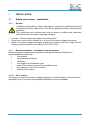
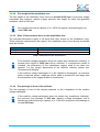
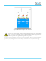
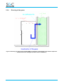
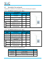
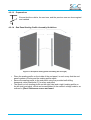
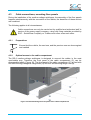
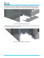
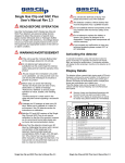
DR-6C
MEDIUM VOLTAGE SWITCHGEAR
COMPACT RING MAIN UNIT
DW646314
Installation Manual: DR-6C / DR-6+ C
THE SPECIALIST IN MEDIUM VOLTAGE SWITCHGEAR
SGC - SwitchGear Company nv. - Moorstraat 24 - B-9850 Nevele - Belgium
Tel : +32 (0)9/321.91.12 - Fax +32 (0)9/321.91.13 - e-mail: [email protected] - www.switchgearcompany.eu
© 2013 SGC – SwitchGear Company nv
All rights reserved.
The information provided herein may not be reproduced and/or (re)published in any way and by any means (electronic or
mechanical), without the prior, explicit written authorization of SGC - SwitchGear Company nv.
The information provided herein is based on general data concerning the construction, known at the time of publication,
and concerning the qualities of the material and working methods. Consequently, the right to make changes is reserved.
The information contained within is applicable to the standard version of the DR-6 medium-voltage switchgear.
Therefore, SGC - SwitchGear Company nv cannot be held liable for any damage resulting from specifications that differ
from the standard version of the DR-6 medium-voltage switchgear.
The available information has been assembled with the greatest possible care, but SGC - SwitchGear Company nv
cannot be held liable for any mistakes in the information, or the consequences thereof.
The user names, trade names, trademarks, etc., used by SGC - SwitchGear Company nv cannot, in accordance with the
legislation concerning the protection of trademarks, considered to be free.
ii
Installation Manual – DR-6C/ DR-6+ C
DW646314
CONTENTS
CONTENTS .................................................................................................... iii PREFACE ....................................................................................................... v About this manual ....................................................................................................................... v Pictograms and safety symbols in and on the medium voltage switchgear ............................... v Pictograms in the documentation .............................................................................................. vi Related documentation .............................................................................................................. vi Service and technical support .................................................................................................. vii General safety directions and instructions ................................................................................ vii Intended use ............................................................................................................................. viii 1 INSTALLATION ...................................................................................... 1-1 1.1 1.1.1 1.1.2 1.1.2.1 1.1.2.2 1.1.2.3 1.1.2.4 1.1.2.5 1.1.2.6 1.1.2.7 Safety guidelines instructions – installation ........................................................... 1-1 General .................................................................................................................. 1-1 Recommendations – installation room parameters ............................................... 1-1 Floor surface .......................................................................................................... 1-1 Environmental conditions ...................................................................................... 1-2 Ventilation .............................................................................................................. 1-2 Free height of the installation area ........................................................................ 1-3 Sizes of the entrance doors to the installation area ............................................... 1-3 Free passage in front of the cubicles ..................................................................... 1-3 Internal arc protection ............................................................................................ 1-4 2 DR-6C INSTALLATION GUIDELINES ................................................... 2-1 2.1 2.1.1 2.1.2 2.1.3 2.2 2.2.1 2.2.2 2.2.3 2.2.4 2.3 2.3.1 2.3.2 2.3.3 2.3.4 Installation in the presence of a cable duct ........................................................... 2-1 General .................................................................................................................. 2-1 Required conditions ............................................................................................... 2-1 Diverting of the gases ............................................................................................ 2-2 Installation in the presence of an expansion room behind the switchgear ............ 2-3 General .................................................................................................................. 2-3 Required conditions ............................................................................................... 2-3 Required Materials ................................................................................................ 2-3 Diverting of the gases ............................................................................................ 2-4 Installation in the absence of a cable duct or transformer room ............................ 2-5 General .................................................................................................................. 2-5 Required conditions ............................................................................................... 2-5 Required materials ................................................................................................ 2-5 Gas escape route .................................................................................................. 2-6 3 DR-6+ C INSTALLATION GUIDELINES ................................................ 3-1 3.1 3.2 3.2.1 3.2.2 General .................................................................................................................. 3-1 Required conditions ............................................................................................... 3-1 Required Material .................................................................................................. 3-1 Diverting of the gases ............................................................................................ 3-2 4 Switchgear arrangement ...................................................................... 4-3 4.1 4.1.1 4.1.2 4.1.3 DW646314
Anchoring the DR-6C medium-voltage cubicle ...................................................... 4-3 Installing the fixation clips ...................................................................................... 4-3 Installing the fixation clips with use of a soccle ..................................................... 4-3 After installing the fixation clips, the DR-6C medium-voltage cubicle can be
positioned in its definitive place. The rear side of the DR-6C medium-voltage
cubicle is now fixed into place.Anchoring front side of DR-6C medium-voltage
switchgear ............................................................................................................. 4-3 Installation Manual – DR-6C/ DR-6+ C
iii
4.1.3 4.2 4.2.1.1 4.2.1.2 4.2.1.3 4.2.1.4 4.2.1.5 4.3 4.3.1 4.3.2 4.3.3 4.3.4 4.4 4.5 Anchoring front side of DR-6C medium-voltage switchgear .................................. 4-4 Assembly of the end panels .................................................................................. 4-6 Kit DR000010 (End Panel Left - Right) .................................................................. 4-6 Kit DR002010 (End Panel Left - Right) .................................................................. 4-6 Preparations .......................................................................................................... 4-7 End Panel Sealing Profile Assembly Guidelines ................................................... 4-7 Assembly Guidelines End Panel ........................................................................... 4-8 Cable connections, mounting floor panels ............................................................. 4-9 Preparations .......................................................................................................... 4-9 Optimal access to the cable compartment ............................................................ 4-9 Assembly guidelines for cable connection ........................................................... 4-11 Possible bushings ................................................................................................ 4-13 Refitting the door ................................................................................................. 4-15 Measuring phases sequence ............................................................................... 4-16 5 INITIAL COMMISSIONING..................................................................... 5-1 iv
Installation Manual – DR-6C/ DR-6+ C
DW646314
PREFACE
About this manual
This document is intended as a reference for qualified and trained operators to install the
medium voltage switchgear in a safe and economical way.
This document uses the term “medium voltage switchgear” to denote a random, but in
actual practice, existing combination of DR6 functions that, mutually coupled and
connected, constitute a client-specific transformation or distribution station. See: “General
description”.
The chapters and sections are numbered. The page numbers (consisting of the chapter
number and the page number) and the document code can be found at the bottom of
every page.
In the documentation the words “left”, “right”, “front” and “behind” are used to indicate a
specific part of the medium voltage switchgear. The starting point is always the position of
the operator, standing in front of the medium voltage switchgear, facing the switchgear.
Pictograms and safety symbols in and on the medium voltage
switchgear
Depending on the version, the following pictograms are used on the medium voltage
switchgear:
WARNING
Danger of high voltage
Access to this cubicle is only allowed after this cubicle and both the directly
adjacent cubicles (previous and next one) are de-energized.
WARNING
Drilling prohibited.
Drilling is strictly prohibited on surfaces equipped with this pictogram.
DW646314
Installation Manual – DR-6C/ DR-6+ C
v
Pictograms in the documentation
The following pictograms apply to the medium voltage switchgear user documents:
CAUTION!
A procedure that can, if not carried out with the proper care, result in damage to
the medium voltage switchgear, the surrounding area or the environment.
WARNING
High Voltage Danger
CAUTION!
Clamping danger
Notes, suggestions and advice.
Make this cubicle, the next one and the previous cubicle, voltage-free, before
carrying out the work described.
Open the load break switch and the earthing switch before carrying out the work
described in the manual.
Consult the indicated information sources first.
Protect the medium voltage switchgear from water and damp.
Related documentation
The following technical documentation for medium voltage switchgear is available:
•
Transport manual DR-6C
•
User manual DR-6C
vi
Installation Manual – DR-6C/ DR-6+ C
DW646314
Service and technical support
For information concerning specific settings, maintenance or repair work which are not
covered in the manual, please contact SGC - SwitchGear Company nv.
•
When contacting SGC – Switchgear Company nv, always provide the following
information:
−
Cubicle designation and characteristics
−
Serial number of the cubicle(s)
General safety directions and instructions
SGC – SwitchGear Company nv does not accept any liability for damage or injury caused
by not (strictly) following the safety directions and instructions, or by negligence during the
installation, use, maintenance, or the repair of the medium voltage switchgear and its
accompanying options.
Depending on specific user circumstances, or installed options, extra safety instructions
may be required. Please contact SGC – SwitchGear Company nv immediately if you
encounter a potential danger during the operation of the medium voltage switchgear.
The owner/operator of the medium voltage switchgear is fully responsible at all
times for following the locally applicable safety directions and guidelines.
User manual
• Anyone who uses or operates the medium voltage switchgear, must be familiar with
the contents of the user manual, and follow the directions contained within very
closely. The owner/operator must educate the users in accordance with the user
manual and obey all directions and instructions.
• Never change the order of the required actions.
• Always keep the user manual in the vicinity of the medium voltage switchgear.
Pictograms and safety symbols
The pictograms, symbols and instructions applied to the medium voltage switchgear are a
part of the safety equipment. They may therefore not be covered or removed, and must be
present and clearly readable throughout the entire lifespan of the medium voltage
switchgear.
• Replace or repair unreadable or damaged pictograms, symbols and instruction
immediately. Therefore, contact SGC – SwitchGear Company nv.
Operators
The execution of the work described (transport, installation, use and maintenance) is
strictly reserved for trained and qualified operators, who are familiar with the dangers that
can occur when operating medium voltage switchgear. Temporary staff and personnel in
training may not operate the medium voltage switchgear under any circumstances.
DW646314
Installation Manual – DR-6C/ DR-6+ C
vii
Technical specifications
• Technical specifications may not be changed.
• Modification of the medium voltage switchgear (or parts thereof) is not permitted.
Transport, storage, installation, operation and maintenance
• See corresponding documents:
−
“Safety guidelines – transport”
−
“Safety guidelines – storage”
−
“Safety guidelines – installation”
−
“Safety guidelines – operation”
−
“Safety guidelines – maintenance”
Intended use
The medium voltage switchgear is designed exclusively for use as transformation or
distribution stations, in accordance to the specifications and conditions provided by SGC –
SwitchGear Company nv. Any other or further use is not in accordance with the intended
use.1
SGC – SwitchGear Company nv does not accept any liability for damage(s) or injuries
resulting from deviation(s) of the intended use.
The medium voltage switchgear complies with the current norms and guidelines. See:
Technical Brochure
•
Only use the medium voltage switchgear in technically perfect condition, in accordance
with the intended use described above.
Leave the sealed connections intact, at all times. Breaking the sealed
connections irrevocably voids any guarantee claims.
1
The “Intended use” as defined in EN 292-1 “is the use for which the technical product is suited as specified
by the manufacturer including his directions in the sales brochure.” In case of doubt, it is the use that can be
deduced from the construction, the model and the function of the technical product that is considered normal
use. Operating the product within the limits of its intended use also involves observing the instructions in the
user manual.
viii
Installation Manual – DR-6C/ DR-6+ C
DW646314
1
INSTALLATION
1.1
Safety instructions – installation
1.1.1
General
Installation of the medium voltage switchgear is restricted to qualified and trained
operators with strictly observance of the locally applicable safety instructions and
guidelines.
The connection and commissioning must be done by qualified and authorized
staff employed by the power supplying company.
•
•
•
See also: "General safety prescriptions and instructions".
Never leave tools or other material in or on top of the medium voltage switchgear.
Install the medium voltage switchgear exclusively in spaces that fully comply with the
following recommendations (according to IEC 62271-200):
1.1.2
Recommendations – installation room parameters
Recommendations regarding the installation room parameters are subdivided in
recommendations concerning:
•
floor surface
•
environmental conditions
•
ventilation
•
free height of the installation area
•
sizes of the entrance doors of the installation area
•
free passage in front of the cubicles
•
internal arc protection
1.1.2.1 Floor surface
The surface on which the medium voltage switchgear must be installed, needs to firm and
completely level. The maximum permissible difference in level is 2 mm/m.
DW646314
1-1
1.1.2.2 Environmental conditions
DR-6C cubicles have been designed for indoor installation, provided that the following
environmental conditions are met:
description
environmental temperature
relative air humidity (%)
installation altitude (m.a.s.l.)
values
min. -15 °C - max. +45 °C
min. 10% - max. 70% (without condensation)
max. 1.000 m above sea level
Table 1: Environmental conditions
Consequently this means:
• Avoid installation in dusty areas.
• Avoid installation in areas with a high relative air humidity.
• Avoid installation in areas subject to lightning strikes.
• Avoid installation in surroundings where cubicles may be exposed to corrosive gases
or fluids.
Contact SGC – SwitchGear Company nv when cubicles must be installed in
areas where the required environmental conditions cannot be guaranteed.
1.1.2.3 Ventilation
•
•
Ensure proper ventilation of the installation area.
Protect the ventilation ducts so that small animals or vermin do not have acces to the
installation area.
Particularly when the medium voltage switchgear contains one or more transformer
cubicles, special attention should be given towards ventilation. Consult the table below
when calculating the required ventialtion. The table indicates the power losses of the cast
resin transformers.
Transformer Capacity
(KVA)
100
160
250
315
400
500
630
800
1.000
1.250
1.600
2.000
P (W)
1.605
2.175
2.850
3.412
4.012
4.837
5.745
6.787
7.875
10.350
12.450
16.125
Table 2: Overview of capacity losses in cast resin transformers
1-2
DW646314
1.1.2.4 Free height of the installation area
The free height of the installation room has to be at least 2.000 mm. Local power supply
companies may however, require a larger minimum free height. An ideal, and generally
accepted, value is 2500 mm.
Dry transformers with a capacity of ≥ 1.250 KVA require a minimal height of at
least 2.500 mm.
1.1.2.5 Sizes of the entrance doors to the installation area
The provided dimensions apply to all doors that offer access to the installation room.
These minimum requirements also apply if the installation room is not directly accessible
from the outside.
description
Height of the access door
Width of the access door
value
min. 2200 mm
min. 100 mm + width of the widest cubicle
Table 3: Dimensions of the access doors
If the medium voltage switchgear does not contain any transformer cubicle(s), a
minimal door height of 2.000 mm will be sufficient. If a transformer cubicle is
included, the dimensions of the transformer always need to be taken into
account. For the correct dimensions of the different cubicles, please see:
“Dimensions & Weights”.
If the medium voltage switchgear is to be installed in basements, an entrance
hatch is required, whose length as well as width is at least 400 mm larger than
the dimensions of the largest cubicle or transformer.
1.1.2.6 Free passage in front of the cubicles
The free passage in front of the cubicles depends on the composition of the medium
voltage switchgear.
If the medium voltage switchgear does not contain any transformer cubicle(s),
the minimum free passage is 800 mm. Medium voltage switchgear with a
transformer cubicle having a capacity of ≥ 1.000 KVA requires a free passage of
at least 2000 mm.
DW646314
1-3
1.1.2.7 Internal arc protection
To prevent major material damage and serious physical injury or electrocution in the (unlikely)
event of an internal arc, the following installation instructions apply:
• Between the rear side of the cubicles and the wall of the installation room, the necessary
free space needs to be provided, as displayed in Figure 1. This layout corresponds with
an assembly where the side plates of the cubicles reach the rear side of the installation
room. As a result, the free space behind the cubicles is closed off.
Figure 1: Top view of installed cubicles
A transformer cubicle can always be positioned with its rear side against the wall.
1-4
DW646314
Figure 2: Minimal free height for DR-6 installation
Anchor each cubicle of the medium voltage switchgear to the floor as described
in §4.1 Anchoring the DR-6C medium voltage switchgear. Ensure proper fitment
of the end panels. See “§4.2 Assembly of the end panels “
In medium voltage switchgear installed in accordance with the above described installation
procedure, the (unlikely) internal arc will always be limited to the compartment of origin.
DW646314
1-5
2
DR-6C INSTALLATION GUIDELINES
2.1
Installation in the presence of a cable duct
2.1.1
General
The installation of the DR-6C RMU guarantees the highest possible degree of protection in
the event of an internal error, by conducting the gas to the expansion volume in the cable
duct.
2.1.2
•
•
•
Required conditions
Volume cable duct ≥ 0.7 m³
Pressure relief outlet with a minimum cross section of 0.04 m² is required in the
switchgear room
Ensure proper fitment of the end panels and seal off all other openings
Figure 3: Top View of the installation
DW646314
2-1
2.1.3
Diverting of the gases
Figure 4: Diverting of the gas when installing the DR-6 RMU
in a switchgear room with a cable duct (Lateral view of installation)
2-2
DW646314
2.2
Installation in the presence of an expansion room behind the
switchgear
2.2.1
General
The installation of the DR-6C RMU guarantees the highest possible degree of protection in
the event of an internal arc, by diverting the gas to an expansion volume behind the
switchgear (transformer compartment).
2.2.2
•
•
•
Required conditions
Volume expansion room ≥ 0.7 m³
Pressure relief outlet with a minimum cross section of 0.04 m² is required towards
the switchgear room
Ensure proper fitment of the end panels, the arc defection kit and seal off all other
openings
Figure 5: Top view of switchgear
2.2.3
•
•
Required Materials
DR-6C Ring Main Unit
Arc deflection kit, to be mounted on of the DR-6 RMU(DR029670)
DW646314
2-3
2.2.4
Diverting of the gases
Figure 6: Diverting of gases when the DR-6 RMU is installed in a switchgear room with an expansion
volume behind the switchgear (Lateral view of installation)
2-4
DW646314
2.3
Installation in the absence of a cable duct or transformer room
2.3.1
General
The installation of a DR-6C RMU, in the absence of a cable duct or a transformer room,
guarantees the highest possible degree of protection in the event of an internal error, by
diverting the gases to a certified DR-6C arc absorber. The arc absorber acts as a buffer
volume. This drastically reduces the consequences of an internal arc in order to create
safe operator conditions.
2.3.2
Required conditions
During the installation special care should be given towards the overpressure valves on
the arc-absorber, their function may not be limited in any way.
Figure 7: Top view of switchgear
2.3.3
•
•
Required materials
DR-6C Ring Main Unit
DR-6C arc absorber (DR029670)
DW646314
2-5
2.3.4
Gas escape route
Figure 8: Diverting of the gases when installing a DR-6C arc-absorber
(Lateral view of installation)
The height of the socle below the arc-absorber, needs to correspond with the regulations
for bending radius of the installed cable.
2-6
DW646314
3
DR-6+ C INSTALLATION GUIDELINES
3.1
General
The installation of the DR-6C RMU guarantees the highest possible degree of protection in
the event of an internal arc, by extinguishing it in less than 50 ms. The rapid arc extinction
limits the internal pressure build-up, which prevents the escape of gas.
3.2
Required conditions
To provide the highest possible degree of protection in the unlikely case of a malfunction of
the arc extinction system (SV-50), a pressure relief vent is provided. To guarantee the perfect
functioning of the overpressure vent, the free space between the rear side of the cubicles and
the wall of the installation area needs to be respected. The installation should not in any way
limit the functioning of the overpressure vents.
Figure 9: Top view of switchgear
3.2.1
•
Required Material
DR-6+ C Ring Main Unit
DW646314
3-1
3.2.2
Diverting of the gases
Figure 10: Gas escape route when placing the switchgear DR-6+ C with a cable cellar available
(Lateral view of installation)
Figure 11: Gas escape route when placing DR-6+ C switchgear without a cable cellar (Lateral view of
installation)
The height of the socle below the switchgear, needs to correspond with the regulations for
bending radius of the installed cable.
3-2
DW646314
4
SWITCHGEAR ARRANGEMENT
4.1
Anchoring the DR-6C medium-voltage cubicle
4.1.1
Installing the fixation clips
Before positioning the DR-6C switchgear in its definitive place, install a fixation clip (see
Figure 15) for every function of the DR-6.
Figure 12: Positioning: Installing fixation clips
After installing the fixation clips, the DR-6C medium-voltage cubicle can be positioned in
its definitive place. The rear side of the DR-6C medium-voltage cubicle is now fixed into
place.
4.1.2
Installing the fixation clips with use of a soccle
Before positioning the DR-6C switchgear in its definitive place, install a fixation clip (see
Figure 15) for every function of the DR-6.
Figuur 13: Opstelling: Plaatsen bevestigingsbeugels bij montage DR-6 op sokkel
After installing the fixation clips, the DR-6C medium-voltage cubicle can be positioned in
its definitive place. The rear side of the DR-6C medium voltage cubicle is now fixed into
place.
DW646314
4-3
4.1.3
Anchoring front side of DR-6C medium-voltage switchgear
Figure 14: Positioning: Anchoring DR-6C medium-voltage switchgear
Consult the installation drawing(s), the electrical schematics, and the floor plans
before starting with the actual positioning of the medium-voltage switchgear.
Leave the indicated free space between the rear side of the cubicle and the wall
of the installation room. This allows the overpressure system to function correctly
in the event of an internal arc. A transformer cubicle can be placed with its rear
side against the wall.
4-4
DW646314
•
Position the medium-voltage switchgear perfectly level, after anchoring the fixation
clips, in its definitive place in the installation room. The rear side of the DR-6C mediumvoltage switchgear is now fixed into place.
Figure 15: DR-6C medium-voltage switchgear installed in its definitive installation room
•
Anchor each functional unit to the floor using two bolts (A). Use the provided openings
as seen in Figure 18. If required, the anchoring can happen after disassembling the
floor panels (B) and the front panel of the cable compartment (C).
Figure 16: Positioning: Anchoring a DR-6C medium-voltage cubicle
Ensure that the cubicle remains exactly aligned and perfectly level to enable a
torque-free assembly of the frame. Any plinths are provided ex factory and will
be supplied separately.
Position the cubicles in the order indicated on the installation drawings and the
electrical diagram.
DW646314
4-5
4.2
Assembly of the end panels
A special kit is available for the assembly of both the left and right end panels.
4.2.1.1 Kit DR000010 (End Panel Left - Right)
Kit Contents
Order
number
Description
Number
Pos.
Number
RM021000
End panel
2
A
RM021016
Sealing profile end panel
2
B
1
C
14
D
12
E
5
F
Set of fixing materials end
panel DR-6
M8x16 RIPP self-locking
GR040986
hexagonal flange bolt
M8 RIPP self-locking
GR041308
hexagonal flange nut
Self-drilling hexagonal
GR046413
collar-head bolt
GR017809
4.2.1.2 Kit DR002010 (End Panel Left - Right)
Kit Contents
Order
number
Description
Number
Pos.
Number
RM021001
Socle Back panel 200mm
2
A
RM021016
Sealing profile end panel
2
B
1
C
14
D
12
E
5
F
Set of fixing materials end
panel DR-6
M8x16 RIPP self-locking
GR040986
hexagonal flange bolt
M8 RIPP self-locking
GR041308
hexagonal flange nut
Self-drilling hexagonal
GR046413
collar-head bolt
GR017809
The assembly kit also contains the following items:
4-6
Order number
Description
Number
DF045600
Control handle
1
TO400006
Sign DR-6/vital 5
1
DW646112
Manual DR-6 medium-voltage switchgear
1
DW646314
4.2.1.3 Preparations
Ensure that the cubicle, the next one, and the previous one are de-energized
and earthed
4.2.1.4 End Panel Sealing Profile Assembly Guidelines
Figure 17: End panel sealing profile assembly (left and right)
•
•
•
Place the sealing profile on the inside of the end panel, in such a way that the end
panel’s pattern of holes and the sealing profile match.
Secure the sealing profile to the end panel using five provided self-drilling
hexagonal collar-head bolts (F) for every end panel
The result is a left (sealing profile on the right side) and a right (sealing profile on
the left side) end panel, which can be assembled to the medium voltage cubicle, as
outlined in §Error! Reference source not found..
DW646314
4-7
4.2.1.5 Assembly Guidelines End Panel
Figure 18: Assembly End Panel
•
•
Place the end panel against the lateral wall of the cubicle, in such a way that the
end panel’s pattern of holes and the lateral wall match.
Secure the end panel using the provided fixing materials, by using the M8x16 RIPP
self-locking hexagonal flange bolts(D) and the M8 RIPP hexagonal flange nuts (E).
Torque MA equals 42Nm.
If the wall is not perfectly straight, a finishing profile needs to be installed to
guarantee a perfect sealing.
4-8
DW646314
4.3
Cable connections, mounting floor panels
During the installation of the medium-voltage switchgear, the assembly of the floor panels
happens simultaneously with the connection of the cables, the descrition of these actions
are combined.
The following applies in all circumstances:
Cable connections can only be carried out by qualified and authorized staff in
service of the power supply company, using only fixing materials provided by
SGC – SwitchGear Company nv. Cables must never cross each other.
4.3.1
Preparations
Ensure that the cubicle, the next one, and the previous one are de-energized
and earthed
4.3.2
Optimal access to the cable compartment
The DR-6 medium-voltage switchgear is designed to connect the cables in the most
comfortable way, Therefore, the front panel of the cable compartment (C) can be
disassembled easily (Figure 19). The front panel of the cable compartment (C) is fixed with
four self-securing hexagonal flange bolts (A) and four self-securing flange nuts (B).
Figure 19: Disassembling the front panel of the cable compartment
DW646314
4-9
After disassembling the front panel of the cable compartment, the firstbottom panel (D) can
be removed from the cable compartment, after disassembling the self-locking hexagonal
flange nuts (E). Now the cable grommets (F) can be removed from the cable compartment.
Figure 20: Disassembling the first bottom panel
The rear bottom panel (G) is to be installed according to Figure 21, after disassembling the
two self-securing hexagonal flange nuts (H).
Figure 21: Disassembling the rear bottom plate
4-10
DW646314
4.3.3
•
Assembly guidelines for cable connection
Unscrew, for every cable support (Figure
22 B+C), the hexagonal tap bolts (Figure
22 A) to allow disassembly of the twofold
cable support.
Depending on the size of the
diameter of the cable, it might be
necessary to disassemble the
cable support entirely (Figure 22
D.)
•
•
•
Figure 22: Assembly of the bottom panel
Use a sharp knife to make a number of
cuts in the cable grommet (Figure 23 F.)
Slide the cable grommet over the cable
socket.
Connect the cable to the bushing:
o Assemble the cable connection
(Figure 23 E) according to the
supplier’s installation instructions.
The entire bushing needs to be
carefully coated with a layer of silicone
grease, which can be found in the
cable connection kit.
•
Slide the cable grommet (Figure 23 F)
over the cable at the proper height.
Figure 23: Assembly of the cable connection
•
•
•
Place the first part of the cable clamp
(Figure 24 C) between the cable (Figure
24 E) and the cable support (Figure 24
D).
Now place the second part of the cable
support (Figure 24 B) over the cable and
fix the cable support by screwing in the
hexagonal tap bolts (Figure 24A) on both
sides.
Torque MA equals 40Nm.
Continue for the remaining two phases
according to the instructions detailed
above.
Figure 24: Assembly of the cable supports
DW646314
4-11
•
Connect the three earthing cables (Figure
26 G) to the cable support using two selfsecuring hexagonal flange bolts (Figure
26 H) and two self-securing hexagonal
flange nuts (Figure 26I).
Torque MA equals 40Nm.
•
Place the bottom plate (Figure 27 J) right
in the cable compartment and position the
cable grommets (Figure 27 K) in such a
way that the bottom panels are fixed into
place.
•
Connect the front bottom panel (Figure 28
L) in such a way that the cable grommets
are fixed by both bottom panels. Fix both
bottom panels using four self-securing
hexagonal flange nuts (Figure 28 M).
•
Finally, the front panel (Figure 25 N) of
the cable compartment needs to be
reinstalled using four self-securing
hexagonal flange bolts (Figure 25 O) and
two self-securing hexagonal flange nuts
(Figure 25 P).
Figure 25: Assembly of the front panel of cable
compartment
Figure 26: Assembly of the earthing cables
Figure 27: Positioning of the rear bottom
panels
Figure 28: Putting back bottom panels
After assembly of the bottom panels (and connection of the cables), the doors can be put
back onto the cubicles.
In functional units where the cable connection has not (yet) occurred, the
earthing switch needs to be locked in the closed position, or the bushings
need to be equipped with a proper socket.
4-12
DW646314
4.3.4
Possible bushings
The DR-6C medium-voltage switchgear is equipped with bushings in compliance with
Cenelec EN50181 and IEC 60137 for cable connections.
•
Interface C (screw connection M16x2)
400 series, In = 630A
Type K functional units default.
Interface A with plug 200 series, In =
250A
Type T functional units default.
•
Figure 29: Cable transit type Interface C
Figure 30: Cable transit type Interface A
Plug/cable supply manufacturer’s installation instructions need to be followed strictly.
The following rules need to be taken into account at all times:
• Thorough cleaning of the bushings and cable connection
• The entire bushing needs to be carefully coated with a layer of silicon
grease over the entire surface (denoted in blue). The grease is available in
the cable connection kit.
• When connecting the cables, the prescribed torque needs to be
respected.
Examples of proper cable connections:
Manufacturer
Name of cable
support
Diameter
conductor [mm²]
In
[A]
Type of cable transit
Euromold
K400TB/G
35-300
630A
Interface C
Euromold
K158LR/G
16-70
250A
Interface A
The following manufacturers of cable connections are recommended:
o Euromold/Elastimold
o Tyco Electronics
DW646314
4-13
4.4
Refitting the door
For refitting the door, the load break switch must be in the OPEN position and
the earthing switch in the CLOSED position.
•
•
•
•
Carefully check whether there are any
tools or fixing materials left in the cable
compartment.
Check all connections.
Attach the door (B) to the cable
compartment:
o Grasp the door with both hands
using the handle(D).
o Carefully position the door in the
supports.
o Push the door downward.
Lock the door with a reliable padlock (C)
on the locking latch (A).
Figure 31: Placing the door back
A specially appointed, qualified operator must retain the keys.
DW646314
4-15
4.5
Measuring phases sequence
The phase sequence is usually
measured between K functions.
The phase sequence can be
measured easily using the
voltage indicators (A) on the
front panel,
•
Measure using a voltage meter/phase
sequence indicator (B) between the
corresponding phases. A phase
sequence indicator (RM086000) is
optionally available.
If no voltage can be measured,
the phase sequence is correct.
Measuring the voltage between
two different phases allows you
to check the measurement.
Obviously a voltage should be
measured in this case.
4-16
Figure 32: Measuring phase sequence
DW646314
5
INITIAL COMMISSIONING
The actual connection to the MV grid and the initial commissioning of the medium voltage
switchgear can be done by qualified and trained staff employed by the power supply
company only, observing the locally applicable safety regulations.
Notes:
DW646314
5-1
THE SPECIALIST IN MEDIUM VOLTAGE SWITCHGEAR
DW646314
©2013 SGC – SwitchGear Company nv