1
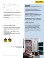
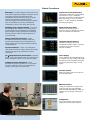
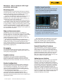
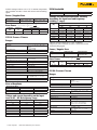
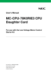
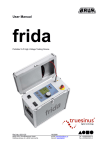
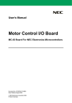
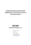
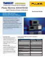
Fluke Norma 4000/5000 High Precision Power Analyzers Technical Data Reliable, highly accurate measurements for the test & development of power electronics Compact Fluke Norma Series power analyzers include the latest power measurement technology to assist engineers working with motors, inverters, lighting, power supplies, transformers and automotive components in making their products more efficient. Based on a patented high-bandwidth architecture, Fluke Norma Series power analyzers deliver precise measurements of single or threephase current and voltage, harmonics analysis, Fast Fourier Transformation (FFT) analysis, as well as calculations of power and other derived values. They provide class-leading accuracy and common mode rejection for any waveform, frequency, or phase shift. • • Fluke Norma 4000: Ideal for field testing, the Fluke Norma 4000 power analyzer offers easy and straight-forward operation. Features include: 1 to 3 power phases, 5.7” / 144 mm color display, harmonic analysis, FFT analysis, scope mode, vector diagram display, recorder function, Fluke NormaView PC software, and 4 MB RAM data memory. Fluke Norma 5000: Providing the highest bandwidth on the market, the Fluke Norma 5000 power analyzer is the ideal test and analysis tool for the development of frequency converters and lighting equipment. Features include: 1 to 6 power phases, optional internal printer, and all of the features and functionality of the Fluke Norma 4000 power analyzer described above. Fluke Norma Series power analyzers at a glance Fluke Norma 4000 Fluke Norma 5000 Number of Phases 1 or 3 3, 4 or 6 Bandwidth dc to 3 MHz or dc to 10 MHz depending on input module Basic Accuracy 0.2%, 0.1% or 0.03% depending on input modules Sampling Rate 0.33 MHz or 1 MHz depending on input modules Voltage Input Range 0.3 to 1000 V Current Input Range (direct, not via shunt) 0.03 mA – 20 A depending on input module Current Input Range via shunt Table Shunts on page 10 Display Color, 5.7“ / 144 mm - 320 x 240 pixel Measured data memory 4 MB Memory for Settings Standard Fast Fourier Transformation (FFT) To the 40th harmonic RS232 Interface Standard PI1 Process Interface (8 analog / impulse inputs and 4 analog outputs) Optional IEEE 488/GPIB Interface Optional Fluke NormaView PC Software (for data download, analysis) Standard Fluke Norma Series power analyzers -- optimum efficiency requires precise measurements Key Features • Compact, high precision power analyzers – easy to carry and save working space. • Simple user interface ensures easy, intuitive operation. • Standard configurations allow users to specify the exact functionality required for their own unique application. • Accurately display dynamic events on all phases at exactly the same point in time with simultaneous parallel acquisition of all phases. • All inputs are galvanically isolated to avoid short circuits in all applications. • Voltage, current and power harmonics up to the 40th. • FFT analysis, vector diagram display, recorder function and Digital Oscilloscope (DSO) mode included. • User-selectable average time – from 15 ms up to 3600 s – for dynamic measurements. • 4 MB on-board memory for storage of measured values. • RS232 and USB available as standard; optional IEEE 488/Ethernet available. • Optional process interface available to measure torque and speed with external sensors; includes four analog outputs for easy use on motor and drive applications. • 341 kHz or 1 MHz sample rates for detailed signal analysis. • Bandwidth from dc to 3 MHz / 10 MHz for reliable measurement precision. • Includes Fluke NormaView PC software for setup, data download, analysis. Fluke Norma Series power analyzers provide easy & reliable use in the field or as a bench unit in test laboratories. 2 Fluke Corporation Fluke Norma 4000/5000 power analyzers Applications Electric motors – Complete measurements of both electrical and mechanical power values with an uncertainty of only 0.1%. Through detailed spectrum analysis and dynamic torque calculation capabilities, switching losses caused by the inverter are accurately measured, and a thorough evaluation is made of torque transients and harmonics at higher frequencies. Inverter drive systems – Simultaneous measurement of all electrical and mechanical power parameters in the same time window enables users to observe the influence one component has on another, or on the whole system. Lighting systems – Unique bandwidth of up to 10 MHz and a high sampling rate up to 1 MHz provide detailed signal analysis at ballast outputs. A unique shunt technology enables power measurements at very high frequencies. Simultaneous measurement of input and output power provides instant calculation of ballast losses. Transformers – Synchronous six-phase power measurements enable highly accurate efficiency and loss calculations of large power transformers even at very low power factors. Synchronous multiphase resistance measurements are also possible of transformer coils. The internal formula editor enables voltage ratio calculations, and the combination of high-precision fundamental values and wide bandwidth provides detailed harmonics analysis. Basic Functions Automotive – Detailed analysis of all electrical and mechanical components installed in modern cars for developing strategies that help reduce fuel consumption or the increase the range of electric vehicles. Synchronous electrical input and mechanical output measurements provide complete data on the efficiency and losses of individual components as well as the whole drive system. Fast Fourier Transformation (FFT) Calculation of harmonics with graphical representation. Up to 3 harmonic spectrums are displayed simultaneously. Measured values: U, I, & P per phase. Order: 1st to 40th harmonics, maximum half sample frequency. Switching power supplies and UPS – Very wide bandwidth enables detailed and accurate power measurements in the switching link of switching power supplies. Unique coaxial shunt technology delivers precision results in high frequencies of several 100 kHz. Digital Oscilloscope (DSO) Simultaneous display of up to 3 measured values at sample level. Quick view of waveform and distortion. Charge pumps/boost converters – Wide measurement bandwidth combined with wide dynamic range enable precise measurements of charge pumps with very high switching frequency in the link circuit. Current transducers – Detect very small phase shift errors between the various current and voltage channels for support the calibration of current transducers. tan δ (dissipation factor) measurement – Measure power at very small power factors and calculate tan δ from voltage and current at very low loss angles. Calibration and test laboratories – High measurement accuracy enables use as a standard for power calibration and for the certification of voltage, current, power and distortion. Integration function (Energy) Simultaneous display of up to 6 configurable numeric values. Start/Stop conditions and positive negative direction available. Vector display Vector display of the fundamental for up to 6 signals. For easy testing of the right connection of the instrument and quick overview of the phase angle of each signal. Recorder function Display of average values over time for trend determination. RAM data memory Storing of sample and average values; setting of start and stop conditions. From the RAM approximately 4 MB are available for the storage of measured values. Configuration Set up the analyzer to measure and display data in the format required. 3 Fluke Corporation Fluke Norma 4000/5000 power analyzers Measure, test & analyze with high precision and ease Intuitive keypad operation Measuring system Fluke Norma Series power analyzers are very easy to use. With their simple keypad layout and large display, it is possible to select the desired screen and quickly see the important data. Fluke Norma 4000 and Fluke Norma 5000 power analyzers accurately measure current and voltage and calculate active, reactive and apparent power and calculate other derived values from these high-precision measurements. Accuracy is not affected by either the waveform shape or frequency over a wide range. Phase shift accuracy is maintained due to the input channel design. Harmonics are calculated up to half of the sampling rate. The DSO function represents measured input parameters as waveforms. Voltage and current can be measured directly via the instrument’s integrated voltage dividers and shunts. It is also possible to connect external voltage dividers as well as shunts or current probes for specific applications. Options such as additional interfaces, analogue inputs and outputs are also available. The analyzer firmware can be updated via the standard RS232 interface. High precision measurements Fluke Norma Series power analyzers are designed to measure signals in a wide frequency range from dc to MHz. The input stages are dc coupled and designed to handle high rise time signals. A zero and offset calibration against a stable voltage reference runs automatically over short time periods to stabilize the accuracy. All voltage and current channels are separated by a unique technology of barriers for high channel isolation and common mode rejection. This makes Fluke Norma Series power analyzers suitable for special applications, such as the switching waveforms present on variable frequency drives or high efficiency lighting loads. With the arrow keys, users can change phases or move the cursor to highlight individual fields, which can be accessed using the ENTER key. Settings can be changed to suit the application at hand. Configurations most used can be saved for later use. The input modules can handle up to 10 A or 20 A directly or measure current via wideband precision shunts. The available range of shunts enables measurements up to 1500 A and can be used in conjunction with all of the available input modules. Powerful NormaView PC software Non gapping The exceptionally high processing power enables precise measurements without gapping, ensuring good results even with rapidly changing signals. Longtime accuracy Fluke Norma Series power analyzers maintain high performance and reliable accuracy within the industry’s longest recommended recalibration interval of two years. This long interval reduces downtime and saves service costs. Standard configurations There are four different measuring channels available for each Fluke Norma Series power analyzer. For the highest level of flexibility and simplicity, you can choose from a variety of standard configurations. This enables users to select the power analyzer best suited to their application’s power measurement requirements. Each power phase module differs in basic accuracy, current measuring range, sampling frequency, and bandwidth. For detailed information about the available optional modular power phases, please refer to Page 6 of the specifications section. 4 Fluke Corporation Fluke Norma 4000/5000 power analyzers The Fluke NormaView software improves operation efficiency of the analyzers by enabling instrument setup settings to be saved and stored along with the measurement data. Instrument setups can be used for particular measurement tasks. Settings can be easily uploaded to the instrument with just a few mouse clicks. The software also enables quick and easy data download, analysis and report writing. Optional process interface The optional process interface can be used with both Fluke Norma 4000 and Fluke Norma 5000 power analyzers. It provides the simultaneous recording of torque (M), speed (N) and mechanical power (Pm) of up to four motors. Each of the eight inputs is switchable between analog (voltage) or digital (frequency) input. This interface provides synchronous capture at a sample rate of 34 kHz. The interface also provides four analog outputs, which are updated after every average interval. By inputting the additional analog and digital values it is possible to fully evaluate electrical and mechanical efficiency in real time. Specifications Ambient conditions Operating Temperature Range 5 °C to 35 °C (41 °F to 95 °F) Storage Temperature Range -20 °C to 50 °C (-4 °F to 122 °F) Housing Equipped with a solid metal case to meet stringent EMC requirements. Weight Fluke Norma 4000: Base unit approx. 5 kg (11 lb.) Fluke Norma 5000: Base unit approx. 7 kg (15 lb.) Dimensions (HxWxD) Fluke Norma 4000: 15 cm x 23.7 cm x 31.5 cm (5.9 in. x 9.3 in. x 12.4 in.) Fluke Norma 5000: 15 cm x 44.7 cm x 31.5 cm (5.9 in. x 17.6 in x 12.4 in.) Display 5.7“ / 144mm - 320 x 240 pixel User-selectable background lighting and contrast. Climatic Class B2 (according to IEC 60654-1) max. 85 % relative humidity, non-condensing. Mains Connection 85 to 264 V ac, 47 to 440 Hz, dc 120 to 370 V, approximately 40 VA ( 65 VA Fluke Norma 5000), European plug with switch. Measuring Terminals Safety sockets 4 mm, 2 for each input. External shunt connection over BNC socket. Operation Membrane keyboard with cursor – function keys and direct functions. Measured Values Non-gapping calculation of averaged values for each phase. In three phase system additionally calculation of total power and averaging of V and I of the three phases. The fundamental H01 will be calculated in synchronous mode also for these values. U RMS effective value, Urm rectified mean, Um mean value Up-, Up+, Upp peak values Ucf crest factor Ucf, Uff form factor Ufc fundamental content Uthd distortion factor DIN, IEC I RMS effective value, Irm rectified mean, Im mean value Ip-, Ip+, Ipp peak values Icf crest factor Icf, Iff form factor Ifc fundamental content Ithd distortion factor DIN, IEC P active power [W] Q reactive power [Var] S apparent power [VA] λ, cos ϕ phase angular Integral function for active power P, reactive power Q, apparent power S, voltage (Um) and current (Im), Number of digits 4 or 5 dependent on measured value. Frequency and Synchronization Range 0.2 Hz to sampling rate (102 kHz / 341 KHz / 1 MHz) Accuracy ±0.01 % • • • • • • Channels which can be selected: all U/I or external input. One of three low pass filter with different frequencies can be switched into the signal. The frequency is always visible on the top of the screen. The BNC synchronization socket on backside of the instrument can be used either as input or output. The input signals can be measured up to the sample rate of the power phase. The maximum level must not be higher then 50 V. The output signal is a pulsed 5 Volts TTL signal (frequency depends on the measured synch frequency). Configuration Memory Up to 15 user configurations can be saved into a permanent memory and reloaded later on. Changes that were not saved are lost after switching off the instrument. Standards and Safety Electrical Safety EN 61010-1 / 2nd Edition 1000 V CAT II (600 V CAT III) Degree of pollution 2, safety Class I EN 61558 for transformer EN 61010-2-031/032 for accessories Maximum Inputs For voltage inputs Measurement range 1000 Veff, 2 kVpeak For current inputs Measurement range 10 Aeff, 20 Apeak Test Voltages Mains input housing (earth ground connector): 1.5 KV ac Mains connection measuring inputs: 5.4 kV ac Measuring inputs housing: 3.3 kV ac Measuring input terminals: 5.4 kV Electromagnetic compatibility Emission: IEC 61326-1, EN 50081-1, EN 55011 Class B Immunity: IEC 61326-1 / Annex A (industrial sector), EN 50082-1 5 Fluke Corporation Fluke Norma 4000/5000 power analyzers Modular Power Phases The Fluke Norma 4000 power analyzer can be equipped with up to three power phases, and the Fluke Norma 5000 power analyzer can be equipped with up to six power phases. Users can select the type of power phase best suited for their application from a variety of optional power phases. Specifications vary depending on the model of the power phase. Each modular plug-in power phase consists of a voltage and a current measurement channel. Each measuring channel is available for each basic unit. However, only one kind of channel can be used per unit (see standard configurations). Fluke Norma 4000 (rear panel) Fluke Norma 5000 (rear panel) Power Phase Overview Channel Accuracy Current range Sampling rate PP42 0.2% (0.1% rg + 0.1% rg) 20 A 341 kHz 3 MHz 10 A 1 MHz 10 MHz PP50 0.1% (0.05% rg + 0.05% rg) PP52 PP54 0.03% (0.02% rg + 0.01% rg, at 45 - 65 Hz) PP64 20 A 341 kHz 3 MHz 10 A 341 kHz 3 MHz 10 A 341 kHz 3 MHz Voltage and current depending on the input level at 45 – 65 Hz frequency range PP42 Power Phase Ranges Input level Sum limit of error V in % in % in % 100 0.20 0.20 50 0.30 0.30 30 0.43 0.43 Voltage 8 ranges: Bandwidth 0.3 – 1 – 3 – 10 – 30 – 100 – 300 – 1000 V Vpeak = 2 x range Sum limit of error I Input impedance: 2 MOhm / 20 pF 10 1.10 1.10 CMR common mode rejection: 120 dB at 100 kHz 5 2.10 2.10 Current (20A) 6 ranges: 3.43 3.43 1 10.10 10.10 60 – 200 mA – 0.6 – 2 – 6 – 20 A Ipeak = 2 x range PP42 Bandwidth Input impedance with integrated shunts: Ranges 60, 200 mA: 1 Ohm typ. Ranges 0.6, 2 A: 0.2 Ohm typ. Ranges 6, 20 A: 0.02 Ohm typ. Current overload: max. 25 A continuous 30 A < 5 sec / 15 sec no load 100 A < 0.1 s / 30 sec no load Bandwidth –3 dB Input for external shunt or probe: BNC terminal: 100 kOhm / 30 pF 30 – 100 mV – 0.3 – 1 – 3- 10 V Overload: max. 20 Vrms CMR common mode rejection: 120 dB at 100 kHz Error of Amplitude Basic accuracy PP42 Sum limit of error 3 V and I via BNC I direct measured 3 MHz 0.5 MHz Voltage and current measurement accuracy depending on the input level and the frequency (reading + range) Frequency [Hz] Limits of error in % Input level in % 100 75 50 25 0 - 1,000 +/- 0.20 +/- 0.23 +/- 0.30 +/- 0.50 2,000 +/- 0.29 +/- 0.34 +/- 0.44 +/- 0.73 5,000 +/- 0.41 +/- 0.48 +/- 0.61 +/- 1.02 10,000 +/- 0.50 +/- 0.58 +/- 0.75 +/- 1.25 +/- 1.63 V I 20,000 +/- 0.65 +/- 0.76 +/- 0.98 Error of Range 0.1% 0.1% 50,000 +/- 0.84 +/- 0.99 +/- 1.27 +/- 2.12 Error of Reading 0.1% 0.1% 100,000 +/- 1.00 +/- 1.17 +/- 1.50 +/- 2.50 6 Fluke Corporation Fluke Norma 4000/5000 power analyzers Valid for averaged values at 23 ± 0,5 °C ambient temperature, sine waveform and after 1 hour turn on time with measuring signal. Power / Angular Error PP42 Between VV and I BNC Between V and IShunt Angular Error 0.005° +0.005° / kHz 0.005° +0.015° / kHz Aliasing filter OFF Bandwidth –3 dB V and I via BNC I direct measured 10 MHz 1 MHz Voltage and current measurement accuracy depending the input level and frequency (reading + range) Frequency [Hz] ¥ Ea S ´ Ep in % of rdg = ± ¦Ev + Ei + µ § P ¶ Error Power PP50 Bandwidth Frequency [Hz] Input level [%] Limit of error in % Lamda=1 Lamda=0.1 Lamda=0.01 45 - 65 100 0.33 0.34 1.06 0 - 1,000 PP50 Power Phase Ranges Voltage 8 ranges: 0.3 – 1 – 3 – 10 – 30 – 100 – 300 – 1000 V Vpeak = 2 x range Input impedance: 2 MOhm / 20 pF CMR common mode rejection: 120 dB at 100 kHz Limits of error in % Input level in % 100 75 50 25 +/- 0.10 +/- 0.12 +/- 0.15 +/- 0.25 +/- 0.36 2,000 +/- 0.15 +/- 0.17 +/- 0.22 5,000 +/- 0.20 +/- 0.24 +/- 0.31 +/- 0.51 10,000 +/- 0.25 +/- 0.29 +/- 0.38 +/- 0.63 20,000 +/- 0.33 +/- 0.38 +/- 0.49 +/- 0.81 50,000 +/- 0.42 +/- 0.50 +/- 0.64 +/- 1.06 100,000 +/- 0.50 +/- 0.58 +/- 0.75 +/- 1.25 Valid for averaged values at 23 ± 0.5 °C ambient temperature, sine waveform and after 1 hour turn on time with measuring signal. Power / Angular Error PP50 Between V and I BNC Between V and IShunt Angular Error 0.005° +0.005° / kHz 0.005° +0.010° / kHz Aliasing filter OFF Current (10A) 6 ranges: 30 – 100 mA – 0.3 – 1 – 3 – 10 A Ipeak = 2 x range Input impedance with integrated shunts: Ranges 30, 100 mA: 1.4 Ohm typ. Ranges 0.3, 1 A: 0.25 Ohm typ. Ranges 3, 10 A: 0.025 Ohm typ. Current overload: Error Power ¥ Ea S ´ Ep in % of rdg = ± ¦Ev + Ei + µ § P ¶ Frequency [Hz] Input level [%] Lamda=1 Limit of error in % Lamda=0.1 Lamda=0.01 45 - 65 100 0.16 0.19 1.02 max. 15 A continuous 30 A < 5 sec / 15 sec no load 100 A < 0.1 s / 30 sec no load Input for external shunt or probe: BNC terminal: 100 kOhm / 30 pF 30 – 100 mV – 0.3 – 1 – 3- 10 V Overload: max. 20 Vrms CMR common mode rejection: 120 dB at 100 kHz PP52 Power Phase Ranges Voltage Error of Amplitude 8 ranges: 0.3 – 1 – 3 – 10 – 30 – 100 – 300 – 1000 V Vpeak = 2 x range Input impedance: 2 MOhm / 20 pF CMR common mode rejection: 120 dB at 100 kHz Basic accuracy PP50 Sum limit of error V I Error of range 0.05% 0.05% Error of reading 0.05% 0.05% Current (20A) 6 ranges: 60 – 200 mA – 0.6 – 2 – 6 – 20 A Ipeak = 2 x range Input impedance with integrated shunts: Voltage and current depending on the input level at 45 – 65 Hz frequency range Ranges 60, 200 mA: 1 Ohm typ. Ranges 0.6, 2 A: 0.2 Ohm typ. Ranges 6, 20 A: 0.02 Ohm typ. Current overload: max. 25 A continuous 30 A < 5 sec / 15 sec no load 100 A < 0.1 s / 30 sec no load Input level Sum limit of error V Sum limit of error I in % in % in % 100 0.10 0.10 50 0.15 0.15 Input for external shunt or probe: 30 0.22 0.22 BNC terminal: 10 0.55 0.55 100 kOhm / 30 pF 30 – 100 mV – 0.3 – 1 – 3- 10 V 5 1.05 1.05 Overload: max. 20 Vrms 3 1.72 1.72 CMR common mode rejection: 120 dB at 100 kHz 1 5.05 5.05 7 Fluke Corporation Fluke Norma 4000/5000 power analyzers Error of Amplitude PP54 Power Phase Basic accuracy PP52 V I Ranges Error of range 0.05% 0.05% Voltage Error of reading 0.05% 0.05% 8 ranges: 0.3 – 1 – 3 – 10 – 30 – 100 – 300 – 1000 V Vpeak = 2 x range Input impedance: 2 MOhm / 20 pF CMR common mode rejection: 120 dB at 100 kHz Sum limit of error Voltage and current depending on the input level at 45 – 65 Hz frequency range Input level Sum limit of error V Sum limit of error I in % in % in % Current (10A) 100 0.10 0.10 6 ranges: 50 0.15 0.15 30 0.22 0.22 10 0.55 0.55 5 1.05 1.05 3 1.72 1.72 1 5.05 5.05 30 – 100 mA – 0,3 – 1 – 3 – 10 A Ipeak = 2 x range; max level 150% at sine wave (limit of error as at 100%). Input impedance with integrated shunts: Ranges 30, 100 mA: 1.4 Ohm typ. Ranges 0.3, 1 A: 0.25 Ohm typ. Ranges 3, 10 A: 0.025 Ohm typ. Current overload: max. 15 A continuous 30 A < 5 sec / 15 sec no load PP52 Bandwidth Bandwidth –3 dB 100 A < 0.1 s / 30 sec no load V and I via BNC I direct measured Input for external shunt or probe: 3 MHz 1 MHz BNC terminal: 100 kOhm / 30 pF 30 – 100 mV – 0.3 – 1 – 3- 10 V Overload: max. 20 Vrms CMR common mode rejection: 120 dB at 100 kHz Voltage and current measurement accuracy depending the input level and frequency (reading + range) Frequency [Hz] Error of Amplitude Limits of error in % Basic accuracy PP54 Input level in % 0 - 1,000 100 75 50 25 V I +/- 0.10 +/- 0.12 +/- 0.15 +/- 0.25 Error of range 0.05% 0.05% Error of reading 0.05% 0.05% 2,000 +/- 0.15 +/- 0.17 +/- 0.22 +/- 0.36 5,000 +/- 0.20 +/- 0.24 +/- 0.31 +/- 0.51 10,000 +/- 0.25 +/- 0.29 +/- 0.38 +/- 0.63 20,000 +/- 0.33 +/- 0.38 +/- 0.49 +/- 0.81 50,000 +/- 0.42 +/- 0.50 +/- 0.64 +/- 1.06 100,000 +/- 0.50 +/- 0.58 +/- 0.75 +/- 1.25 Valid for averaged values at 23 ± 0.5 °C ambient temperature, sine waveform and after 1 hour turn on time with measuring signal. Power / Angular Error PP52 Between VV and I BNC Between V and IShunt Angular Error 0.005° +0.005° / kHz 0.005° +0.015° / kHz Aliasing filter OFF Sum limit of error Voltage and current depending on the input level at 45 – 65 Hz frequency range Input level Sum limit of error V Sum limit of error I in % in % in % 100 0.10 0.10 50 0.15 0.15 30 0.22 0.22 10 0.55 0.55 5 1.05 1.05 3 1.72 1.72 1 5.05 5.05 PP54 Bandwidth Error Power ¥ Ea S ´ Ep in % of rdg = ± ¦Ev + Ei + µ § P ¶ Bandwidth –3 dB Frequency [Hz] Input level [%] Lamda=1 Lamda=0.1 Lamda=0.01 45 - 65 100 0.16 0.19 1.02 8 Fluke Corporation Limit of error in % Fluke Norma 4000/5000 power analyzers V and I via BNC I direct measured 3 MHz 1 MHz Voltage and current measurement accuracy depending on the input level and the frequency (reading + range) Frequency [Hz] Limits of error in % Input level in % 100 75 50 25 0 - 1,000 +/- 0.10 2,000 +/- 0.15 +/- 0.12 +/- 0.15 +/- 0.25 +/- 0.17 +/- 0.22 +/- 0.36 5,000 +/- 0.20 +/- 0.24 +/- 0.31 +/- 0.51 10,000 +/- 0.25 +/- 0.29 +/- 0.38 +/- 0.63 20,000 +/- 0.33 +/- 0.38 +/- 0.49 +/- 0.81 50,000 +/- 0.42 +/- 0.50 +/- 0.64 +/- 1.06 100,000 +/- 0.50 +/- 0.58 +/- 0.75 +/- 1.25 Error of Amplitude Basic accuracy PP64 Sum limit of error V I Error of range 0.02% 0.02% Error of reading 0.01% 0.01% Voltage and current depending on the input level at 45 – 65 Hz frequency range Input level Sum limit of error V Sum limit of error I in % in % in % 100 0.03 0.03 50 0.05 0.05 30 0.08 0.08 10 0.21 0.21 5 0.41 0.41 3 0.68 0.68 1 2.01 0.03 Valid for averaged values at 23 ± 0.5 °C ambient temperature, sine waveform and after 1 hour turn on time with measuring signal. Power / Angular Error PP54 Between V and I BNC Between V and IShunt Angular Error 0.005° +0.005° / kHz 0.020° + 0.010° / kHz Aliasing filter OFF ¥ Ea S ´ Ep in % of rdg = ± ¦Ev + Ei + µ § P ¶ Error Power Frequency [Hz] Input level [%] Limit of error in % Lamda=1 Lamda=0.1 Lamda=0.01 45 - 65 100 0.16 0.19 1.02 PP64 Power Phase PP64 Bandwidth Bandwidth –3dB V and I via BNC I direct measured 3 MHz 1 MHz Voltage and current measurement accuracy depending on the input level and the frequency (reading + range) Frequency [Hz] Limits of error in % Input level in % 100 75 50 25 0 - 45 +/- 0.05 +/- 0.06 +/- 0.07 +/- 0.11 +/- 0.09 45-65 +/- 0.03 +/- 0.04 +/- 0.05 Ranges 65 - 1,000 +/- 0.05 +/- 0.06 +/- 0.07 +/- 0.11 Voltage 2,000 +/- 0.16 +/- 0.18 +/- 0.23 +/- 0.37 0.3 – 1 – 3 – 10 – 30 – 100 – 300 – 1000 V Vpeak = 2 x range 5,000 +/- 0.29 +/- 0.34 +/- 0.44 +/- 0.72 10,000 +/- 0.40 +/- 0.47 +/- 0.60 +/- 0.99 20,000 +/- 0.52 +/- 0.61 +/- 0.78 +/- 1.29 Input impedance: 2 MOhm / 20 pF 50,000 +/- 0.68 +/- 0.79 +/- 0.1.01 +/- 1.68 CMR common mode rejection: 120 dB at 100 kHz 100,000 +/- 0.80 +/- 0.93 +/- 1.20 +/- 1.99 8 ranges: Current (10A) 6 ranges: 30 – 100 mA – 0,3 – 1 – 3 – 10 A Ipeak = 2 x range; max level 150% at sine wave (limit of error as at 100%). signal. Power / Angular Error / Between V and I Input impedance with integrated shunts: Ranges 30, 100 mA: 1.4 Ohm typ. Ranges 0.3, 1 A: 0.25 Ohm typ. Ranges 3, 10 A: 0.025 Ohm typ. Current overload: Valid for averaged values at 23 ± 0.5 °C ambient temperature, sine waveform and after 1 hour turn on time with measuring PP64 45-65Hz, antialiasing filter on 10Hz- 100kHz antialiasing filter off Angular Error 0.0025° 0.005° +0.005°/kHz max. 15 A continuous 30 A < 5 sec / 15 sec no load 100 A < 0.1 s / 30 sec no load Input for external shunt or probe: BNC terminal: 100 kOhm / 30 pF 30 – 100 mV – 0.3 – 1 – 3- 10 V Overload: max. 20 Vrms CMR common mode rejection: 120 dB at 100 kHz 9 Fluke Corporation Fluke Norma 4000/5000 power analyzers ¥ Ea S ´ Ep in % of rdg = ± ¦Ev + Ei + µ § P ¶ Error Power Frequency [Hz] Input level [%] Lamda=1 Limit of error in % Lamda=0.1 Lamda=0.01 45 - 65 100 0.05 0.07 0.51 Ordering Information Fluke Norma 4000 Basic Configuration Fluke Norma 4000 High Precision Power Analyzer Fluke Norma 5000 Basic Configuration Basic configuration includes: • Power supply cable • 5.7“ / 144 mm Color display • RS232/USB interface for data download • Space for three power-phases and options • Fluke NormaView PC software • Color user’s manual • Test certificate with measurement values full point is : Test certificate with measurement values Fluke Norma 5000 High Precision Power Analyzer Recommended Accessories Shunts The input modules can take up to 10 A or 20 A directly or measure current via wideband precision shunts. The available range of shunts enable measurements up to 1500 A and can be used in conjunction with all of the available input modules. Order Number Description 3024677 32 A Planar Shunt, Imax 32A 3024689 Cables for 32 A Planar Shunt 3024886 10 A Triaxial Shunt with Cables, Imax 30A (10 mΩ, 0 to 2 MHz) 3024899 30 A Triaxial Shunt with Cables, Imax 100A (1mΩ, 0 to 2 MHz) 3024847 100 A Shunt with Cables, Imax 300A (0,2 mΩ, 0 to 1 MHz) 3024858 150 A Shunt with Cables, Imax 450A (0.5 mΩ, 0 to 0.5 MHz) 3024864 300 A Shunt with Cables, Imax 1000A (0,06 mΩ, 0 to 0,5 MHz) 3024873 500 A Shunt with Cables, Imax 1500A (0,06 mΩ, 0 to 0.2 MHz) 3024692 LG Shunt Cables for High Current Shunts 3313059 Fluke Norma 4000,19 inch rack mount kit with handles 3313067 Fluke Norma 5000,19 inch rack mount kit with handles Cables & Adaptors Order Number Description 3024661 Measurement Cable Set (for one power phase) 3024704 Fluke Norma WYE Adaptor (external accessory box) Printer Accessories Order Number Description 3024650 Printer Cable for Fluke Norma 5000 and Fluke Norma 4000 (RS232-Centronics) 3024781 Norma Printer Paper All accessories have a two-year warranty. 10 Fluke Corporation Fluke Norma 4000/5000 power analyzers Basic configuration includes: • Power supply cable • 5.7“ / 144 mm Color display • Internal printer (optional) • RS232/USB interface for data download • Space for six power-phases and options • Fluke NormaView PC software • Color user’s manual • Test certificate with measurement values full point is : Test certificate with measurement values Standard configurations Order number Short Description Description Power phases type 3108534 Fluke-N4K 1PP42 Fluke-Norma 4000, single phase with PP42 power phase input module ● 1 3108541 Fluke-N4K 3PP42 Fluke-Norma 4000, three phase with 3xPP42 power phase input modules ● 3 3108552 Fluke-N4K 3PP42I Fluke-Norma 4000, three phase with 3xPP42 power phase input modules with IEEE488 / Ethernet interface ● 3 ● 3108565 Fluke-N4K 3PP42IP Fluke-Norma 4000, three phase with 3xPP42 power phase input modules with IEEE488 / Ethernet interface and analog / digital output channels ● 3 ● 3110957 Fluke-N4K 3PP42B Fluke-Norma 4000, three phase with 3xPP42 power phase input modules with current binding post ● 3 3110969 Fluke-N4K 3PP42IB Fluke-Norma 4000, three phase with 3xPP42 power phase input modules with current binding post with IEEE488 / Ethernet interface ● 3 ● 3110978 Fluke-N4K 3PP42IPB Fluke-Norma 4000, three phase with 3xPP42 power phase input modules with current binding post with IEEE488 / Ethernet interface and analog / digital output channels ● 3 ● 3108576 Fluke-N4K 3PP50 Fluke-Norma 4000, three phase with 3xPP50 power phase input modules ● 3 3108583 Fluke-N4K 3PP50I Fluke-Norma 4000, three phase with 3xPP50 power phase input modules with IEEE488 / Ethernet interface ● 3 ● 3108590 Fluke-N4K 3PP50IP Fluke-Norma 4000, three phase with 3xPP50 power phase input modules with IEEE488 / Ethernet interface and analog / digital output channels ● 3 ● 3312894 Fluke-N4K 3PP52IB Fluke-Norma 4000, three phase with 3xPP52 power phase input modules with current binding post with IEEE488 / Ethernet interface 3 ● 3108601 Fluke-N4K 3PP54I Fluke-Norma 4000, three phase with 3xPP54 power phase input modules with IEEE488 / Ethernet interface ● 3 ● 3108612 Fluke-N4K 3PP54IP Fluke-Norma 4000, three phase with 3xPP54 power phase input modules with IEEE488 / Ethernet interface and analog / digital output channels ● 3 ● 3108620 Fluke-N5K 3PP50 Fluke-Norma 5000, three phase with 3xPP50 power phase input modules ● 3 3108635 Fluke-N5K 3PP50I Fluke-Norma 5000, three phase with 3xPP50 power phase input modules with IEEE488 / Ethernet interface ● 3 ● 3108647 Fluke-N5K 3PP50IP Fluke-Norma 5000, three phase with 3xPP50 power phase input modules with IEEE488 / Ethernet interface and analog / digital output channels ● 3 ● 3108658 Fluke-N5K 3PP54 Fluke-Norma 5000, three phase with 3xPP54 power phase input modules ● 3 3108664 Fluke-N5K 3PP54I Fluke-Norma 5000, three phase with 3xPP54 power phase input modules with IEEE488 / Ethernet interface ● 3 3312934 Fluke-N5K 3PP54R Fluke-Norma 5000, three phase with 3xPP54 power phase input modules and printer ● 3 3108673 Fluke-N5K 3PP54IP Fluke-Norma 5000, three phase with 3xPP54 power phase input modules with IEEE488 / Ethernet interface and analog / digital output channels ● 3 ● 3312941 Fluke-N5K 3PP54IR Fluke-Norma 5000, three phase with 3xPP54 power phase input modules with IEEE488 / Ethernet interface and printer ● 3 ● 3108686 Fluke-N5K 3PP64 Fluke-Norma 5000, three phase with 3xPP64 power phase input modules ● 3 3108699 Fluke-N5K 3PP64I Fluke-Norma 5000, three phase with 3xPP64 power phase input modules with IEEE488 / Ethernet interface ● 3 ● 3108702 Fluke-N5K 3PP64IP Fluke-Norma 5000, three phase with 3xPP64 power phase input modules with IEEE488 / Ethernet interface and analog / digital output channels ● 3 ● 3312952 Fluke-N5K 3PP64R Fluke-Norma 5000, three phase with 3xPP64 power phase input modules and printer ● 3 3312965 Fluke-N5K 3PP64IR Fluke-Norma 5000, three phase with 3xPP64 power phase input modules with IEEE488 / Ethernet interface and printer ● 3 ● 3312976 Fluke-N5K 3PP64IPR Fluke-Norma 5000, three phase with 3xPP64 power phase input modules with IEEE488 / Ethernet interface and analog / digital output channels and printer ● 3 ● ● 3108716 Fluke-N5K 4PP54 Fluke-Norma 5000, three phase with 4xPP54 power phase input modules ● 4 3108725 Fluke-N5K 4PP54IP Fluke-Norma 5000, three phase with 4xPP54 power phase input modules with IEEE488 / Ethernet interface and analog / digital output channels ● 4 ● ● 3312929 Fluke-N5K 6PP42IB Fluke-Norma 5000, three phase with 6xPP42 power phase input modules with current binding post with IEEE488 / Ethernet interface 6 ● PP42 PP50 PP52 PP54 No. of phases PP64 ● ● IEEE488/ Process Printer LAN interface ● ● ● ● ● ● ● ● ● ● ● ● ● See Recommended Accessories on Page 10. 11 Fluke Corporation Fluke Norma 4000/5000 power analyzers Standard configurations Order number Short Description Description 3313044 Fluke-N5K 6PP42IBR Fluke-Norma 5000, three phase with 6xPP42 power phase input modules with current binding post with IEEE488 / Ethernet interface and printer 3312918 Fluke-N5K 6PP50IP Fluke-Norma 5000, three phase with 6xPP50 power phase input modules with IEEE488 / Ethernet interface and analog / digital output channels 3313003 Fluke-N5K 6PP50IR Fluke-Norma 5000, three phase with 6xPP50 power phase input modules with IEEE488 / Ethernet interface and printer 3313015 Fluke-N5K 6PP50IPR Fluke-Norma 5000, three phase with 6xPP50 power phase input modules with IEEE488 / Ethernet interface and analog / digital output channels and printer 3312907 Fluke-N5K 6PP50I Fluke-Norma 5000, three phase with 6xPP50 power phase input modules with IEEE488 / Ethernet interface 3108733 Fluke-N5K 6PP54I Fluke-Norma 5000, three phase with 6xPP54 power phase input modules with IEEE488 / Ethernet interface 3108740 Fluke-N5K 6PP54IP 3312983 Power phases type PP42 PP50 PP52 PP54 No. of phases IEEE488/ Process Printer LAN interface PP64 ● 6● ● ● 6 ● ● 6 ● 6 ● 6 ● ● 6 ● Fluke-Norma 5000, three phase with 6xPP54 power phase input modules with IEEE488 / Ethernet interface and analog / digital output channels ● 6 ● Fluke-N5K 6PP54IR Fluke-Norma 5000, three phase with 6xPP54 power phase input modules with IEEE488 / Ethernet interface and printer ● 6 ● 3312990 Fluke-N5K 6PP54IPR Fluke-Norma 5000, three phase with 6xPP54 power phase input modules with IEEE488 / Ethernet interface and analog / digital output channels and printer ● 6 ● 3108757 Fluke-N5K 6PP64I Fluke-Norma 5000, three phase with 6xPP64 power phase input modules with IEEE488 / Ethernet interface ● 6 ● 3108769 Fluke-N5K 6PP64IP Fluke-Norma 5000, three phase with 6xPP64 power phase input modules with IEEE488 / Ethernet interface and analog / digital output channels ● 6 ● 3313026 Fluke-N5K 6PP64IR Fluke-Norma 5000, three phase with 6xPP64 power phase input modules with IEEE488 / Ethernet interface and printer ● 6 ● 3313032 Fluke-N5K 6PP64IPR Fluke-Norma 5000, three phase with 6xPP64 power phase input modules with IEEE488 / Ethernet interface and analog / digital output channels and printer ● 6 ● ● ● ● ● ● ● ● ● ● ● ● ● ● ● Fluke. Keeping your world up and running.® Fluke Corporation PO Box 9090, Everett, WA USA 98206 Fluke Europe B.V. PO Box 1186, 5602 BD Eindhoven, The Netherlands For more information call: In the U.S.A. (800) 443-5853 or Fax (425) 446-5116 In Europe/M-East/Africa +31 (0) 40 2675 200 or Fax +31 (0) 40 2675 222 In Canada (800) 36-FLUKE or Fax (905) 890-6866 From other countries +1 (425) 446-5500 or Fax +1 (425) 446-5116 Web access: http://www.fluke.com © Copyright 2008 Fluke Corporation. All rights reserved. Printed in the Netherlands 07/2008. Data subject to alteration without notice. 12 Fluke Corporation Fluke Norma 4000/5000 power analyzers Pub_ID 11259-eng rev. 4