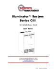
1
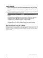
INSTALLATION & USER’S
GUIDE
1000W - 2800W SINGLE PHASE
Series EM
EMERGENCY LIGHTING CENTRAL INVERTER
Myers Power Products, Inc.
44 South Commerce Way, Bethlehem, PA 18017
1-800-526-5088 • (610) 868-3500 • Fax: (610) 868-8686
Service: (610) 868-5400
www.myerspowerproducts.com
114794C - EM Manual
This unit contains LETHAL VOLTAGES. All repairs and service should be performed by
AUTHORIZED SERVICE PERSONNEL ONLY! There are NO USER SERVICEABLE
PARTS inside this unit.
IMPORTANT SAFEGUARDS
When using electrical equipment, you should always follow basic safety
precautions, including the following:
1.
READ AND FOLLOW ALL SAFETY
INSTRUCTIONS.
2. Do not install the system outdoors.
3. Do not install near gas or electric heaters or in other high-temperature
locations.
4. Use caution when servicing batteries. Depending on battery type, batteries
contain either acid or alkali and can cause burns to skin and eyes. If
battery fluid is spilled on skin or in the eyes, flush with fresh water and
contact a physician immediately.
5. Equipment should be mounted in locations where it will not be subjected to
tampering by unauthorized personnel.
6. The use of accessory equipment not recommended by Manufacturer may
cause an unsafe condition and void the warranty.
7. Do not use this equipment for other than its intended use.
8. Qualified service personnel must perform all servicing of this equipment.
SAVE THESE INSTRUCTIONS
The installation and use of this product must comply with all national, federal,
state, municipal, or local codes that apply. If you need help, please call
Service. 610-868-5400
1
114794C—Install/User Manual
CAUTION
READ ENTIRE MANUAL AND REVIEW ALL DOCUMENTATION BEFORE ATTEMPTING SYSTEM
INSTALLATION!
FOR SERVICE or INSTALLATION INFORMATION
TELEPHONE: (610) 868-5400 (24 HR. HOTLINE)
FAX: (610) 954-8227
FOR YOUR PROTECTION....
PLEASE COMPLETE AND RETURN WARRANTY REGISTRATION CARD IMMEDIATELY.
CAUTION
Do not drill the cabinet; drilling cabinet will void factory warranty; drill filings may
damage the unit and keep it from operating. If you need larger knockouts, use a
chassis punch to punch out the appropriate knockout.
2
114794C—Install/User Manual
TABLE OF CONTENTS
Page(s)
SECTION 1
Safety Warning…………………………………………………………………………….… 4
Battery Storage
SECTION 2
Introduction……..…………………………………………………………………………….5-6
SECTION 3
Before installing the system…..……………………………………………………...……7-12
System Dimensions and Weights
Location Guidelines
Storage and operating Environment
Installation overview
SECTION 4
AC input & AC output Installation…….…………………………………………………13-15
SECTION 5
Installing batteries and DC wiring……………………………….……………………....16-21
Safety instructions
Before installing the batteries
Installing and connecting the batteries
Replacing the batteries
SECTION 6
Startup and shutdown procedure……..…………………………………….…….…..…22-23
SECTION 7
Operation…….…….…………….…………………………………………………………….24
SECTION 8
Keypad/Front Display Panel………………………..……………………………………..25-28
Control panel keypads
Meter functions
Control functions
Program functions
Automatic tests
SECTION 9
Specifications…….…………….…………………………………………………………….29
SECTION10
Maintenance and service…..…..……………….…………………………………………30-31
Trouble shooting chart
SECTION 11
Warranty……..…………………………………….……………………………..….……….32-33
3
114794C—Install/User Manual
SECTION 1
SAFETY WARNINGS
Read the following precautions before you install this emergency lighting system.
IMPORTANT SAFETY INSTRUCTIONS
SAVE THESE INSTRUCTIONS. This manual contains important instructions that you should
follow during installation and maintenance of the system and batteries. Please read all instructions
before operating the equipment and save this manual for future reference.
DANGER
This system contains LETHAL VOLTAGES. AUTHORIZED SERVICE PERSONNEL should
perform all repairs and service ONLY. There is NO USER SERVICEABLE PARTS inside the
Emergency lighting power supply.
WARNING
• Do not install the system outdoors.
• Do not install near gas or electric heaters or in other high-temperature locations.
• Use caution when servicing batteries. Battery acid can cause burns to skin and eyes. If acid is
spilled on skin or in the eyes, flush with fresh water and contact a physician immediately.
• Equipment should be mounted in locations where it is not readily subjected to tampering by
unauthorized personnel.
• The use of accessory equipment not recommended by the manufacturer may cause an unsafe
condition.
• Do not use this equipment for other than intended use.
• Only qualified service personnel (such as a licensed electrician) should perform the system and
battery installation and initial startup. Risk of electrical shock.
BATTERY STORAGE
This shipment contains rechargeable, maintenance free batteries. They must be stored properly to
assure proper operation upon installation. Therefore, please follow the following guidelines when
storing batteries:
•
•
•
•
4
Store in clean, dry and cool location. While it is safe to store batteries in environments of -18 to
40 degrees C (0 to 104 degrees F), it is recommended that you do not store at temperatures
above 30 degrees C (86 degrees F). The warmer the ambient temperature, the higher the self
discharge rate of the battery. This will require more frequent recharge of the individual batteries
until they are placed in service.
Avoid storing in direct sunlight or in front of or near heaters, heat duct or other sources of heat.
Do not store directly on concrete structures. Always store on wooden pallets or metal shelves
near floor level.
Place the batteries in service within 180 days of receipt. If you cannot place the batteries in
service within the 180 days, then the batteries must be recharged every 180 days, (more
frequently if stored at elevated temperatures) while in storage. Failure to do so will void the
warranty and may cause irreversible damage to the battery.
114794C—Install/User Manual
SECTION 2
INTRODUCTION
Keep this Guide in the folder mounted inside the unit.
This unit is a microprocessor controlled PWM (Pulse Width Modulated) pure sine wave based DC to
AC power inverter utilizing IGBT technology. It integrates a fully automatic 3-rate battery charger, a
solid-state transfer system, control circuitry, self testing and recording digital meter display, and
maintenance free sealed lead calcium type batteries. The system components are carefully matched
to make the unit a completely self-contained, fully automatic standby power source for operation on
all types of lighting loads. The batteries are sized and tested per UL-924 and Life Safety Code ANSI /
NFPA 101, providing emergency power for a minimum of 90 minutes.
If the duration of a power failure is greater than the batteries storage capability, the inverter will
automatically shut down when the battery voltage reaches 85% of the nominal DC voltage. This
feature protects the battery from being permanently damaged from a deep discharge that could cause
cell reversal. This battery protection feature is called "Low Voltage Disconnect" or L.V.D.
When the AC power is restored after a full discharge, the system will be ready for another power
failure within 24hrs. If another power failure occurs before the 24-hour recharge time, the run time
will be decreased.
The front panel display incorporates a 4 x 20 vacuum fluorescent display and a 4-button keypad. All
user interface functions are available from the front panel assembly.
Utilizing a small footprint, this unit is for use with any lighting load including quartz, HID,
incandescent, and fluorescent and halogen.
HOW TO USE THIS MANUAL
This manual tells you how to install, start, operate, and communicate with your unit and lets you know
how to get more information for special situations.
Please record your unit’s part number, serial number, and model number below. You can find these
numbers on the label on the backside of the cabinet panel.
Part Number __________________________
Serial Number __________________________
Model Number ___________________________
5
114794C—Install/User Manual
Record Keeping
An on-site permanent log of the inspection, testing, and maintenance of the emergency
electrical power supply system shall be maintained in accordance with this manual.
The log shall include:
The date on which the inspection, testing, and maintenance exercise was carried out.
The name of the person(s) who performed the inspection, testing, and maintenance.
A note of any unsatisfactory condition observed or discovered, and the steps taken to
correct the condition.
Service and Support
We are committed to outstanding customer service. A service technician is
available 24 hours a day, 365 days a year. Service is also available 24 hours a day to give you
access to technical notes and product information.
NOTE: Please have your unit’s Serial and Part numbers available when you call; this number is
located on the backside of the cabinet panel.
6
114794C—Install/User Manual
SECTION 3
BEFORE INSTALLING THE SYSTEM
System Dimensions and Weights
Required Clearance
Top – 6” (15.24 cm)
Sides – 2” (5.1 cm)
Front – 36” (91.4 cm)
Figure 3.1 1000W System Dimensions
Required Clearance
Top – 6” (15.24 cm)
Sides – 2” (5.1 cm)
Front – 36” (91.4 cm)
Figure 3.2 1600W-2200W System Dimensions
7
114794C—Install/User Manual
Required Clearance
Top – 6” (15.24 cm)
Sides – 2” (5.1 cm)
Front – 36” (91.4 cm)
Figure 3.3 2800W System Dimensions
Table 3.1 System weight [in lbs. (kg)]
8
1000W
1600W
2200W
2800W
Inverter
Cabinet
121 (55)
165 (75)
174 (79)
203 (92)
Batteries
160 (73)
240 (109)
320 (146)
400 (182)
System
Total
281 (128)
405 (184)
494 (225)
603 (274)
114794C—Install/User Manual
Knockout Diameter: 7/8” / 1-1/8” (2.2 cm / 2.9 cm)
Figure 3.4 Conduit Knockout Dimensions
Stacking Detail for Systems with a Battery Cabinet
Figure 3.5 Cabinet Stacking Detail (1600W – 2800W)
9
114794C—Install/User Manual
Location Guidelines
Keep the following guidelines in mind when choosing the location for your system and batteries:
•
Verify that the environment meets the requirements in “Storage and Operating Environment” on
page 11. The environment can affect the reliability and performance of both the unit and the
batteries.
•
Choose a permanent location for the unit. Attempting to move the unit after you have installed the
batteries can damage the batteries and the cabinet.
CAUTION
Do not move the unit after you install the batteries. If you do, the unit and batteries may be
damaged.
CEC (Canadian Electric Code) requires the unit to be located in a service room. If the room is
equipped with a sprinkler system, the unit must be provided with sprinkler proof cover.
The system should be connected to the emergency generator, if available.
This equipment is heavy. Refer to Table 3.1 when you choose a site to make sure that the floor
can support the weight of the system, the batteries, and any other necessary equipment.
Receiving and Moving the Unit and the Batteries
Systems weigh several hundred pounds, (see Table 3.1; ask your sales representative for additional
information). Make sure you are prepared for these weights before you unload or move the unit or the
batteries. Do not install any batteries until you have permanently installed the unit and connected all
conduit and wiring.
10
114794C—Install/User Manual
Storage and Operating Environment
Make sure you store and install the system in a clean, cool, dry place with normal ventilation and level
floors.
Storage Temperature
Store the batteries (in the system) at -18 to 40°C (0 to 104°F). Batteries have a longer shelf life if they
are stored below 25°C (77°F). Keep stored batteries fully charged. Recharge the batteries every 90–
180 days. The system without batteries may be stored at -20 to 70°C (-4 to 158°F).
Ventilation
The air around the unit must be clean, dust-free, and free of corrosive chemicals or other
contaminants. Do not place the system or batteries in a sealed room or container.
Operating Temperature
System can operate from 20° to 30°C (68° to 86°F) and up to 95% relative humidity. The batteries’
service life is longer if the operating temperature stays below 25°C (77°F).
Batteries
The temperature should be near 25°C (77°F) for optimum battery performance. Batteries are less
efficient at temperatures below 18°C (65°F), and high temperatures reduce battery life. Typically, at
about 35°C (95°F), battery life is half of what it would be at a normal temperature of 25°C (77°F). At
about 45°C (113°F), battery life is one-fourth of normal.
Make sure that heaters, sunlight, air conditioners, or outside air vents are not directed toward the
batteries. These conditions can make the temperature within battery strings vary, which can cause
differences in the batteries’ voltages. Eventually, these conditions affect battery performance.
Do not allow tobacco smoking, sparks, or flames in the system location because hydrogen is
concentrated under the vent cap of each cell of the battery. Hydrogen is highly explosive, and it is
hard to detect because it is colorless, odorless, and lighter than air.
Every type of battery can produce hydrogen gas, even sealed maintenance-free batteries. The gas is
vented through the vent caps and into the air, mainly when the unit is charging the batteries. The
batteries produce the most hydrogen when maximum voltage is present in fully charged batteries; the
batteries do not produce hydrogen during float charging. The amount of current that the charger
supplies to the batteries (not the battery ampere-hour) determines how much hydrogen is produced.
High Altitude Operation
The maximum operating ambient temperature drops 1°C per 300m (2°F per 1000 ft) above sea level.
Maximum elevation is 3000m (10,000 ft).
11
114794C—Install/User Manual
Installation Overview
Figure 3.6 shows typical installations.
TO
SUPPORTED
LOADS
BUILDING
SERVICE
PANEL
Figure 3.6 Typical Hardwire Installation
12
114794C—Install/User Manual
SECTION 4
AC INPUT & AC OUTPUT INSTALLATION
WARNING
Only qualified service personnel (such as a licensed electrician) should perform the AC installation.
Risk of electrical shock.
Read the following cautions before you continue.
CAUTION
•
Unit contains hazardous AC and DC voltages. Because of these voltages, a qualified electrician
must install the system, AC line service, and batteries. The electrician must install the AC line
service according to local and national codes and must be familiar with batteries and battery
installation.
•
Before you install, maintain, or service the unit, always remove or shut off all sources of AC and
DC power and shut off the system. You must disconnect AC line input at the service panel and
turn off the Installation Switch, open Main AC Input Circuit Breaker and open Battery Circuit
Breaker to make sure the unit does not supply output voltage.
•
Whenever AC and/or DC voltage is applied, there is AC voltage inside the unit; this is because
the unit can supply power from AC line or from its batteries. To avoid equipment damage or
personal injury, always assume that there may be voltage inside the unit.
•
Remove rings, watches, and other jewelry before installing the AC wiring. Always wear
protective clothing and eye protection and use insulated tools when working near batteries.
Whenever you are servicing an energized unit with the door open, electric shock is possible;
follow all local safety codes. TEST BEFORE TOUCHING!
1. Remove the cabinet’s front panel(s). Make sure the installation switch is off, the Main AC Input
Circuit Breaker is open, and the Battery Fuse(s) is removed inside the unit.
2. Look at the ID label on the inside of the door. Write down the following information:
Input Voltage: ___________
Output Voltage: ___________
3. Now, make sure the input and output voltages are what you need.
•
Does the input voltage available for the system at the AC service panel match the input
voltage shown on the unit’s ID label?
Service Panel Voltage = _____________ Input Voltage ___Yes /___No
•
Does the output voltage on the ID label match the voltage for your loads (protected
equipment)?
Load Voltage = ______________ Output Voltage ___Yes/___No
If you answered NO to either of the preceding questions, call SERVICE.
4. Now, use the information you wrote down in Step 2 to find the correct circuit breaker for the service
panel that is for your system.
13
114794C—Install/User Manual
Table 4.1 Recommended Circuit Breaker for Maximum Input Current
System
1000W
1000W
1000W
1000W
1000W
1600W
1600W
1600W
1600W
1600W
2200W
2200W
2200W
2200W
2200W
2800W
2800W
2800W
2800W
2800W
Input Voltage (Vac)
120V
208V
240V
277V
480V
120V
208V
240V
277V
480V
120V
208V
240V
277V
480V
120V
208V
240V
277V
480V
Max. Current
10.5 amps
6.0 amps
5.5 amps
4.5 amps
3.0 amps
17.0 amps
10.0 amps
8.5 amps
7.5 amps
4.5 amps
23.0 amps
13.5 amps
11.5 amps
10.0 amps
6.0 amps
29.5 amps
17.0 amps
15.0 amps
13.0 amps
7.5 amps
Recommended
Circuit Breaker
15A, 1-Pole
10A, 2-Pole
10A, 2-Pole
10A, 1-Pole
10A, 2-Pole
25A, 1-Pole
15A, 2-Pole
15A, 2-Pole
10A, 1-Pole
10A, 2-Pole
30A, 1-Pole
20A, 2-Pole
15A, 2-Pole
15A, 1-Pole
10A, 2-Pole
40A, 1-Pole
25A, 2-Pole
20A, 2-Pole
20A, 1-Pole
10A, 2-Pole
** WARNING: THE EXTERNAL INPUT CIRCUIT BREAKER PROTECTING THE SYSTEM MUST BE A
“MOTOR START”, DELAYED TRIP TYPE. THIS IS DUE TO MAGNETIC INRUSH CURRENT
DRAWN DURING APPLICATION OF AC POWER.
5. Write down the circuit breaker value that applies to your system from Table 4.1: ___________
6. Now, refer to Table 4.2 and use the notes to find the proper gauge wire for the recommended
circuit breaker recorded in step 5.
Table 4.2 Recommended Minimum Wire Sizes
Read These Important Notes!
This table lists the AWG and mm2 wire size for each circuit breaker size. The
minimum recommended circuit breaker sizes for each model and voltage
application are listed in Table 4.1. The temperature rating of conductor must
not be less than 90° C wire.
Based on the ampacities given in Tables 310-16 of the National Electrical
Code, ANSI/NFPA 70-1993 and NEC article 220. Circuit conductors, must be
the same size (ampacity) wires and equipment-grounding conductors must
meet Table 250-95 of the National Electrical Code. Code may require a larger
wire size than shown in this table because of temperature, number of
conductors in the conduit, or long service runs. Follow local code requirements.
For this Input
Circuit Breaker
Size...
Use this Size 90°C
Copper Wire
AWG
mm2
10, 15, 20
12
3.31
25, 30
10
5.26
35, 40, 45
8
8.36
7. The input circuit breaker in the input service panel provides the means for disconnecting AC to
the unit. Only authorized persons shall be able to disconnect AC to the unit [see NEC 700-20]. If
you are using the input circuit breaker to disconnect AC, you must make sure that only
authorized persons have control of the circuit breaker panel to meet the requirements of NEC
700-20.
14
114794C—Install/User Manual
CAUTION
To prevent electrical shock or damage to your equipment, the Installation Switch, the Battery
Circuit Breaker, the AC Input Circuit Breaker and the circuit breaker at the input service panel
should be turned off.
8. Install the conduit. You must run the AC input service conductors and AC output conductors
through separate conduits. Emergency output conductors and non-emergency output
conductors must also be run through separate conduits. Emergency output circuits shall be
installed in dedicated conduit systems and not shared with other electrical circuits as described
in NEC 700-9(b).
The next step explains where to make the AC connections to the system.
INSTALLING AC INPUT WIRES:
Connect AC utility from the service panel to the system.
For 2-wire input: connect hot wire to the Input Terminal Block labeled “LINE”, connect the common
wire to the Input Terminal Block labeled “NEUTRAL” and connect the ground wire to the ground
terminal block labeled “GROUND”.
For 3-wire input: connect each hot wire to each of the Input Terminal Blocks labeled “LINE”,
connect ground wire to the ground terminal block labeled “GROUND”. If there is a common wire
required, connect the wire to the neutral buss bar labeled “NEUTRAL”.
(See Figure 4.1)
INSTALLING AC OUTPUT WIRES:
Connect load wires to the system’s area labeled “OUTPUT”. Connect hot wire to the Main Output
Circuit Breaker labeled “NORM. ON” or to the Optional Distribution Circuit Breakers, the common
wire(s) to the Buss Bar labeled “NEUTRAL” and the ground wire(s) to the ground terminal block
labeled “GROUND”. (See Figure 4.1)
OUTPUT
NEUTRAL
INPUT
INPUT
LINE NEUTRAL
INPUT
CIRCUIT
BREAKER
DISTRIBUTION
CIRCUIT
BREAKER(S)
1-POLE CIRCUIT BREAKERS SHOWN
Figure 4.1 AC Input and Output connections
15
114794C—Install/User Manual
SECTION 5
INSTALLING BATTERIES AND DC WIRING
WARNING
Only qualified service personnel (such as a licensed electrician) should perform the battery and DC
wiring installation. Risk of electrical shock.
This section explains how to install system batteries and cables. An electrician who is familiar with
battery installations and applicable building and electrical codes should install the batteries.
WARNING
The batteries that will need to be installed in this system could cause you harm or severely damage
the electronics if proper precautions are not followed. Batteries connected in series configuration
could produce lethal voltages with extreme currents. All batteries should be inspected for damage
prior to installation. Never install a battery that is leaking electrolyte. Battery terminals should be
cleaned with a wire brush to remove any oxidation. All tools should be insulated. Rubber gloves and
safety glasses are recommended. With the Battery Circuit Breaker open and the Battery Fuse
removed, make connections to battery negative first, the string’s negative and the inverter negative.
Then connect each battery positive to the next battery negative. Finally, make connections to battery
positive, the string’s positive and inverter positive.
Safety Instructions
IMPORTANT SAFETY INSTRUCTIONS
SAVE THESE INSTRUCTIONS
This section contains important instructions that a qualified service person should follow during
installation and maintenance of the system and batteries. ONLY a qualified service person should
work with the batteries.
CAUTION
Full voltage and current are always present at the battery terminals. The batteries used in this
system can produce dangerous voltages, extremely high currents, and a risk of electric shock. They
may cause severe injury if the terminals are shorted together. You must be extremely careful to
avoid electric shock and burns caused by contacting battery terminals or shorting terminals during
battery installation. Do not touch un-insulated battery terminals.
A qualified electrician familiar with battery systems and required precautions must install and
service the batteries. Any battery used with this unit shall comply with the applicable requirements
for batteries in the standard for emergency lighting and power equipment, UL 924. Cabinets are
design to be used with, and batteries must be replaced with, manufacturer battery number or a
manufacturer approved equivalent (see the battery wiring diagram that came with the system). If
you substitute batteries not supplied by manufacturer, the unit’s UL listing is void and the equipment
may fail. Installation must conform to national and local codes as well. Keep unauthorized
personnel away from batteries.
16
114794C—Install/User Manual
The electrician must take these precautions:
Wear protective clothing and eyewear. Batteries contain corrosive acids or caustic alkalis and toxic
materials and can rupture or leak if mistreated. Remove rings and metal wristwatches or other
metal objects and jewelry. Don’t carry metal objects in your pockets where the objects can fall onto
the batteries or into the cabinet.
Tools must have insulated handles and must be insulated so that they do not short battery
terminals. Do not allow a tool to short a battery terminal to another battery terminal or to the cabinet
at any time. Do not lay tools or metal parts on top of the batteries, and do not lay them where they
could fall onto the batteries or into the cabinet.
Install the batteries as shown on the battery-wiring diagram provided with the system. When
connecting cables, never allow a cable to short across a battery’s terminals, the string of batteries,
or to the cabinet.
Align the cables on the battery terminals so that the cable lug does not contact any part of the
cabinet even if the battery is moved. Keep the cable away from any sharp metal edges.
CAUTION
If you are replacing batteries or repairing battery connections, follow the procedure in the section 6
to shut down your system and remove both AC and DC input power.
Before Installing the Batteries
Tools
CAUTION
Always use insulated tools when you work with batteries. Always torque connections to the
manufacturer’s recommendations.
When you work with system batteries, you need the following tools. The tools must be insulated so
they do not short battery terminals to the cabinet. Wear the safety equipment required by local code
whenever the door is open and whenever you are working on batteries. Other tools may be
necessary for batteries.
•
•
•
•
•
•
Digital volt-ohm meter
10mm / 716” open end wrench
3” extension socket
Ratchet
Wire brush
Electrical tape
•
•
•
•
•
•
Conductive grease
Brush (to apply grease to terminals)
Safety equipment required by local codes
Torque wrench calibrated in inch-pounds or Newton-meters
10mm / 7/16” socket wrench
Safety glasses with side shields
Battery Voltage (vdc)
Models
Battery Volts
17
1000W
48v
1600W
72v
2200W
96v
2800W
120v
114794C—Install/User Manual
Battery Cable Sizing
The battery cables or wires used are Number 10-Gauge (5.26 mm2) for all applications:
DC Disconnect
The system has a Battery Circuit Breaker inside the cabinet; this circuit breaker lets you
remove DC power from the batteries.
Installing and Connecting the Batteries
Battery Wiring Diagram
You should have received a battery-wiring diagram with your system. This battery-wiring
diagram shows how you should install the batteries; make terminal, and circuit breaker
connections. Use the diagram as you follow the steps below.
Location
The system batteries belong inside the unit. Before you start installing the batteries, you must
install the system in its permanent location. If you have not already done this, see “Location
Guidelines” on page 8 to choose a location.
CAUTION
To prevent damage to your equipment, do not move the system after the batteries are
installed.
To make sure a location is acceptable for the system, review the requirements in Section 3.
Arranging the Batteries
NOTE As you arrange the batteries, you must be wearing the required safety
equipment.
Arrange the batteries in the cabinet only as shown in the battery-wiring diagram. This
arrangement is designed to maximize airflow around the batteries. The cabinets are
designed so that battery cases should never touch. Air should be free to circulate. Clean
the entire surface of all battery terminals with the wire brush before you install the
batteries to create good contact points.
Load the batteries into the system. Starting with the bottom shelf, load one shelf at a
time.
CAUTION
Never install the batteries in an airtight enclosure.
Battery Cables to the electronics battery terminal block are factory installed.
Torque Wrench
When you make battery terminal connections, use the torque wrench to tighten the
battery terminal connections securely. You can find out what torque value to use by
finding the battery number on the front of the battery. Then, use Table 5.1 to find the
torque value for that battery.
18
114794C—Install/User Manual
Table 5.1 Battery Torque
Battery Type
NP55-12B
LPL12-55-T9
Torque
Torque to 35 in lbs. (3.95 Nm)
Torque to 35 in lbs. (3.95 Nm)
Follow these steps to connect the cables:
NOTE: For standard 90-minute runtimes, 1000W, 1600W, 2200W and 2800W models
have only one battery string.
Using the battery-wiring diagram, determine which batteries belong to each shelf.
1. Connect the cable from the Battery Terminal block NEG. (-) to the first battery neg. (-).
Clean the cable connectors with the wire brush before you make the battery connections.
NOTE: As you carry out the following step, use these guidelines:
If you are using conductive grease, apply a thin coating of high-temperature
conductive grease on each post and every cable connector before you assemble
and torque the connection to slow corrosion.
2. In the battery string, connect the battery cables between the batteries as shown in the
battery-wiring diagram (positive terminal to negative terminal). Connect battery
temperature probe (labeled TEMP PROBE) to the front battery terminal (+) on the
second battery in from the right on the top shelf (See Table 5.2).
Torque the connections to the value shown for your battery in Table 5.1.
3. Connect the battery cables from one shelf to the next as shown on the battery-wiring
diagram. (1600W – 2800W Systems only)
CAUTION
Hazardous voltage is present! System batteries are high current sources. These
batteries can produce dangerous voltages, extremely high currents, and a risk of
electric shock.
4. Connect the cable from the Battery Terminal Block POS. (+) to the last battery pos. (+).
5. Next, using the voltmeter to check the DC voltage between the battery positive (+) and
the battery negative (-) on the battery terminal block inside the electronics cabinet. This
voltage should be approximately the battery voltage record on the unit ID label. If it is
greater than + or – 5% Vdc, review the battery wiring diagram. Correct any wiring errors
and recheck the DC voltage; do not go on until your measurement is within + or –
5% Vdc. If the measurement is too high and you cannot find the cause of the problem,
call SERVICE.
CAUTION
If you do not verify that voltage and current direction are correct, the equipment may
fail.
19
114794C—Install/User Manual
BATTERY
CIRCUIT BREAKER
NEG. (-)
POS. (+)
Figure 5.1 Battery Terminal Blocks and Battery Circuit Breaker
Table 5.2 Battery Temperature Probe Placements
Models
Battery Volts
Battery number from
battery-wiring diagram
20
1000W
36v
#3
(+) Terminal
1600W
60v
#5
(+) Terminal
2200W
84v
#7
(+) Terminal
2800W
96v
#9
(+) Terminal
114794C—Install/User Manual
Replacing the Batteries
CAUTION
A battery can present a risk of electrical shock and high short circuit current. A qualified
electrician familiar with battery systems should service the batteries.
Review all the safety instructions at the beginning of this chapter before you replace any
batteries.
Use the Same Quantity and Type of Battery
CAUTION
You must use the same quantity and type of battery. Substituting batteries not supplied
by manufacturer voids the UL listing and may cause equipment damage.
To ensure continued superior performance of your system and to maintain proper charger
operation, you must replace the batteries in the system with the same number of batteries.
These batteries must be the same types as the original batteries. The replacement batteries
should have the same voltage and ampere-hour rating as the original batteries.
Handle Used Batteries with Care!
Assume that old batteries are fully charged. Use the same precautions you would use when
handling a new battery. Do not short battery terminals or the battery string with a cable or tool
when you disconnect the batteries! Batteries contain lead. Please dispose of old batteries
properly.
CAUTION
Do not dispose of batteries in a fire because the batteries could explode. Do not open
or mutilate batteries. Released electrolyte is harmful to the skin and eyes. It may be
toxic.
Dispose of Batteries Properly
CAUTION
Batteries contain lead. Many states and local governments have regulations about
used battery disposal. Please dispose of the batteries properly.
21
114794C—Install/User Manual
SECTION 6
STARTUP AND SHUTDOWN PROCEDURE
STARTUP PROCEDURE
For the initial startup of the system, follow these instructions. Failure to do so will void warranty.
CAUTION: HAZARDOUS VOLTAGES – ONLY QUALFIED SERVICE PERSONNEL SHOULD PERFORM
PROCEDURE.
1.
2.
3.
4.
5.
Verify that the installation switch located on the inverter chassis is in the OFF position and the
Main AC Input Circuit Breaker and the Battery Circuit Breaker are OFF.
Turn on AC input at the building service center.
Locate the DC Pre-charge Switch, see figure 6.1; press it for five seconds; then, turn ON the
Battery Circuit Breaker. If a large flash occurs, the batteries are not connected properly.
Call service immediately.
Turn ON the Main AC Input Circuit Breaker. (See figure 4.1)
Turn the installation switch to the ON position. System will run on batteries, then transfer to
normal mode. The Front Panel will display information.
INSTALLATION SWITCH
DC PRE-CHARGE SWITCH
DC DISCHARGE SWITCH
BATTERY BREAKER
Figure 6.1 DC Pre-charge Switch, DC Discharge Switch & Installation Switch
22
114794C—Install/User Manual
1.
2.
3.
4.
5.
SHUTDOWN PROCEDURE
Turn the installation switch located on the inverter chassis to the OFF position.
Interrupt the AC Mains to the system by turning off the circuit breaker at the service center.
Turn OFF the Battery Circuit Breaker.
Locate the DC Discharge Switch; see figure 6.1; press it for 10 seconds.
Turn OFF the Main AC Input Circuit Breaker. (See Figure 4.1)
CAUTION:
HAZARDOUS VOLTAGES STILL EXIST AT THE BATTERY TERMINAL CONNECTIONS AND WITHIN THE
SYSTEM. AUTHORIZED SERVICE TECHNICIANS MUST DISCHARGE DC CAPACITORS AND TURN OFF
UTILITY POWER BEFORE SERVICING EQUIPMENT.
DO NOT LEAVE THE SYSTEM SHUTDOWN FOR A PROLONGED LENGTH OF TIME. LEAD BASED
BATTERIES WILL EXPERIENCE PERMANENT DAMAGE FROM LACK OF CHARGING AFTER A FEW
MONTHS.
23
114794C—Install/User Manual
SECTION 7
OPERATION
The following is a description of the system status located on the panel of the Vacuum Fluorescent
Display.
AC Present
When the AC Mains is present, the words “LINE PRESENT” will illuminate. If a power failure was long
in duration, or the AC mains was disconnected by some other means (Circuit breaker open) the “LINE
PRESENT” would not be illuminated. When the control circuit senses that the line has dropped below
an acceptable level (Black Out, Brown Out, or Transient), the inverter will energize for at least one
minute. So, if the power failure was a momentary glitch, the “LINE PRESENT” would be illuminated
but the inverter would be running.
System Ready
When the system has adequate battery voltage to transfer, the words “SYSTEM READY” will
illuminate.
This feature prevents damage from multiple deep discharges of the battery.
Battery Charging
When the AC Mains is connected to the line and the battery is charging under normal conditions, the
words “BATTERY CHARGING” will illuminate.
Battery Power
When the inverter is producing output power (battery is being discharged), the words “BATTERY
POWER” will be illuminated.
Fault
This is a summary Fault indication. When there is a fault condition present, the word “FAULT” will
illuminate. To view which fault is present, use the keypad and vacuum fluorescent display feature.
The panel display will provide the user with a variety of information. It has a full compliment of Meter
functions, Control functions and Program functions.
24
114794C—Install/User Manual
SECTION 8
KEYPAD / FRONT PANEL DISPLAY
The Front Panel Display assembly consists of a 4 x 20 vacuum fluorescent display and a 4-button
keypad. The 4 buttons can navigate through all the menus by using the left and right arrow keys, the
ENTER and the ESCAPE.
The default menu will scroll between the status screen and the Identification/Date-Time screen. To
view the other menu options from the default screen, press the ENTER key, and then press the left or
the right arrow key to go to the desired menu.
The Menu’s available are Meter, Test Log, Event Log, Alarm Log, User Setup, Factory Setup, Status,
System Information, and Test Mode.
Once the desired menu has been reached, press the ENTER key to gain access to this menu. Once
into the menu, use the left or right arrow key to scroll to different functions within the menu. Press the
ENTER key again to gain access to the desire function. To exit, press the ESCAPE key until the
desired level has been reached. (See figure 8.1)
Figure 8.1 Front Panel
25
114794C—Install/User Manual
Keypads Controls
Table 8.1 Keypad Functions
Key Name
Description
Enter (Blue)
Pressing this key will view menus.
Escape (Black)
Pressing this key will exit out of menus and return to the
Identification/Date-Time screen.
[ ◄ ] (Red)
This key functions as Left scroll key.
[ ► ] (Red)
This key functions as Right scroll key.
Meter Functions
To get to the meter functions from the default screen, press the ENTER key, scroll to the METER
menu using the left or the right arrow key, then press the ENTER key again. Use left or the right
arrow key to view the meter function desired.
Table 8.2 Meter Functions
Function
Description
Voltage Input Measures the AC Input Voltage to the Inverter.
Voltage Output Measures the AC Output Voltage from the Inverter.
Current Output Measures the AC Output Current from the Inverter.
Battery Voltage Measures DC Battery Voltage.
Battery Current Measures the DC Battery Current. When in charge mode, the current will be
positive. When in Inverter mode, the current will be negative.
Battery
Optional feature – measures temperature at the battery.
Temperature
Internal
Measures the ambient temperature inside the system.
Temperature
Inverter Minutes Indicates the total minutes the system has run on inverter.
System Days Indicates the total days the system has been on-line.
VA Output
Indicates the AC Volts-Amps of the Inverter output.
Inverter Watts Indicates the DC Watts (Battery Power) the Inverter is processing.
Test Log
To get to the Test log menu from the default screen, press the ENTER key, scroll to the Test log
menu using the left or right arrow key, then press the ENTER key again. Use the left or right arrow
key to view the test desired, and the press the ENTER key for more information.
The Test log indicates the Date, Time and Duration of the test. It also indicates if it was a monthly or
yearly test, and it records the output voltage, the output current, the ambient temperature, and if there
were any alarm conditions.
The numbers of tests that can be captured in the test log are 75. The format is first in is first out so;
test number one is the most recent test.
26
114794C—Install/User Manual
Event Log
To get to the Event log menu from the default screen, press the ENTER key, scroll to the Event log
menu using the left or right arrow key, then press the ENTER key again. Use the left or right arrow
key to view the event desired, and then press the ENTER key for more information.
The Event log is identical to the test log in parameters it stores. The Event log captures data every
time there is a transfer from utility power to battery power. The numbers of events that can be
captured in the event log are 75. The format is first in is first out so; event number one is the most
recent event.
Alarm Log
To get the Alarm log menu from the default screen, press the ENTER key, scroll to the alarm log
menu using the left or right arrow key, then press the ENTER key again. Use the left or right arrow
key to view the alarm desired, and then press the ENTER key for more information.
Any alarm that has occurred is captured in the Alarm log. The numbers of alarms that can be
captured in the alarm log are 75. The format is first in is first out so; alarm number one is the most
recent alarm.
Alarms
To get to the Alarm menu from the default screen, press the ENTER key, scroll the Alarm menu using
the left or right arrow key, then press the ENTER key again.
The alarm menu displays all present alarms. If there are no alarms, the display screen will indicate
no alarms.
User Setup
To get to the User Setup menu from the default screen, press the ENTER key, scroll to the User
Setup menu using the left or right arrow key, then press the ENTER key again. The display will
prompt for a password.
**** The password is left arrow, right arrow, left arrow, and right arrow. ****
Once the password is entered, the user has access to change the following functions:
Date, Time, Month Test, Year Test, Low VAC, High VAC, Near Low Battery, Low Battery, High Temp,
Load Reduction Current.
Date
The parameters are Day of Week, Month, Day, and Year.
To change any of the parameters, use the left or right arrow key depending if you want to increase or
decrease. Once the parameter is correct, press the ENTER key and the next parameter can be
changed.
Time
The parameters are Hour and Minute. The 24-hour standard is used so 2:00 PM would be 14 hours.
Use the left or right arrow key to change the parameters and the ENTER key to scroll between
parameters.
Month Test, Year Test
The parameters are Date, Time (Hours and Minutes) use the left or right arrow key to change the
parameters and the ENTER key to scroll between parameters.
27
114794C—Install/User Manual
Low VAC, High VAC, Near Low Battery, Low Battery, High
Temperature
Parameters are set in Volts AC, Volts DC, and Degrees Centigrade respectively.
Use the left or right arrow key to turn on or off this alarm. When the alarm is turned on, a
number will appear. To change the number, press the ENTER key and then use the left or
right arrow key. Once the desired number is reached, press the ENTER key and this will
return to the top-level menu.
Table 8.3 Near Low Battery Fault Chart
DC Voltage
48VDC
72VDC
96VDC
120VDC
Near Low Battery
43VDC
65VDC
86VDC
108VDC
Load Reduction Current
Parameters are set in Amps AC.
Use the same technique as the above alarms for modification.
Load Reduction Current is a useful diagnostic tool that will automatically generate a fault
when the output current is 10 percent higher or lower than the set-point number.
Status
Indicates the Status of the machine – Line Present, Battery Charging, Ready, Battery
Power, and if any faults are present.
System Information
Indicates Model Number, Serial Number and Current Software Revision Level of the system.
Test Mode
To initiate a Test and cause the inverter to run on battery power.
28
114794C—Install/User Manual
SECTION 9
SPECIFICATIONS
General Specifications
Input
Voltage
Input Power Walk-in
Input Frequency
Synchronizing Slew Rate
Protection
Harmonic Distortion
Power Factor
Output
Voltage
Static Voltage
Dynamic Voltage
Harmonic Distortion
Overload
Output Frequency
Load Power Factor
Inverter Overload
Protection
Battery
Type
Charger
Protection
Disconnect
Optional Runtimes
Environmental
General
Physical
29
Altitude
Operating Temperature
Storage Temperature
Relative Humidity
120 or 277Vac 1-phase 2-wire +10% -15%. Contact factory for all other voltages.
Walk-in limiting inrush current to less than 125%, 10 times for 1 line cycle
60Hz, +/- 3%, 50Hz Available upon request
1Hz per second nominal
Fuse & Circuit Breaker
< 10%
.5 lag/lead
120 or 277Vac 1-phase 2-wire. Contact factory for all other voltages.
Load current change +/-2%, battery discharge +/-12.5%
+/- 2% for +/-25% load step change, +/-3% for a 50% load step change, recovery within 3 cycles
< 3% THD for linear load
Circuit Breaker protected
60Hz +/- .05Hz during emergency mode
.5 lag to .5 lead
115% for 10 minutes
Optional Distribution Circuit Breakers
Valve-regulated sealed lead-calcium.
Microprocessor controlled for various battery types and temperature compensating (recharge per UL924 spec)
Automatic low-battery disconnect; automatic restart upon utility return.
Circuit Breaker
Extended runtimes available. Consult factory for additional information.
< 10,000 feet (above sea level) without derating
20 to 30 degree Celsius
-20 to 70 degrees Celsius (electronics only)
< 95% (non-condensing)
Design Line interactive PWM inverter type utilizing IGBT technology with 2mS transfer time.
Generator Input Compatible with generators.
Control Panel Microprocessor controlled 4 x 20-charactor vacuum fluorescent display with touch pad controls/functions &
scrolling system status
Metering Input & Output Voltage, Battery Voltage, Battery & Output Current, Output VA, Temperature, Inverter Wattage
Alarms High/Low Battery Charger Fault, Near Low Battery, Low Battery, Load Reduction Fault, Output Overload,
High/Low AC Input Volts, High Ambient Temperature, Inverter Fault, Output Fault, Optional Circuit Breaker Trip
Communications RS-232 port (DB9). Optional E-mail/fax modem.
Manual Maintenance Bypass Optional Internal or optional external without internal distribution breakers.
Alarm Contacts Optional Summary Form "C" Contacts
Warranty 1 year standard warranty includes all parts, labor, & travel expenses within 48 contiguous states. Up to 10 years
prorated warranty on batteries. Extended warranties, preventative maintenance and customized service plans
are available.
Factory Start-up Purchase factory start-up & receive 1 additional year of warranty.
5 Year Service Plan Purchase 5 year service plan & receive free factory start-up.
Cabinet
Cooling
Cable Entry
Access
Freestanding NEMA Type 1
Forced Air, during emergency mode.
Bottom or Top or Side
Front
114794C—Install/User Manual
SECTION 10
MAINTENANCE AND SERVICE
The Self-testing feature of the inverter ensures that the system is tested at least once per
month for 5 minutes and once per year for 90 minutes. If there are any problems with the
self-tests, the fault log shall indicate which faults occurred. Please see the fault descriptions
and troubleshooting guide.
A few simple maintenance operations performed periodically will help ensure many years of
trouble free operation. Battery terminals should be checked for tightness and corrosion. If
severe corrosion is evident, maintenance is required to correct this situation.
Since the unit depends on unrestricted airflow for cooling of power handling components, it
is important to keep the air vents free of any obstruction. If the environment tends to be
extremely dusty, occasionally blow away any accumulation of dust on components. Please
follow the shutdown procedure before cleaning.
CAUTION: Follow the shutdown procedure (See Section 6) before cleaning. An authorized
technician only should perform Service!
Table 10.1 Preventive Maintenance Schedule
SERVICE TO PERFORM:
3 MONTHS
NOTE: Perform manual test only when critical load is
connected but not required.
----- Output voltage should be present.
----- Confirm operations of Front Panel Indicators.
X
PERFORM SERVICE EVERY:
6 MONTHS
12 MONTHS
TEST UNIT:
INSPECT BATTERIES:
----- All connections are tight.
----- Connections have no corrosion. (Clean if
necessary).
X
CLEAN UNIT:
NOTE: Unit must be shut down during this service.
----- Inspect air vents and clean if necessary.
----- Clean excessive dust from inside cabinet.
----- Clean excessive dust from fan.
X
"X" Indicates when to perform service. Lines below the "X" are for the date of service.
30
114794C—Install/User Manual
31
3
Shorted IGBT
module(s)
114794C—Install/User Manual
10
9
8
5
Low water in battery
(Optional w/ wet cells)
Wrong amount of battery
cells in series
Batteries dead, low or
defective
Transfer module and/or
control circuit
malfunction
Transformer not
connected for proper
voltage
7
11
Battery capacity low
Defective charger
Battery polarity w r o n g
Open battery fuse
Reverse battery
diodes shorted
Shorted load
2
6
Output volt-ampere
rating of unit being
exceeded
Ambient temperature too
high, vents blocked
4
Defective inverter
No AC input voltage
1
Installation switch on
inverter in off position
PROBLEMS
THE NUMBER IN THE
CHART INDICATES
ORDER IN WHICH
PROBLEMS SHOULD
BE CHECKED
3
2
1
3
2
1
4
1
2
3
5
6
4
1
2
3
3
2
1
2
3
1
4
1
2
6
5
3
S Inverter
System
System
AC output System
System
Inverter
System
Y will not
draws
noisy,
voltage overheats,
noisy,
jitters or
blows
M
run
excessive excessive
low
smells,
transformer staggers battery fuse
P during a AC input transformer during a
smokes,
hum
during a (& fuses in
T
power
current
hum during
utility
etc.
during a
power
battery
O failure
normal run
power
power
failure
cabinet if
M
conditions
failure
failure
applicable)
S
1
5
4
3
6
2
Charger
not
charging
properly,
batteries
low or
dead
3
2
1
4
2
1
3
3
4
2
1
2
1
3
4
5
4
3
2
1
Charger Batteries
Battery
Battery B a t t e r y
stays in
require
acid
voltage
Voltage
HI
continuous leaking
does
low
charge
addition
in
not read o r n o n
of water to cabinet properly existent
keep proper
or
after
level
around Installation
(optional w/ tops of
of
wet cells) batteries
fresh
cells
TROUBLE SHOOTING CHART
SECTION 11
WARRANTY
RETURN MATERIAL AUTHORIZATION (RMA) POLICY
No return material is accepted without written "Return Material Authorization"(RMA). An RMA number
is obtainable by contacting the Field Service Department.
Every effort will be made to correct problems over the phone before a RMA is granted or a service trip
made. Cooperation will save both time and expense for customer and manufacturer.
If it is deemed necessary to return material, the RMA number must appear on shipping labels,
packing slips, and bills of lading.
OUT OF WARRANTY REPAIR CHARGES AND LABOR
Contact Field service for current parts and labor rates. A minimum rate will be assessed. The
manufacturer will not proceed with repairs of an out of warranty unit until authorization in the form of a
purchase order is received from the customer. The unit for repair must be returned prepaid with an
RMA number on the carton. For travel to the job site, a quote "Not to Exceed" estimate will be given.
A purchase order to cover that amount is required before a trip to the job site is made.
32
114794C—Install/User Manual
LIMITED WARRANTY
The parts and on-site labor for the electronics portion of this equipment are warranted against defects
in workmanship and material for a period of one year from time of shipment, but in no case will this
warranty be valid if installation of equipment is not accomplished within 180 days from date of
shipment. Batteries cannot be disconnected from the unit for long periods (180 days) or they will not
be able to charge, creating malfunction of both batteries and/or electronics and thereby voiding the
warranty. Systems ordered with "Heavy Lead" batteries over 25 Ah have a one year unconditional
battery warranty with an additional prorated warranty contingent upon timely return of warranty
registration card and the terms called out in the particular battery warranty sheet. See individual
battery warranty policy.
The warranty does not cover damage caused by abuse, improper environmental conditions, shipping
damage, improper electronics and/or battery installation, unauthorized modifications, service by
unauthorized personnel, transportation of damaged equipment, or acts of war. Damage due to lack of
maintenance (where applicable) or damage resulting from installation in areas with other than normal
temperatures are not covered. See the battery warranty policy for details, as adverse environmental
conditions reduce battery life and void the warranty. Replacement of fuses, pilot lamps, and/or
contractor labor is not included in warranty. Damage do to acts of nature, such as, but not limited to,
lightning, flooding, explosions and earthquakes, are not covered.
The warranty is limited to the repair and/or replacement of parts and/or units that upon examination at
our factory and/or job site are determined to be defective and in our judgment are subject to repair or
replacement.
All such repair shall be manufacturer's exclusive remedy. A date code, part number and serial
number identify all such units.
TO THE EXTENT ALLOWED BY LAW, MANUFACTURER DISCLAIMS ALL OTHER
WARRANTIES, EXPRESS OR IMPLIED, INCLUDING, BUT NOT LIMITED TO, AND
LEED WARRANTIES OR MERCHANT ABILITY OR FITNESS FOR A PARTICULAR
PURPOSE, AND ANY IMPLIED WARRANTY OF MERCHANT ABILITY OR FITNESS
FOR A PARTICULAR PURPOSE ON PRODUCT IS LIMITED IN DURATION TO THE
DURATION OF THIS WARRANTY. TO THE EXTENT ALLOWED BY LAW, THE
MANUFACTURER SHALL NOT BE LIABLE FOR ANY SPECIAL, INCIDENTAL, OR
CONSEQUENTIAL DAMAGES INCLUDING, BUT NOT LIMITED TO, LOSS OF
PROFITS, INJURIES TO PROPERTY, LOSS OF USE OF THE PRODUCT OR ANY
ASSOCIATED EQUIPMENT.
Special on site extended warranties are also available upon request. The warranty period may be
adjusted because of special circumstances, but only by arrangement with the manufacturer at the
time of purchase.
All in or out of warranty repaired material or replacement units/parts carry a 90-day new part
guarantee. Return of your original repaired component or unit is not guaranteed.
This limited warranty is for the 48 contiguous states.
For international warranty information, call the Field Service Department. See telephone number in
front of manual. The standard warranty can be extended and renewed for a nominal fee. Please
contact the factory for pricing information.
33
114794C—Install/User Manual