1
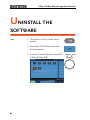
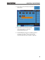
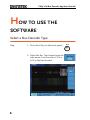
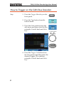
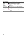
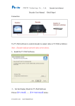
CAN/ LIN Bus Decoder App
GDS 2000A Series
With DS2-8LA or DS2-16LA Module
USER MANUAL
GW INSTEK PART NO.
ISO-9001 CERTIFIED MANUFACTURER
This manual contains proprietary information, which is protected by
copyright. All rights are reserved. No part of this manual may be
photocopied, reproduced or translated to another language without
prior written consent of Good Will Corporation.
The information in this manual was correct at the time of printing.
However, Good Will continues to improve its products and therefore
reserves the right to change the specifications, equipment, and
maintenance procedures at any time without notice.
Good Will Instrument Co., Ltd.
No. 7-1, Jhongsing Rd., Tucheng Dist., New Taipei City 236, Taiwan.
Table of Contents
Table of Contents
INSTALL THE SOFTWARE ................................ 2 UNINSTALL THE SOFTWARE ........................... 4 HOW TO USE THE SOFTWARE ....................... 6 Select a Bus Decoder Type ................................................... 6 How to Trigger on the CAN Bus Decoder ............................. 7 How to Trigger on the LIN Bus Decoder ............................ 11 APPENDIX ...................................................... 15 CAN Bus Decode Display Information: .............................. 15 LIN Bus Decode Display Information: ............................... 15 1
CAN/ LIN Bus Decoder App User Manual
INSTALL THE SOFTWARE
Step
1. Make sure the optional module
“DS2-8LA” or “DS2-16LA” is
installed in the GDS-2000A.
2. Make sure firmware version is
V1.18 or higher.
3. Insert the USB memory stick with
the CAN_LinBus.gz into the USB
port on the front panel.
4. Press the Utility key.
5. Select File Utilities from the bottom
menu.
2
INSTALL THE SOFTWARE
5. Use the Variable knob to select the
USB memory stick and then press
the Select button.
Up
Down
6. Use the Variable knob to select
CAN_ LinBus.gz and then press
the Select button to select it.
Up
Down
7. Press the Select button again to
start installation.
8. The installation is complete when a message
showing “Please turn off the oscilloscope and
turn on again” is displayed.
3
CAN/ LIN Bus Decoder App User Manual
UNINSTALL THE
SOFTWARE
Step
1. Press the Test key on the front
panel
2. Press the APP button from the
bottom menu.
3. Use the Variable knob to select the
CAN Lin Bus APP.
4
UNINSTALL THE SOFTWARE
4. Press the Uninstall button from the
side menu.
5. Press the Uninstall button from
side menu again to start the
uninstallation process.
6. Uninstallation process is complete when a
message showing “Please turn off the
oscilloscope and turn on again” appears.
5
CAN/ LIN Bus Decoder App User Manual
HOW TO USE THE
SOFTWARE
Select a Bus Decoder Type
Step
1. Press the B key on the front panel.
2. Select the Bus Type button from the
side menu. You can select CAN or
LIN as the bus decoder.
6
CAN/ LIN Bus Decoder App User Manual
How to Trigger on the CAN Bus Decoder
Step
1. Press the Trigger Menu key on the
front panel.
2. Press the Type button from the
bottom menu.
3. Press the Others button from the
side menu and then select the Bus
using the Variable knob and Select
key.
4. Press the Trigger On button from
the lower menu and then select the
desired Trigger ON condition
using the Variable knob and Select
key.
7
Up
Down
CAN/ LIN Bus Decoder App User Manual
5. If the Type of Frame option is
selected as the Trigger On
condition, press the Frame Type
button from the lower menu to
select the desired frame type.
6. Select a frame type from the side
menu.
8
HOW TO USE THE SOFTWARE
7. If the Identifier option is selected as
the Trigger On condition, press the
Identifier button from the lower
menu.
8. Select the Format from the side
menu.
9. Press the Identifier button from the
side menu.
10. Enter a binary or hex value with
the Variable knob and Select key.
9
CAN/ LIN Bus Decoder App User Manual
11. Press the Direction button from the
lower menu and select the desired
direction.
12. If Data option is selected as the
Trigger On condition, press the
Data button from the lower menu.
13. Select the desired parameters from
the side menu.
10
HOW TO USE THE SOFTWARE
How to Trigger on the LIN Bus Decoder
Step
1. Press the Trigger Menu key on the
front panel.
2. Press the Type button from the
bottom menu.
3. Press the Others button from the
side menu and then select Bus
using the Variable knob and Select
key.
Up
Down
4. Press the Trigger On button from
the lower menu and then select the
desired Trigger ON condition
using the Variable knob and Select
key.
11
CAN/ LIN Bus Decoder App User Manual
5. If Identifier, Data, Identifier or
Identifier & Data is selected as the
Trigger On condition, press the
Identifier or Data button from the
lower menu.
6. Select the desired parameters from
the corresponding side menu.
12
HOW TO USE THE SOFTWARE
13
CAN/ LIN Bus Decoder App User Manual
7. If the Error option is selected as the
Trigger On condition, select the
desired parameters from the
corresponding side menu.
14
CAN/ LIN Bus Decoder App User Manual
APPENDIX
CAN Bus Decode Display Information:
Field
Description
Start of frame
Start of frame is shown as a white left bracket.
Identifier
The Identifier field is shown as a yellow box.
DLC (data
length control)
The DLC field is shown as a purple box.
Data
The Data field is shown as a cyan box.
CRC
The CRC field is shown as an orange box.
Missing Ack
Missing Acknowledge is shown as a red
exclamation symbol.
End of frame
End of frame is shown as a white right bracket.
Bit stuffing error
Bit stuffing error is shown as a red box.
Error frame and
Overland
Error frame and Overland are shown as a purple
box.
LIN Bus Decode Display Information:
Field
Description
Start of frame
Start of frame is shown as a white left bracket.
Break and Sync
The Break and Sync fields are shown as a purple
box.
Identifier and
Parity
The Identifier and Parity fields are shown a
yellow box.
15
CAN/ LIN Bus Decoder App User Manual
Data
The Data field is shown as a cyan box.
Checksum and
Wakeup
The Checksum and Wakeup fields are shown as
a purple box.
End of frame
End of frame is shown as a white right bracket.
Error type
Error type is shown as a red box.
Sync, Parity,
Checksum
¨
16
When a check sum error happens, the
checksum field turns into an Error type
field.