1
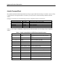
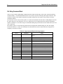
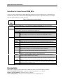
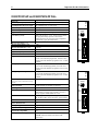
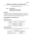
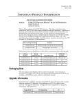
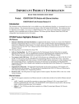
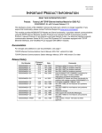
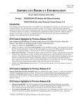
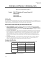
October 27, 1998 GFK-1126U IMPORTANT PRODUCT INFORMATION READ THIS INFORMATION FIRST Product: IC693 CPU Modules with Firmware Release 9.00 IC693CPU351-GP IC693CPU352-DF IC693CPU363-AA (new) Introduction This document contains information that is not available in any other publication; therefore, we recommend you save it for future reference. This document discusses the features of the newly released firmware version 9.00 for current CPU modules IC693CPU351 and IC693CPU352, as well as for the new CPU, IC693CPU363. New Features and Functionality of Firmware Release 9.00 • Software Floating-Point. The CPU351 and CPU363 support all of the floating-point function blocks that are currently supported by the CPU352. They are implemented in firmware using floating point emulation. These Floating-Point math function blocks are described in the IC693 PLC Reference Manual. The CPU352 continues to support Floating-Point math via its built-in math coprocessor. The CPU352 offers a speed advantage over the other two in performing math functions. • User memory totals 240K bytes. %R, %AI, and %AQ references are configurable up to 16K of %R, 8K of %AI and 8K of %AQ memory using the MS-DOS PLC programming software, version 9.02. These three references will be configurable up to 32K in the next release (version 2.2) of the Windows PLC programming software. Configuration instructions for this feature are described in the MS-DOS IC693 Programming Software User’s Manual, and will be included in on-line help in the future release of the Windows PLC Programming Software, version 2.2. • Sequential Event Recorder. A new function block, the Sequential Event Recorder, is available in firmware release 9.00. This function block can be used to record up to 1024 samples of 32 individual discrete (bit) references. This function block is described in the IC693 PLC Reference Manual. Hardware Identification The following table shows the revision level of the circuit boards used in the current versions of these CPUs. CPU Catalog Number IC693CPU351-GP IC693CPU352-DF IC693CPU363-AA Circuit Board ID CV3A2 (Main board) 44A737904-G01R02 or later CA3A2 (Daughter board) 44A737909-G01R01 or later CV3B2 (Main board) 44A737922-G01R02 or later CA3A2 (Daughter board) 44A737909-G01R01 or later CX3A1 (Main board) 44A739579-G01R05 or later ES3A1 (Daughter board) 44A739604-G01R04 or later MS-DOS and Windows are registered trademarks of Microsoft Corporation MSW Circuit Board Version 2 Important Product Information GFK-1126U Firmware Upgrade Kits If you wish to upgrade an existing CPU351 or CPU352 to firmware version 9.00, you may purchase the applicable kit identified in the following table. All previous versions are capable of being upgraded. Firmware 9.00 Upgrade Kit Catalog Number CPU Catalog Number Firmware Upgrade Kit Catalog Number IC693CPU351-(all versions) 44A736935-G11 IC693CPU352-(all versions) 44A739385-G04 IC693CPU363-AA Not applicable. This is a new product. Firmware Identification CPU Catalog Number IC693CPU351-GP IC693CPU352-DF IC693CPU363-AA Motherboard Firmware Version Main: Boot: Main: Boot: Main: Boot: R9.00 (42A1) R9.00 (33A1) R9.00 (42A1) R9.00 (33A1) R9.00 (42A1) R9.00 (33A1) Daughterboard Firmware Version Main: Boot: Main: Boot: Main: Boot: R9.00 (40A1) R1.00 (12A2) R9.00 (40A1) R1.00 (12A2) R9.00 (40A1) R2.00 (30A1) Functional Compatibility • The Windows PLC Programming Software version 2.00 or later must be used to take advantage of C programming or Sequential Function Chart (SFC) subroutines. • Version 4.00 of the C toolkit must be used for C programming. • The MS-DOS PLC Programming Software Version 9.02 or later must be used to take advantage of the new features introduced in firmware release 9.00. These new features are listed in the section “New Features and Functionality of Firmware Release 9.00.” Note that the CPU363 can be configured with the MS-DOS PLC Programming Software Version 9.01, but only features prior to firmware release 9.00 are supported in that software version. Operating Notes User Flash Contents User information, consisting of program, configuration, CPU ID (used for SNP communications), and status tables in RAM memory, will automatically be cleared if the CPU firmware in flash memory is changed. So you will need to restore these if upgrading firmware. A recommended procedure is to first back up your user information from RAM memory to Flash memory. Then write your new firmware to Flash memory (firmware is stored in a different location in Flash memory than that used for storing user information such as program, configuration, etc.). Finally, write your user information back out of Flash into RAM memory. As an alternative, your user information (program, configuration, etc.) can be restored from a computer-based backup program folder using your PLC programming software. The SNP ID must be set separately, using the programming software or the Hand-Held Programmer (HHP). Important Product Information 3 GFK-1126U Firmware Upgrade Procedure Note: The Model 35x and 36x CPU operating firmware is stored in FLASH memory. The firmware upgrade is provided on a floppy disk and must be serially downloaded from a Personal Computer. An IBM AT personal computer or better PC with a minimum 640K of RAM, one 3.5” floppy drive, MS-DOS version 3.3 or later (or Windows 95 or later), a hard drive, and one RS-232 serial port is required. In addition, a serial cable is required. The following serial cable kit is available from GE Fanuc: IC690ACC901 Mini Converter Kit with cable (RS-232/RS-485) Optionally, the cable can be assembled from the following parts: IC690ACC900 RS-232 to RS-485/422 Converter Unit IC693CBL303 15 Pin RS-485 Serial Cable IC690CBL705 25 Pin RS-232 Serial Cable * IC690CBL702 9 Pin RS-232 Serial Cable * * Only one of these cables is required. Selection depends on PC Serial Port Connector. Changing Firmware to an Earlier Version If you have a CPU351 or CPU352 with firmware version 9.00, and you desire to install a pre-9.00 version of firmware, then a special upgrade disk must be obtained from GE Fanuc. Do not attempt to use a firmware version 8.10 or earlier upgrade disk on a CPU that contains firmware version 9.00. Note that pre-9.00 firmware versions do not support the CPU363. Option Module Revision Requirements • Ethernet Interface Module Compatibility. All IC693 Ethernet Interface (IC693CMM321) modules used with these CPUs should be updated to IC693CMM321 firmware release 1.10 or later. This is also a requirement of the TCP/IP Ethernet version of the MS-DOS programming software. During a Run Mode Store (Alt + S hot key combination) of a large program block (greater than 14 kilobytes), the Ethernet module may time out, causing communications to fail. Changing the Communications Window to Run-to-Completion mode, or storing the program in Stop mode, will allow the store to take place successfully. • FBC Compatibility. FBC version 3 or later is required for these CPUs. • GCM Compatibility. Fab board R08 or later of the IC693CMM301 should be used with the CPU352. Writing Flash Using a Serial Programmer When writing very large programs to flash memory, it may be necessary to increase the Windows PLC programming software request timeout value to avoid receiving a request timeout message. An upper bound of 25 seconds is typically satisfactory Problems Resolved in Firmware Version 9.00 Keyswitch Configured as RUN/STOP Switch Previously, when the keyswitch was configured as a RUN/STOP switch, moving the keyswitch to the STOP position would not affect the current PLC state if the PLC was already in either STOP NO/IO or STOP IO SCAN mode. In firmware version 9.00, the keyswitch will now change the PLC to STOP IO SCAN or STOP NO/IO based on the configured value, even if the PLC is already in a “STOP” mode. Storing IC693CMM321 Configuration with Windows PLC Programming Software Issue It was possible to get a watchdog time-out failure when storing an IC693CMM321 configuration with the Windows PLC Programming software, Version 2.1 or earlier. This problem has been corrected in firmware version 9.00. RET_PBLOCK_LIST The RET_PBLOCK_LIST service request would only function correctly with 24 or less subroutines in the program in firmware version 8.00. The request now functions correctly with any number of subroutines in version 9.00. 4 Important Product Information GFK-1126U Service Request #7 SVC REQ #7 would allow ladder logic to set certain illegal dates such as 2/29/01. Illegal dates are no longer allowed to be entered by the user program. Changes to Documentation The IC69* PLC Serial Communications User’s Manual will be updated to describe the Generic Output and pager enunciation feature in its next revision (rev D). These features are supported by the CPU351, CPU352, and CPU363 CPUs’ embedded serial ports. Sending a COMM_REQ to the CPU351, CPU352, or CPU363 serial ports. When sending a Communications Request (COMM_REQ) to the CPU351, CPU352, or CPU363 serial ports, the SYSID of the COMM_REQ must be 1 and the TASK ID must be 19 decimal for port 1 or 20 decimal for port 2. RTU With the above exception about the SYSID and TASK ID fields, using RTU on the CPU351, CPU352, or CPU363 serial ports is the same as using RTU on a CCM, which is described in the IC69* PLC Serial Communications User’s Manual. Generic Output Generic Output is selected for Port 1 or Port 2 of the CPU351, CPU352, or CPU363 CPUs by choosing “CUSTOM” as the mode for the port in the CPU Configuration and storing this to the PLC. Generic Output is accomplished by using the put string COMM_REQ. Using the autodial COMM_REQ with the put string COMM_REQ accomplishes the pager enunciation feature as described below. Using Pager Enunciation and Generic Output This feature allows the CPU351, CPU352, and CPU363 CPUs to automatically dial a pager via modem and send a specified byte string from Serial Port 1 or 2. Pager dialing and message transmission are set up by COMM_REQ functions in the ladder logic. Note To implement this feature, Serial Port 2 must be configured as a CUSTOM port as mentioned above in the “Generic Output” item. Pager enunciation is implemented by three commands, requiring three COMM_REQ command blocks: Autodial: 04400 (1130H) -Dials the modem. This command works the same way that the SNP Master Autodial command 7400 does. Put string: 04401 (1131H) - Specifies an ASCII string, from 1 to 250 bytes in length, to send from the serial port. Autodial: 04400 (1130H) - It is the responsibility of the PLC application program to hang up the phone connection. This is accomplished by reissuing the autodial command and sending the hang-up command string. Important Product Information 5 GFK-1126U Autodial Command Block The Autodial command automatically transmits an Escape sequence that follows the Hayes convention. If you are using a modem that does not support the Hayes convention, you may be able to use the Put String command to dial the modem. Examples of commonly used command strings for Hayes-compatible modems are listed below: Command String Length ATDP15035559999<CR> ATDT15035559999<CR> ATDT9,15035559999<CR> ATH0<CR> ATZ <CR> 16 (10H) 16 (10H) 18 (10H) 5 (05H) 4 (04H) Function Pulse dial the number 1-503-555-9999 Tone dial the number 1-503-555-9999 Tone dial using outside line with pause Hang up the phone Restore modem configuration to internally saved values Table 6-1 lists a sample COMM_REQ command block that dials the number 234-5678 using a Hayes-compatible modem. Table 6-1. Sample Command Block for CUSTOM Protocol Autodial Command Word Definition Values 1 0009H CUSTOM data block length (includes command string) 2 0000H NOWAIT mode 3 0008H Status word memory type (%R) 4 0000H Status word address minus 1 (Register 1) 5 0000H not used 6 0000H not used 7 04400 command (1130H) Autodial command number 8 00030 (0001H) Modem response timeout (30 seconds) 9 0012 (000CH) Number of bytes in command string 10 5441H A (41H), T (54H) 11 5444H D (44H), T (54H) 12 3332H Phone number: 13 3534H 4 (34H), 5 (35H) 14 3736H 6 (36H), 7 (37H) 15 0D38H 8 (38H) <CR> (0DH) 2 (32H), 3 (33H) 6 Important Product Information GFK-1126U Put String Command Block Table 6-2 lists a sample COMM_REQ command block that sends the data string, “hello world” using the Put String command (04401). A maximum transmit timeout of 30 seconds is specified. The string data begins at Word 10. This command is similar to the Autodial command except that Put String does not send the escape sequence for Hayescompatible modems. The Maximum Transmit Timeout field specifies, in seconds, the maximum time interval the COMM_REQ will wait for the entire string to be sent. If this time is set to 0, a default value of 4 seconds plus the time required to transmit the number of characters is used. If the string is not transmitted during the specified interval or the default interval, an error code is generated. The Number of Bytes in Command String field specifies the length of the command string to be sent. This length includes all characters. A status code indicating successful transmission will be returned when the string has been completely sent out the serial port. Table 6-2. Sample Command Block for Put String Command Word Definition Values 1 0009H CUSTOM data block length (includes command string) 2 0000H NOWAIT mode 3 0008H Status word memory type (%R) 4 0000H Status word address minus 1 (Register 1) 5 0000H not used 6 0000H not used 7 04401 command (1131H) Put String command number 8 001EH Maximum transmit timeout (30 seconds) 9 000BH Number of bytes in command string 10 6568H h (68H), e (65H) 11 6C6CH l (6CH), l (6CH) 12 206FH o (6F), “ “ (20H) 13 6F77H w (77H), o (6FH) 14 6C72H r (72H), l (6CH) 15 0064H d (64H) Important Product Information 7 GFK-1126U Status Word for Custom Protocol COMM_REQs A value of 1 will be returned in the COMM_REQ status word upon successful completion of a CUSTOM protocol command. Any other value returned in the COMM_REQ status word is an error code where the low byte is a major error code and the high byte is a minor error code. Table 6-3. Status Codes for Custom Protocol Major Status Code Description 1 (01H) 12 (0CH) Successful Completion (this is the expected completion value in the COMM_REQ status word). Local CSTM_PROT error — Port configuration command 65520 (FFF0H). An error occurred while processing a local command. The minor error code identifies the specific error. COMM_REQ command is not supported. 2 (02H) Remote CSTM_PROT error — Put String command 4401 (1131H). An error occurred while processing a remote command. The minor error code identifies the specific error. String length exceeds end of reference memory type. 2 (02H) COMM_REQ data block length is too small. String data is missing or incomplete. 3 (03H) Serial output timeout. The serial port was unable to transmit the string. (Could be due to 48 (30H) missing CTS signal when the serial port is configured to use hardware flow control.) COMM_REQ timeout. The COMM_REQ did not complete within a 20-second time limit. 50 (32h) Autodial Error — Autodial command 4400 (1130). An error occurred while attempting to send a command string to an attached external modem. The minor error code identifies the specific error. Not used. 1 (01H) The modem command string length exceeds end of reference memory type. 2 (02H) COMM_REQ Data Block Length is too small. Output command string data is missing or 3 (03H) incomplete. Serial output timeout. The serial port was unable to transmit the modem autodial output. (May 4 (04H) be due to missing CTS signal when the serial port is configured to use hardware flow control.) Response was not received from modem. Check modem and cable. 5 (05H) Modem responded with BUSY. Modem is unable to complete the requested connection. The 6 (06H) remote modem is already in use; retry the connection request at a later time. Modem responded with NO CARRIER. Modem is unable to complete the requested 7 (07H) connection. Check the local and remote modems and the telephone line. Modem responded with NO DIALTONE. Modem is unable to complete the requested 8 (08H) connection. Check the modem connections and the telephone line. Modem responded with ERROR. Modem is unable to complete the requested command. 9 (09H) Check the modem command string and modem. Modem responded with RING, indicating that the modem is being called by another modem. 10 (0AH) Modem is unable to complete the requested command. Retry the modem command at a later time. An unknown response was received from the modem. Modem is unable to complete the 11 (0BH) requested command. Check the modem command string and modem. The modem response is expected to be either CONNECT or OK. COMM_REQ timeout. The COMM_REQ did not complete within a 20-second time limit. 50 (32H) 13 (0DH) 14 (0EH) Documentation Instructions for using these three modules can be found in the latest version of the following manuals: General Configuration Instructions: IC693 PLC Programming Software User’s Manual Ladder Logic Programming: IC693 PLC Reference Manual Serial Communications: IC69* PLC Serial Communications User’s Manual, Rev. D 8 Important Product Information GFK-1126U IC693CPU351-GP and IC693CPU352-DF Data CPU Type Total Baseplates per System Single slot CPU module 8 (CPU baseplate + 7 expansion and/or remote) Load Required from Power Supply 890 milliamps from +5 VDC supply Processor Speed 25 MegaHertz Processor Type 80386EX Typical Scan Rate .22 milliseconds per 1K of logic (Boolean contacts) User Memory (total) 240K (245,760) Bytes. Note: Actual size of available user program memory depends on the amounts configured for the %R, %AI, and %AQ configurable word memory types (described below). Discrete Input Points - %I Discrete Output Points - %Q 2,048 2,048 Discrete Global Memory - %G 1,280 bits Internal Coils - %M 4,096 bits Output (Temporary) Coils - %T 256 bits System Status References - %S 128 bits (%S, %SA, %SB, %SC - 32 bits each) Register Memory - %R Configurable in 128 word increments, from 128 to 16,384 words with DOS programmer, and from 128 to 32,640 words with Windows programmer Ver. 2.2 when available. Analog Inputs - %AI Configurable in 128 word increments, from 128 to 8,192 words with DOS programmer, and from 128 to 32,640 words with Windows programmer Ver 2.2 when available. Analog Outputs - %AQ Configurable in 128 word increments, from 128 to 8,192 words with DOS programmer, and from 128 to 32,640 words with Windows programmer Ver. 2.2 when available. System Registers (for reference table 28 words (%SR) CPU 351 ON/RUN OFF/ STOP PORT 1 RS-232 PORT 2 RS-485 CPU 352 viewing only; cannot be referenced in user logic program) ON/RUN Timers/Counters >2,000 (depends on available user memory) Shift Registers Yes Built-in Serial Ports 3 (one uses connector on PLC power supply). Supports SNP, SNPX (on all three ports) and RTU (on Ports 1 and 2). Requires CMM module for CCM. Communications LAN – Supports multidrop. Also supports Ethernet, FIP, Profibus, GBC, GCM, and GCM+ option modules. Override Yes Battery Backed Clock Yes Interrupt Support Supports the periodic subroutine feature. Type of Memory Storage RAM and Flash PCM/CCM Compatibility Yes Floating Point Math Support CPU351: Firmware-based CPU352: Hardware-based (uses built-in math coprocessor) SNP P1 P2 OFF/ STOP PORT 1 RS-232 PORT 2 RS-485 SNP P1 P2 Important Product Information 9 GFK-1126U IC693CPU363-AA Data a47500 CPU Type Total Baseplates per System Single slot CPU module 8 (CPU baseplate + 7 expansion and/or remote) P1 Load Required from Power Supply 890 milliamps from +5 VDC supply P2 Processor Speed 25 MegaHertz Processor Type 80386EX Typical Scan Rate .22 milliseconds per 1K of logic (Boolean contacts) User Memory (total) 240K (245,760) Bytes. Note: Actual size of available user program memory depends on the amounts configured for the %R, %AI, and %AQ configurable word memory types (described below). Discrete Input Points - %I Discrete Output Points - %Q 2,048 2,048 Discrete Global Memory - %G 1,280 bits Internal Coils - %M 4,096 bits Output (Temporary) Coils - %T 256 bits System Status References - %S 128 bits (%S, %SA, %SB, %SC - 32 bits each) Register Memory - %R Configurable in 128 word increments, from 128 to 16,384 words with DOS programmer, and from 128 to 32,640 words with Windows programmer Ver. 2.2 when available. PS PORT CPU 363 ON OFF Analog Inputs - %AI Configurable in 128 word increments, from 128 to 8,192 words with DOS programmer, and from 128 to 32,640 words with Windows programmer Ver 2.2 when available. Analog Outputs - %AQ Configurable in 128 word increments, from 128 to 8,192 words with DOS programmer, and from 128 to 32,640 words with Windows programmer Ver. 2.2 when available. System Registers (for reference table 28 words (%SR) viewing only; cannot be referenced in user logic program) Timers/Counters >2,000 (depends on available user memory) Shift Registers Yes Built-in Serial Ports 3 (one uses connector on PLC power supply). Supports SNP, SNPX (on all three ports) and RTU (on Ports 1 and 2). Requires CMM module for CCM. Communications LAN – Supports multidrop. Also supports Ethernet, FIP, Profibus, GBC, GCM, and GCM+ option modules. Override Yes Battery Backed Clock Yes Interrupt Support Supports the periodic subroutine feature. Type of Memory Storage RAM and Flash PCM/CCM Compatibility Yes Floating Point Math Support Yes, firmware-based PORT 1 RS-232 PORT 2 RS-485 FRAME