1
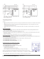
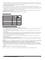
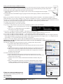
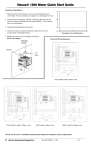
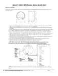
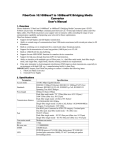
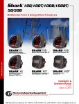
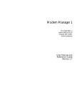
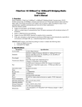
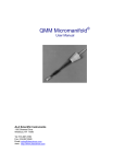
Quick Start Guide for DMMS 300/350/425 Meters
Hardware Installation
Meter Dimensions and Cut-out
Electrical Installation
(NOTE: This guide shows some possible wiring configurations. Refer to the meter’s manual for additional configurations.)
Three-Phase, Four-Wire Wye with Direct
Voltage and CTs
e Electro Industries/GaugeTech
Three-Phase, Four-Wire System Wye with
CTs and PTs
Doc# E104777
Q-1
Three-Phase, Three-Wire System Delta with
Direct Voltage and CTs
Three-Phase, Three-Wire Open Delta with
two CTs and two PTs
Programming the Meter
NOTES:
• Basic programming information is given here. For step-by-step instructions refer to the meter’s User manual, on the enclosed
CD.
• Programming tasks are divided into 9 Groups that contain programming Functions. Use the meter buttons to access the
Groups/Functions and program the meter.
• Programmable Function values are always four-digit numeric fields. For example, to enter the number 25, you must enter
0025.
Enter Programming Mode:
1. Press and hold PHASE/NEXT and then press AMPS/THD. Release PHASE/NEXT and keep holding AMPS/THD until 3
appears in the middle display.
2. Release AMPS/THD and press PHASE/NEXT to multiply the 3 to 333.
3. Digits begin scrolling in the upper display. Press PHASE/NEXT each time 5 appears, until the middle display reads 555 (this
is the meter’s password).
4. 0 appears in the upper display, indicating that the meter is now in programming mode for Group 0.
Exit Programming Mode: IMPORTANT! You MUST exit Programming Mode to store any changes.
NOTE: The steps to exit Programming Mode depend on your current stage. If you are located at Function level begin at Step 1; if
you are located at Group level, begin at Step 3.
1. Press MAX/MIN/LIMITS until the Group number in the upper display is followed by E (Exit).
2. Press AMPS/THD to return to Group level.
3. Press MAX/MIN/LIMITS until E appears in the upper display.
4. Press AMPS/THD to exit Programming Mode.
Programming Voltage, Amp, and Watt Full Scale Settings
NOTE: Refer to PT and CT tables on page 3.
1. Enter programming mode (see instructions above).
2. Press MAX/MIN/LIMITS until 1 appears in the upper display.
3. Press AMPS/THD to activate GROUP 1:
- 10 appears in the upper display
- the middle display indicates Scale Factor setting
- the lower display shows the Full Scale voltage setting. See the figure on the right.
NOTE: To set Full Scales for Amps and Watts, follow the same procedure, but in step 3, press
MAX/MIN/LIMITS until either 11 is displayed - for Amps settings, or 12 is displayed - for Watts settings.
4. Press AMPS/THD to begin data entry; the lower display is replaced with a single vertical line.
e Electro Industries/GaugeTech
Doc# E104777
Q-2
5. Press VOLTS/THD to move the vertical line UP or DOWN to set the Scale Factor: UP represents Kilovolts; DOWN represents
Volts. (NOTE: If you are setting Amps Full Scales, UP represnts Kiloamps, and DOWN represents Amps; if you are setting Watts
Full Scales, UP represents Megawatts and DOWN represents Kilowatts.)
6. Press AMPS/THD to store the value.
7. To select Decimal placement, press VOLTS/THD to move the decimal point, then press AMPS/THD to store the setting.
8. The middle display contains the present Full Scale for Volts; four dashes appear in the lower display for entering a new Full Scale
setting. Enter the four digit Full Scale value you want by pressing VOLTS /THD to increase the digit’s value, and then pressing
AMPS/THD to store each digit. Repeat until the desired value is entered.
9. The lower display contains the new Full Scale setting; the middle display indicates the Scale Factor; the Group and Function
number appear in the upper display.
IMPORTANT! When you are done, follow the Exiting procedure on page 2.
Common PT and CT Values
SECONDARY PT VALUES
PT RATIO
FULL
SCALE
75 V (Suffix 75) L-N MAX
120:1
9.00 KV
120/208 V
1:1 (Direct)
120.0
120/208 V
4:1
0480 V
120/208 V
120:1
014.4 KV
277/480 V (Suffix G)
1:1 (Direct)
0300 V
120/208V
600:1
072.0 KV
120/208
1150:1
138.0 KV
Programming the Meter Address and Baud Rate
1. Enter Programming Mode (follow instructions on page 2).
2. Press AMS/THD to access Group 0, Function 0 (the upper display reads 0.0).
3. Press MAX/MIN/LIMITS to access Group 0, Function 1 (the upper display reads 0.1). This is the setting for the meter’s address.
The current setting is shown in the bottom display.
4. Press AMPS/THD to change the meter’s address. The current address is now in the middle display, and 4 dashes are in the
bottom display.
5. Press VOLTS/THD to begin entering the first digit of the new meter address. Remember to use leading zeros - the address must
be a 4 digit number. As you press VOLTS/THD the leftmost dash in the bottom display scrolls from 0 to 9. When the digit you
want is shown, press AMPS/THD to select it and move to the next digit.
6. Repeat step 5 until all 4 digits have been entered. The upper display will again show 0.1 and the new meter address will be
in the bottom display.
7. Press MAX/MIN/LIMITS to access Group 0, Function 2 (the upper display reads 0.2). This is the setting for the meter’s Baud
Rate. The current setting is shown in the bottom display.
8. Press AMPS/THD to change the Baud Rate. The current Baud Rate is now in the middle display, and 4 dashes are in the bottom
display.
IMPORTANT! The meter’s Baud Rate must match that of any device with which it is communicating. Valid Baud Rates are
1200, 2400, 4800 and 9600. The DMMS 350 meter’s Ethernet Module has a default Baud Rate of 9600.
9. Press VOLTS/THD to begin entering the first digit of the new Baud Rate. As you press VOLTS/THD the leftmost dash in the
bottom display scrolls from 0 to 9. When the digit you want is shown, press AMPS/THD to select it and move to the next digit.
10. Repeat step 5 until all 4 digits have been entered. The upper display will show 0.2 and the new Baud Rate will be in the bottom
display.
IMPORTANT! When you are done, follow the Exiting procedure on page 2.
NOTE: Refer to your meter’s User manual on the enclosed CD for additional step-by-step programming instructions.
e Electro Industries/GaugeTech
Doc# E104777
Q-3
Setting up the Ethernet Option (DMMS 350 Meter)
The Ethernet module for the DMMS350 allows you to access the meter directly from any computer on the Local Area
Network (LAN). The module is connected to the back of the meter. It has an RJ45 Ethernet port and 4 Status LEDs.
See the figure on the right. To physically connect the meter and your PC:
1. Connect the Ethernet port directly to a computer with a crossover cable or through a hub with a straight Status LEDs
Ethernet cable.
2. The link light (LK) on the EPM5350 (upper right green LED) should light up when the connection has been
established.
RJ45 Port
Before you can connect to the network, you must configure the Ethernet module’s IP address. The IP address should be one
greater than the PC you are using to configure it (e.g., if the PC’s IP address is 192.168.1.5, set the Ethernet module’s IP address to
192.168.1.6). You can find your PC’s IP address through the Start Menu: open Control Panel and then Network connections. Click on
your Ethernet connection and then the Support tab to see your IP address, default gateway, and subnet mask.
To configure the IP address for the Ethernet module:
1. Click Start>Run and type “cmd” in the entry field.
2. Type “arp -a” and press Enter. You will see a list of IP addresses. If there is only one IP address:
a. Type “arp -s 0.0.0.0. 00-00-00-00-00-00“ to set up a generic IP address that you can configure for the Ethernet
module.
b. Type “arp -a” to confirm that the generic IP address is
now listed. See the figure on the right.
3. Type “arp -s <IP address for Ethernet Module> <Mac address of Ethernet Module>.
NOTE: The Mac address is printed on the side label of the Ethernet module. It has the format xx-xx-xx-xx-xx.
4. Type “telnet <IP address for Ethernet Module> 1”: this connection will fail within a few seconds.
5. Type “telnet <IP address for Ethernet Module> 9999”: and press Enter to access Setup Mode. You can now configure parameters
for the Ethernet Module by entering one of the numbers on the Change Setup Menu (for example, enter “1” to configure Network
or IP settings), or you can confirm the default values by pressing Enter.
6. Enter “S” to save any changes you have made. The Ethernet Interface will perform a power reset.
IMPORTANT! The Ethernet module and the meter must be set to the same Baud Rate. The default Baud Rate for the
Ethernet module is 9600.
You must also configure the LAN connection for your PC or laptop. Follow this procedure:
a. Click Start>Control Panel>Network connections.
b. Right click on the LAN connection you will be using for the meter. See the screen on
the right.
c. Highlight Internet Protocol (TCP/IP) and click Properties (see second screen on right).
d. Click “Use the Following IP Addess and enter the IP address and subnet mask for
your network (your network administrator should be able to supply this if needed (see
the third screen on the right).
To connect to the meter from your PC:
a. Install Communicator EXT software (located on the enclosed CD) on your PC.
b. Open Communicator EXT and click the Connect icon in the Title bar. You will see the
Connect screen, shown below.
c. Enter the meter’s Device address and the Ethernet Module’s IP address and press
Connect.
d. Once you are connected to the meter, you can use Communicator EXT to configure
settings. Click Help>Contents from the Title bar to open the Communicator EXT
User Manual online and view setup instructions.
G Electro Industries/GaugeTech
1800 Shames Drive Westbury, New York 11590
Tel: 516-334-0870
FAX: 516-338-4741
www.electroind.com
e Electro Industries/GaugeTech
Doc# E104777
E104777 V.1.01 041510
Q-4