1
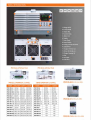
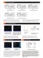
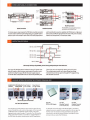
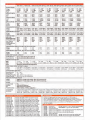
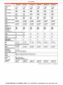
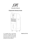
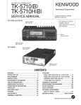
Doc. IA-0014
VP ELECTRONIQUE - 91746 MASSY CEDEX - Tel: 01.69.20.08.69 - [email protected] - www.vpelec.com
Powerful Stretch with Multi-range Technology
The FEW-Series is a single-output multi-range programmable switching DE Power Supply covering a power range
up to IEISIIW. This series of products include fifteen models with the combination of 3l]‘v’, SEW‘, 'lEEl"r.i", 25l]"v" and SfiEr"v'
rated voltages and 3ErEl‘-iv’. FEUW and '|lIiSfl‘w maximum output powers. The multi-range feature allows the Flexible
and efficient configuration ofvoltage and current within the rated power range. J-‘ts the PSW-Series can be
connected in series for maximum 2 units or in parallel for maximum 3 units, the capability ofconnecting multiple
FEW-Series units for higher voltage or higher current output provides a broad coverage of applications. with the
Flexibility of multi-range power utilisation and seriesfparallel connection, the PSW-Series significantly reduces the
users‘ cost for various power supply products to accommodate the projects with dilferent power requirements.
The c.v,rc.c priority selection of the PSW-Series is a very useful feature for Dl..lT protection. The conventional
power supply normally operates under C.‘v' mode when the power output is turned on. This could bring a high
inru sh current to the capacitive load or curren t-inte nsive load at the power out pu t-on stage. Taking the l-"v’ curve
verification of LED as an example, it becomes a very challenging taslt to perform this measurement using a
conventional power supply. ‘wlith LED connected to a power supply under E."v' mode as the initial setting, when
the power output is turned on and the voltage rises to the LED forward voltage, the current will suddenly pealt up
and exceed the preset value of current Ii mit. Ll pen detecting this high cu rre nt, the power supply starts the
transition from C.‘v' mode to CE mode. Though the current becomes stable after the CL mode being activated,
the current spilte occurred at the t'j.v and i'.'I.E crossover point may possibly damage the DLIT. At the power
output-on stage, the PSW-Series is able to operate under I'I.E priority to limit the current spike occurred at the
threshold voltage and therefore protects DLJT from the inrush current damage.
The adjustable slew rate of the PSW-Series allows users to set for either output voltage or output cu rren t,
a specific rise time from low to high level transition, and a specific fall time from high to low level transition.
This facilitates the characteristic verification of a DLIT during voltage or current level changes with controllable
slew rates. lvlost manufacturing tests of lighting device or large capacitor during power output-on are associated
with the occurrence of high surge current, which can greatly reduce the life time of the DLIT. To prevent inrush
current from damaging current-intensive devices, a smooth and slow voltage transition during power Dn-Dff can
significantly reduce the spilte current and protect the device from high current damage.
The ova and DEF‘ are provided with the F'S‘w'-Series. Both ova and DEF levels can be selected, with default
level set at llifiti, of the rated voltageylcurrent of the power supply. When any ofthe protection levels is tripped,
the power output will be switched oFF to protect the DUT. The PSW-Series provides USE Host; Device and LAN
interfaces as standard and GPIE~LlSB adaptor as optional. The Lab‘v'iew driver and the Data Logging PE software
are supported on all the available interfaces. An analog controlfmonitoring connector is also available on the
rear panel for external control of power Dn,l'Dlf and er-rternal monitoring of power output ‘voltage and Current.
PSW-Series {H"v'] Hear Panel
PSW-Series |:L"v'] Hear Panel
—
-
it
—J
Ii.-me-;i -_-no ol|.|rIoIl-|I|.1I|:I||.u-r-rl
—
l§i:,'I'
"
‘
-I--tr;
cl.‘-.
W
il-
.___.-
l.I|.I|io|g|.1.I'II-I.Ili;:I||:Il-rI|.tI.I--.1.-In-I
‘I
I
’
ctr
rt‘.-Ii
I-
PARALLEL oasaarion rs units}
MDDEL
SIHSLEIJHIT IUHITS
struts oetaarion r 2 UNITS 1
3-li..ll'IIITS
esw so-:2
esw so-toe
' Psw so-1s.s
FEW‘ SD-I?
:.cv,n:xr.a
zowrarr. tinvyiex ainvpisx
aovhoaa Ixnvoiex 3'lIl‘v'ffl1-1.15.
tovhxsa Isovnra so-r,uo.sa
Bovyara Psovysta aovpnx
FSW SI}-Ill-.5
tfiv',r-|o.5it
tov,'ui.sa
_ FEW‘ so-r.o.s
PSW ‘I-E-III-‘LI
itovntrt '|ErIJv,r14.4i!t 1r.nvrh.et
1tov,rit.e. isnv,os.sx irovreat
iozrvraisa na:rv,r-eta ionv,rt-xta
FEW 'l-E-II-I-".2
FEW 3D-35
FEW SD-H
FEW SD-‘IDS
FSW SD-13.5
FEW I-IEIIII-*'l-ll--iI
PSW I-Sill-Tl .5
FEW “.I5lIl-4.5
PSW I51!-'5‘
sovyssa
zsovytsw
zsovyaa
sovyrzw
sovytia
zsovysit
25'EI‘t'_|FlS.|t
FEW 3D-I-IE
'-
I
FEW SD-2?
FEW 1'5-II-14.4
J
II
I
_|--in
-I
FSW 'l'E-III-'I'l .-E
I5[|"i|'|I'l§l-.5-.|!I.
' |=sixr:so-i.s
I5[|"r'|I'E FA
'|=swaso-e
FEW 25'I'.l-13-.5
PSW Sflll-2.S-E
PSW SIIIII-1.32
tcow-|.3:u. stov,rt.s-in
PSW SIlIl.'l-1.3-I
FEW E-III-I.-I-I
F”
I
.tstrvhs.sx tsorpra tsnvrazes
a::ovh,.ux toovnssa wor,rr.:o.=.
taovratsa soovmsa tuor,r.t.t-is
FEW El]-13.5
P5‘-If 3'3‘-4'3-5 """“""'-“'"*"'-*"“- '““““*'
FEW EDD-I.iH
PSW SIII-I.S-S
EIIliT'i',flI.'EIEil|.
‘I-
-|-L-_
t
sovpaa
sovpaa
sovrm.
sovnotn
SCI-'-.I',i"|1.5a
sovrrat
sovnizisa
1stiv,n1.sx
sovytra
aov,r-u1s.=r.
1sov,r2:ra
io:iv,rr.:rl
istiv,rir...ir.
1o:iv,er.sx
sa:iv,rr.tr-.
3IlJ'iI',I"l4.-iei
sa:iv,r:r1.sx
rv,rn
iv,rn
iv,rn
rv,rn
nra
nrx
H,r.n.
ura
n,rx
r~i,rx
iv,rn
n,rn
'lEEl'Ir',I'4=[ll.5Fl
"iiia:="l
FEW El]- 1}' go-sov, o- tr:-. rsov.-1
-—-rl-—--I
|
.__- .-.
Ex
PSW HEI- 13.5 l'3'-15'3"-i 1}-13.5%., 3-E'II".i.'|
12
24
36
72
‘I08
4.5
9.0
135
27
40.5
r
I-
225 4.5 6.75 7.2
l
_
_
7!”
II
_
3
—rr@'
\
*--...____--- Type lll
'I-...,_____'
10
I‘
_
Wit-199V)
BU
V)
I-r
~"'-..,,__ —-— Type Ill
88
S8
~‘"h_,
20
"-
l
180
160
i Tyne II
\\
‘
WIEQBVJ
N
i Typel
Y
Inn‘
26.6
14.4
21.6
'.
'
I
I
' —i,\"<t
is
l
.
160
___ Type iii
~‘"n
r__
Vdtage
—v=@-
i Type ll
I I ..,,,
vq""'---.._,, I
U1$
11-1
= v1&‘61‘8§8t3i
Q.
8-
8_
a
8-
0
E
gl--u
I
5
O
I
10
zoo
1'
'-. _
,__
E0150
V0
Y.
‘Q
I
P_o.._-
Q
-
Q‘
IED
:
Q
I
W
q\.-i-
45
CD
01..
I-D
o
i-» ,,_
l .
G
8
81
PSW 160V Series Operating Area
5@
_
!
iasow
‘Q ‘
‘U0
l
Ii?2OW
s_“
0
4
2(1)
QQQQ
iosow
0 .0
_
I
-...
100
1'4
——"
0
_- L’.-
5-.-
3..
CU rre nt(A)
I
——‘l_
TDD
> 300
Q‘-'0
u_,_or-:1
.
CD
2
I'
'
800
a-~
pupae 1D8fl'W
.
."u.'
0
_
lime '
2
3-».
I
9(1)
.4 ’-
_I
35
PSW 80V Series Operating Area
if
'
I
30
25
Cu r|'er|t( A)
PSW 30V Series Operating Area
350
I
20
15
Current(A)
088889‘
0
I
l
1
2
l
3
4
5
Cu rren! (A)
PSW 250V Series Operating Area
PSW 800V Series Operating Area
When the power supply is configured that the total output (Current x
Voltage output) is less than the rated power output, it functions as a
typical Constant Current (C.C) and Constant Voltage (C.V) power supply.
However, when the power supply is configured such that the total output
power (Current x Voltage Output) exceeds the rated power output, the
effective output is actually limited to the operation area ofthe unit.
_
I
I
8
DSO
I
GDS- 3354
L
'
.
I
LED Load
. (AR111)
1, -—-—-----—-Q
The lnrush Current and Surge
Voltage occur at LED Forward
Voltage(Vf)Under C.V Priority
The CC Priority Feature Effectively Limits
the Occurrence of lnrush Current and
Surge Voltage when the Supplied Voltage
Rises to the LED Forward Voltage
The PSW-Series provides C.C Mode and C.V Mode to fit various
applications in the general purpose market. To get into critical
application niches, however, the power supply needs to provide
-‘C
"'<
unnm
V-I Characteristic
of Diode
advanced features to meet the specific requirements. The C.C
and C.V Priority Selection enable the power supply to run under
C.C priority, rather than normal CV priority, at the output-on stage.
PSW
The Adjustable Rise Time
ofthe PSW 30V
The Adjustable Rise Time
of the PSW 800V
The PSW-Series has adjustable slew rates for the level transition of both
Current and Voltage. This gives the PSW-Series power supply the ability
to set specific rise time and fall time ofthe Voltage and Current drawn
from the power supply to verify DUT performance during the Voltage /
Current level transition. The feature also provides the benefit to slow
down the voltage transition at the power output-on to protect DUT from
inrush current damage. This is especially useful for the test of heavycurrent-drawn devices like capacitors.
Operation Under C.V Priority and
C.C Priority Respectively
Bléed
resistor
Load
PSW-Series Built-in Bleed Resistor
The PSW-Series employs a bleed resistor in parallel with the output
terminal. Bleed resistor is designed to dissipatch the power from the
power supply filter capacitors when power is turned off and the load is
disconnected. Without a bleed resistor, power terminal may remain
charged on the filter capacitors for some time and be potentially
hazardous. In addition, bleed resistor also allows for smoother voltage
regulation ofthe power supply as the bleed resistor acts as a minimum
voltage load. The bleed resistance can be turned on or off using the
configuration setting.
Master
unit
l@"°
l
WI
-I -
‘fie
—l_\
iv ii“
llll ‘“
L :ql
I Ii
1-?
s +s
€l)
I"
Egi _, .3
Master unit
,
_
.
5
,
(B
Slave
,!l"fiEEil:l"'
i I
“““‘
I.,3
Slave unit
l
77 ‘ti +8
‘
"
"ii" 1* iriitag1_si
L0,,Slave -ss::,
,
vi" #1 irtwvvvi
Slave
©‘
--
er 2 rh irmoaovvui
Tie
Slave
unit2
-SMC "5
I
Master ®' “-
-
@
Parallel Connection
Serles connectlon
Parallel connectlon
To increase power output capacity, the PSW-Series could be connected
in Series mode to perform double voltage rating or in parallel mode to
perform triple current rating for each model. With Multi-Range feature
F,
PSW 250V/800V only support parallel connections
and maximum units in parallel is three.
and Series/Parallel connection capability, the PSW-Series is a high power
density and cost-effective equipment for the tests of DC power modules,
batteries and components in a broad power range.
OUTPUT ON /OFF DELAY
1 on
t—1
I
PSW #2 (+5v)
1oll'
I
|
tzon
I
PSW #3 +15
PSW #4 (-15\/)
(
V)
t30fl
l4on
!
I206
I
I
EDIT
I
! I406
PSW #1 ON/OFF
The Example of Output On/Off Delay Control Among Multiple Outputs ofthe PSW Units
The output On/Off delay feature enables the setting ofa specific time
delay for output on after the power supply output is turned on, and a
specific time delay for output off after the power supply output is
turned off. When multiple PSW units are used, the On/Offdelay time
Analog Control USB Interface for Output Terminal
Connector
Remote Control (for Low Voltage)
..
Output Terminal
(for High Voltage)
l-.-
"9
1?
. \
"I,‘
—
T;
.4..-5,
re.‘-T?
git
'.
IQ
lain-iwlvuor
ll
UQQ
QQQ
W
Wli-11'3"‘
g
‘(Q
,9
-°
—
"
i3
i
M
-
of each unit can be set respectively referring to fix time points.
This multiple-output control can be done through the Analog
Control terminal at the rear panel or through the PC programming
with standard commands.
:;’_W
_
_
,
pl (5
~°
_
Fil nun
OWE!
Iulrusii-In
“I”
vmnsno
O--~O_
_
:;'-mi
_
LAN Port for System Communication
Rear Panel for PSW-Series
The PSW-Series provides USB Host port in the front panel for easy
access of stored data, such as test script program. In the rear panel,
a USB Device port is available for remote control or I 81. V data
logging of power output through a PC controller. The LAN interface,
which meets DHCP standard, is provided as a standard feature of
the PSW-Series for system communications and ATE applications.
GUG-001
GPIB to USB Adapter
G ET-O01
G ET-002
Extended Terminal
(for PSW 30v/30v/160v)
Extended Terminal
(for PSW 250v/soov)
An Extender Terminal box (P/N: GET-OOI/GET-O02) is provided as
optional accessory to extend the power output form the rear panel to
the front side. This extender terminal gives R&D or QC engineers
convenience to do the jobs without frequently reaching the output
terminal at the rear side ofthe PSW-Series.
E."I'iT-"."
I“!
H
"
Switch
FEW
x.‘"-‘ei
'
Analog
Analog
E-l2'Il'IIEH2llIll'
¢¢'l'll"ll‘i-‘l2'l'lIl'
.r . I
It-orost-o Iced |
n-retsruornnd :
PSW
.r *. 1
Etoto tr-'-t-ldoi:l I
vnrnclyr:-s'e d I
:: Outpm
External Voltage Control of the Voltage Clutput
EIIIT-HI
External Switch Control ofthe Main Power Ehut-down
PSW
FEW
E|gi| ..x.'
X-I-ll‘-I
i"oo't- 111-It-l dod I
v-I'oorl'n-s-=1:-cl I
gqir
UUIPU1
'.-- Toe-MI
I___ : Termnal
I
Analog
“m
oonnector
E
1'
I
fl- ' E
'l-
1
-t= Di.rlsju1
_: Teiimnal
I}
1___ ,_ Terminal
External Resistance control ofthe Voltage Clutput
Ewrliifi
Eiirterltal DHM liilonitoring ofthe Dutpul lifoltage
PSW
FEW
W] see
.s;*"FJi'.'£.isr
xi‘ 2
5' toro shol-sod |
I-or t-'l'-Iuletl
p:_||.'
CClI"I'IB'DI I
lL'E-‘I’-I
ac‘
1 -
o Dutout
Dulpul
Tem1 nal
: Terminal
External Switch Conbrol of the Clutput lDn]'Drff
External Dhillill Monitoring ofthe ID-utput Current
Clln the rear panel of the PSW-Series power supply, a Elli--pin Analog
The power supply output on_i'off and main power shut-down can also
Control connector is available to perform lots of remote control and
be controlled using external switches- This Analog Control Connector
monitoring functions- Thi: output voltage and current can be set using
is complied with the lvlil 15 pin connector [Cllvl ROI"-I RC4 IDC plug]
external voltage or resistance-
standard-
I.
I-..lSll"-ID THE RACHI l'v'I'Dl..Il"~IT KIT
I
K
Flacli lvleu nt Iiit ERA-41D-I l'_|IS]
—
—
Raclt lvlourit Itit C-RA-till-E IEIA]
The Rack lvlount Hit of the PSW-Series supports both EIA and jIS
The Ftaclt Mount Hits for EIA standard ifP,lI'-J; ERA--!llD~E}i and for JIS
standards- A standard raclt can accommodate 6 units of type I [3tilII'w'
Dutput Power] models-,or 3 units of type ll nsow Dutput Power]
models, or 2 units of type Ill {IDBCIW Clutput Power] models.
standard (PIN: ERA--ii El-j] are provided as optie nal accessaries for
the F"-i-W-Eerie-s.
SPECIFIC-ATIDI"-IS
PSW SI]-SE
PSW SI]-II
PSW SI]-IDS PSW’ SD-13.
voltage
Cumsnt
III-3lIlI'v‘
El--3-EA
Power
REIGI.-ILATIDF-l{C'v']
SIS-Ib"i."'.i"
III-~3lZlI'v'
III-JZA.
T-‘IIIIW
III-3l1I'v'
D-‘IE1-SA
IDSSW
Lpad
2i.lrn'v'
'lSrn‘v"
EEln‘i‘v"
IS-rri‘v'
EDI‘-l'i‘v'
‘lIim‘v'
-I1mA
TTITLA
II3|'-rtA
II3|'-rtA
FEW -Ell-2?‘ PSW SD-II-0.5 PSW I-SD-1.2 PSW ‘IE-III-1-I-.4 PSW Ilfi-III-11.5
CILITFUT RATING
IJHB
REGI-.ILATiDHi[CC]
Load
.-__.‘ll'_“!"*_-. _-_.-_ _TI‘i'|'-rtA_
_
RIFPLEEHDISE ll"-I-ollse Bandwidth 1'lIiI'v'IHx: RipIfiIIrn‘|.l'
E‘-‘ ea
Slim]!
‘.i"r.n‘v"
‘|‘lrn‘v"
C‘v' rms
CC rms
i'En'iA
I-II-'lI|'nA
PR-DIG-RAl'v'l lulIl"-IG ACCURACY‘
Live _. .. _
] -I.'im‘v"
-ilSrn‘v"
IZI-IB-mi‘
Cl---illIl.SA
I'lIlSlZl-‘iv’
{II-IE=lIPv'
lIl'--i|'.IA
Still!"-‘ll’
Iii-1-E-EN‘
III--14.-IA
?'2lIl"vi'
III-Il5lIlI'if
lilo-2'l.EA
iotow
-=l5m'v‘
SSrri‘v'
S5-rn'v"
Sim‘-r'
S3-m‘v"
SSn'i‘u‘
-iI3m‘v"
-=l-3-m'v‘
3.'iImA.
45.5mA
IE.ImA
I'El.-IIITIA
ISI.-'l|'r-LA
------- .-
Eli-.l5|'l'lA
Eli-.S|nA
li-lIlm'li"
IIm'li"
5-|ImA
I'l]I]t‘n"iI‘
Isl-m"ir‘
SImA
SlI'n'i‘I.I'
I2n'.i‘I.f
ISmA
SIIlm'v'
‘I5-m'v‘
Il1lJmA
'll]H,1lm‘v"
El.lri'i‘v'
1l5rnA
Iii-.SmA
S3m‘v‘
'|ti.5rnA..i._ I 32mA.
I2.Im-A
mi-_4S.5mA.
. . ._ --___---.-.-.
._- _.i
ss.';.'a'siansi
I
fil.Im‘v'
i"m‘v'
1il'mA
‘llIlZIrn‘v'
‘I-iInn‘v'
EIlS;rnA
lIl.'lS-S +IIiln1'v'
iIi.I'ilii+II1ln1v'| o.iss+iornv n.isr.+inmv' tiiss +ioomv
I'.l.IS'Ei- +1'lIllIlm‘v'
lIl'.I'iti- + I'|Ili'nA
Sl.1'ElIi+IlIi|11.A
t'I.1'ElEi+IllllmA
lII.ISS+==iIIIrriA £lI.1St5+SmA.
II.IS'E_- +1 S mA.
ELISE +IIIlt'i'I|11i1i'
EI.1‘ilEi +2{lliTiA
lIl'.'l"i-‘IS +Ililrn'v"
lIl'.ISE- +IIili|T|II'
El-I96 +IIlm‘v'
l.'l.ISiS -I-3-'lIli‘i‘iA
D.ISS +I'l]m‘v‘
Cl,I'El'S -i-llIl'r'r'rA.
0.1% +1lIIU'i'n'v'
'lil'.IS’-ii +5mA
0.1% +II2l3v11"iI
IIIIISS +I¢Drt'iA.
Ill-196 +Ililrn‘v'
l.'l.I‘ilS +'llIlni1A
Il.IS'S +'I'lIl'IIlm‘Ir'
lIi.'lfiiL'i +'Elllni1A
lIl,'I'il'l;i- oi S mA
ELISE -i-IlIlrnA
Slilms
Slilrns
Sliims
Slims
Slims
Slims
5-flms
5-flms
Iflfims
Itllllms
Iliililms
Ilijlllms
Iliililms
Ilflflms
SIJI-Elms
‘ims
Slims
.‘.iIilms
Slims
SIZII-Elms
‘lrris
Slllrns
Stlllms
Sllllllrns
5lZlEln1s
Itlliltlrris
Ims
Ims
Ims
Eros
1lllIl.ilJms
Ims
Illllillllms
Irns
2m'v‘
1mA
2m'v‘
1mA
2m'v'
IlmA
3m‘v‘
1n'tA
Sm‘v‘
2mA.
Sm‘v‘
3rnA
2m'v‘
1mA
2m'v‘
2mA
2m".'
3-mA
3n'i‘v‘
1mA
3m‘v‘
2mA
3m‘v‘
SrnA
S-SS'v'
1.35 - I-=I.S5A
S-rSS"|"
2.? — 2El.i"A
S-333?
15--1.i'lI'iIi"
4.155 — 44-SSA l]'.i"2 - .i".ElEA.
Illi-1i'Il.5"if
I.-'l-il — I5i.S4A
ie-17-'ti'v'
2.15 - EITEA
CI.'l‘h5-:2l‘Jm'v‘
D.I'iii5-:2UmA
l'I'.I‘iIl5-x2l'.im"r‘
D-I'ii5-x-¢lDmA
'lII.I'§I'ii:i:I'lilm"|i
'lII.I‘i‘lS:i:5'lIImA
D-I‘iiS:Ilfi'l'Jm‘v'
D-I S-S15lIlmA
III-I‘i‘S:1Dl'I'm‘v"
III-I‘i°S-t3lII'mA
H.195 +It'Jrn‘v'
lZII.1'AE- + 3lZIrr|A.
IvlEn.5UltEIviEl~lT ACCI-.lFl‘.AC'|"
‘voltage
I1I.1'iIi-i +Il'Jm‘v‘
Current
lJ.'l'fiS +3l'.5ni1A
RESPDHSE TIHIE
Current
Fall "lime-[I'-lo Load]
Lead Transient
Reoover Time
{Load change from
-isinv
til-SI'.lI'v"
ii-‘I-21-‘A
?.11lZl"v'v'
IIIS-S +Ililrn"|"
lIlI.1'it5- + filIlrr|.A.
voltage
liaise Time
FalITin1e{FuIl Load]
lI'll—-SlI'v"
'il--'l3.5-A
SEW‘!
Stlliims
‘irris
Sill-‘I Wit]
FR-Dl5R.IiIv'lIvI1HC RES-DLUTIDN iayirc eorrioto control uiodoj
voltage
Cun'-col.
1m‘v'
1rnA
1rn‘v'
2mA
1m‘v‘
3mA
xrsnsuesivisivr acsoturion jeyiac Remote -Control Ivlode]
voltage
1m‘v‘
1m‘v'
1mA
2mA
SERIES AI‘-ID PARALLEL CAF'A'EILlT‘|'Current
1m‘v'
SmA
Up to 3 units including the master unit
Up lo 2 units including tho master unit
Parallel Clperation
Series Ciperation
FRDTECIIDH FU Hl.Tl'I-DH
3—33'v'
3-E - 3Sl.'E-A
CWF
CICF
CIHF
3-33'v‘
5 — I"Sl..?.'A
3-3-3'v'
5 — IIS.SA
Activated byelccatod internal temperatures
FR'Dl'-IT PAl"-IEL DI s P Lsvxccuaxor
voltage
IJI-IS-S-1:Ef.lni'i"r'
III IS-S-t-ilIl'n'-tA
Cunent
ENIARDHMEHT copornou
Dperation Temp
Storage Temp
Eipcrating Humidity
[4 digits]
['1'-IS-E-:i:2li.l.i'-i'i‘v'
III IS-S;i:?lJ'n1A
U'-I‘Il-S:i:2lilm‘v'
lIl'-IS-=5-tIlZlDmA
U'.I‘:IS:i:Ill'll1I't'=i‘v"
El-IS-S:i:5m-A
tic -so c
-est; o an "r_'
toss ~ iii‘?!-ii RH; No condensation
Storage Humidity
SUSS RH or Less; I‘-lo condensation
READ EACIE TElvl PCDEFFICIEHT
‘voltage
Current
Illlillippinllilj ofrated output voltage : aftera SCI minute warm-up
_ Elilf-lppn'-i,i“C ofrated output current : aftera SD minute warm-up
DTH ER
Analog Control
Interface
Fan
PDWER S'DU RCE
"i"es
USEII_,lLilIil'-ljl-C-PlEI~['Dprtlon]
‘I.'Ii'lth then'nal sensing control
SS‘v"AC-Eli-S'vAC, -II?-ESHx, single phase
Dll'i.IIEI'vlSlClIblS
S’:-WEIGHT
F1 i_"-.T."jx12-1-i{H] Iii-tif'w]x12-1-i]H]
x?-5tlI[D] mm ; x-I51D[D]mm ;
Approx. Illig
Approx. 5.3-lrg
II-1f'i.‘v'jxl2-rl-i{H]
x-ISIJID] rnrn ;
Approx. 7.5lig
T1 if'i.'ii"j:-:12-1i{H]
x3-5lZl[D] mm ;
Approx. Illig
IDR DERII'-IG I MFDRMATIDH
PSW SD-SE
PSW SD-1'2
PSW II]-I IIIS
PSW SCI-I?-.5
PSW SlIl~2i"
PSW S0-40.5
PSW I'l':i[l-LI
PSW I 'El]- I -il---II
PSW I-El]-I'l.I'i
PSW '.ESl'.'l-4.5
PSW 25-I]-S
PSW I5 I-1'-I 3.5
|:I:l'I'3l:lll|‘l_|"lIiIl-'3EI|lh.||l3EI:l‘lllIll:| lvlulrr-Range DC Power Supply
[III-ii-III'i.I'jIt'.1-5*2A_|'i‘2lIl"i.'I'.i'] ilvl ulIt- Range DC Power Supply
[Ill-SIIl'i."jlIEi-1II}SA|i‘IIIli‘;1IIII'I.!l.I“_i lvlulti-Range DC Power Supply
lU—SU1l'jlC'—1 3-5Ajl35lII‘ilI"] Mufti-Range DC Power Supply
i]IIl—EiIIl‘v'jl'Il—.'11i'A_li‘2lIll.'li'] lvlulli-Range DC Power Supply
i]lIl-EllIl‘ii"jl'Ii-—=llI1l-5Ajl1lIl-EllTili"] Ii-'lul1i-Range DC Fewer Supply
|]lil-1liilIl'iI‘jl'L'l~TI'.Ii.'A,|‘Il'li-lII1'-‘I-1'] lv‘lulIi-Range DC Povvor Supply
|]lIi-'|EiI,'i|'i.i'jlI§I-I4-iIAjri'1'II.l'i.I.I'] |vl.ull;i-Itnnge E1-5,,‘ Poi.-.ie.r Supply
[III-IErILi‘v,i‘III-21-E-A,lIElSlIIi.'l."j lv'lul'Ii-Range DC Power Supply
|]lIl-2SIIl"|ljllII--I-SAjlSEEIi.11'] lvlulti-Range DC Power Supply
l]lil-Z5-III]-'_|"il-'5l'A_i‘i'ZlIl‘-T-‘] I-lulii-liange DC Pox-or Supply
i]lIl—2SlII‘ii"_|'lIl\-13-5.A._|'1lIlEilII‘ii'li'] Ivlulli-Range DC Fewer Supply
PSW SIIIII-1.44
ijlZI~SlZI-IIivj'iilI~'l.11=1ilIu'3i5-III‘:-T-'] Mulri-Range DC Power Supply
PS‘iv' SIIIII-1.SS
PSW Slillil--11.32
|]lII-SIII-lIll'|"_|'lII-2-II~Ii»A_|'i‘2IIl'i.'I'.'] lvlulti-Range DC Power Supply
i]lIl—EllIllII‘ii"_|'lIl-—=l-I‘-.'-.*.A._|'1IIlEilII‘ii'li'] lvlulli-Range DC Fewer Supply
1-!I2|f'i.'l'.i']x12-lI[H] 2‘Ii1i{'i.'v]x12-1-i[H] .i‘II‘I.l.']x12-1-{H] Ictfiivjxla-IIH] 2'1-1-{'I.I.I']-i-:12-ll[H]
xIl5lZlI[D] mm ; x35IIl[D] mm;
xIl-5tl[D]- mm ; x3-SCIID] mm ; xii-IIIID] mm;
Approx. 5.31-ig
Approx. i',Sltg
Approx. illig
Approx. 5.31-cg
Approx. I-'.5!tg
ACCEESCI RIES
CD-F-ICllv‘I x 'll]Program motile User Manual, User l'i.‘lanuaI], IETL-I11 Test Lead x I
if-or PSW 5lJ‘v,l-BD‘v',l'II5-tI'v'], Power Cord x ‘I [Region dependent], C-'I'L-2-vii I-JSB Cable" L"
Typex ‘I, PSW-We Basic Accessories II;-tx1{forPS'i1r3IZI'v',iE1Il'v',iIi5lIlv'], Includes :iv'|-1 Terminal
screws and washers x 2. Air Filler x 1, Analog control protcciion clumrny I 1. Analog cont-rel
loclr lcvcr I 1. MS tcrn1inalbolts.nul:s and washers x 1". PS‘-Ii‘-El'lIIS Basic Acccssoric-s liil;
rror Psw asovraoovii
C1-PTIID I‘-IAL ACCESSIDRIES
PSW-ll£l'I
.PnIE55i'Ji"y [It
PEWI IIHIII
F‘S'i|."~ I'.HI'I'l-
Simple IDC Tool
5-'-Fiill-'ir3-'ll'1ilI'll'll1'JI Large Filter{for ]|'.'i!III"ilr'_|'I{l-Sill-‘I.lii"_i
Contact Removal Tool
Cabfe for 2 Units of PS"iv'-Series in Series II.-‘lode Connectionflfor PS'i.'li‘ I-IlIIl|',I'.‘tIII'lii‘{1E~lII'|']
Cable for 2 Units of PSW-Series in Parallel Ii.-Eede Connection
Cable for 3 Units of PSI-1'-‘-Scrics in Parallel l‘-riotlc Connection
G-PIE to USEI Adaptor
itaclr Ivlount viii HIS]
GET-DIII Eiriended Terminal[for I=S'i.T.i' fltl-'i.I'j'Si|Zl-'i.I'j'ii:‘rlJ1|'j|
PSW-IFIIS
PSW-IHIE
PSW-III?
GUG-WI
ISTI.-I SD Test lead: E x red, Is: blticIt{for FE‘iII' ISlII".I‘|l'SlIll]-‘I.']
orrn-no.1
cri-notes Raclili.-'|ountIIli1[ElA] r:l=.T»ii-tit Ex1endedTi!rr'ninal[for Psw asovrsoovji
Doc. IA-0014
VP ELECTRONIQUE - 91746 MASSY CEDEX - Tel: 01.69.20.08.69 - [email protected] - www.vpelec.com