1
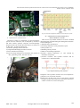
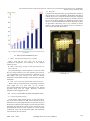
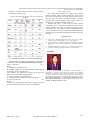
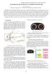
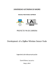
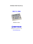
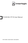
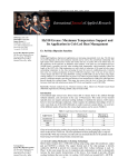
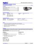
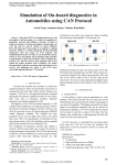
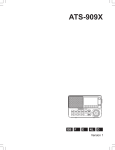
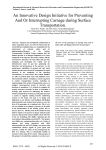
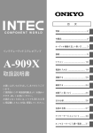
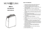
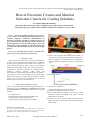
International Journal of Advanced Research in Electronics and Communication Engineering (IJARECE) Volume 4, Issue 3, March 2015 Heat in Electronic Circuits and Material Selection Criteria for Cooling Solutions Er. Pal Riya Bipradas Sanchita Dept. ETRX Research Student (Master Of Engineering) of Pillai Institute Of Information Technology,Engineering, Media Studies and Research affiliated to Mumbai University, India Abstract — Electronic cooling has made its way practically to every aspect of modern life from small components to scientific computers. Continuous miniaturization of electronic systems has resulted in a dramatic increase in the level of heat generated. This paper deals with levels of heat dissipated by various electronic products, where and which type of cooling technique is to be applied and rules to be followed while selecting materials for circuit cooling purpose. Index Terms— British thermal unit (BTU), critical heat flux (CHF), drop test (DT), printed circuit board (PCB). I. INTRODUCTION Field of electronics deals with construction and utilization of devices involving current flow through them accompanied by heat by heat generated in the amount of I2R where I is current flowing through the device and R is the resistance offered by device towards current flow. The heat generating components in electronic packages are microprocessors, transistors, resistors, batteries, solder joints, and semiconductors. The reliability of the electronics of a system is a major factor in the overall reliability of the system. When thousands and millions of components are packed in a small volume, heat level increases exponentially. The cooler the electronic device operates, more reliable it is. II. HEAT MANAGEMENT LEVELS There are three fundamental thermal management degrees in electronics analysis: Component level, Board level and and System level. Each has different objectives and analysis strategies. A. Component level Component level thermal management deals with: 1) Total number of components on PCB. 2) Spacing between each components on PCB. Fig.1: Number of Components and spacing between them. 3) Nature of die or grease attached (die/grease attach is a critical factor at component level thermal management as they can degrade the performance due to mismatch in thermal expansion of materials on either side of the bond line). Fig.2: Thermal expansion levels of each layer. B. Board level or PCB level Thermal management at this level deals with: 1) Thickness of component board (i.e. PCB). 2) PCB cooling depends strongly on the local air flow distribution, which is disrupted as air passes over the components on the board. 3) Decisions are made whether which cooling technique (fans or heat sinks or heat pipes or hybrid technique) to be used for PCB. Manuscript received March, 2015. Er. Pal Riya Bipradas Sanchita, PIIT (Pillai Institute Of Information Technology, Engineering, Media Studies and Research), affiliated under Mumbai University, Mumbai, India, Mobile no: 9869167976. 619 ISSN: 2278 – 909X All Rights Reserved © 2015 IJARECE International Journal of Advanced Research in Electronics and Communication Engineering (IJARECE) Volume 4, Issue 3, March 2015 Fig.5: Level of heat management needed by various electronic systems Fig.3: Heat Sink used to cool CPU PCB C. System level or enclosure level Electronics cooling is a challenging .Air flow through the system cools the electronics, but is disrupted by electronics and other internal geometry. Improper enclosure/package design also alters the air flow direction and acts as obstacle in air flow path. System level deals with: 1) Enclosure /package material selection. 2) (Length*breadth*height) parameter selection. 3) Vent (ventilation) size design. 4) Type of cooling technique to be used (like: fans, number of fans, positioning of fans, heat sink size etc). III. PROBLEMS FACED DURING HEAT MANAGEMENT OF PCBS There are lots of problems needed to be faced or handled during designing and establishing heat management solutions. Those challenges are: 1) Miniaturization of PCBs area. 2) Increasing demand in circuit performance speed. 3) Final product cost. 4) Fulfilling certain protocols. 5) Effect of surrounding temperature. 6) System‘s internal temperature (i.e. heat released by individual components). 7) Junction resistance, heat spreader resistance and air resistance are 3 important hurdles. Fig.6: diagram illustrating 3 main resistances Fig.4: Fans used to cool internal air of the enclosed CPU 8) Negative role of system‘s vibration on its own components. 9) Negative role of external vibrations. 10)Dust (more the dust level, more it will result in internal heating as proper heat transfer from individual component‘s surface to exterior air will not take place). 620 ISSN: 2278 – 909X All Rights Reserved © 2015 IJARECE International Journal of Advanced Research in Electronics and Communication Engineering (IJARECE) Volume 4, Issue 3, March 2015 Fig.9: Temperature Vs Leakage power B. Numerical illustration of Time, Power and Temperature relation Fig.7: Causes of overheating of PCBs It is nice to have at least 1 approximate mathematical approach to estimate how hot the system will become before IV. INFLUENCE OF TIME ON HEAT DISSIPATION building the actual device/system and its modeling. We know that electrical heat dissipation is measured in watts. The A. Time, Power and Temperature relation energy in joule and heat is measured in calories. Consider we have 300g of water. If the water is heated for Heat is no longer a number but a distribution. There exist a 10sec at 10Watts.What will be the amount of temperature rise positive feedback loop between time, power and temperature. then???? Answer is: This is best explained using below fig.7. Watt = Joules / time (1) Energy = watt* time (2) Energy = 10watts *10sec (unit: joule) Energy = 100 Joule 1Joule is 4.185 calories them 100Joules would be 418.5 Calories. So Temperature rise (0C) = calories / gram (3) 0 C = 418.5/300 0 C = 1.395 Hence approximately we can say 10seconds of operation would cause a temperature rise by 10C if 10W of supply is used. C. Heat / Power Dissipation Model TABLE.1: THERMAL TO ELECTRICAL DOMAIN Electrical Domain Variables Units Current (I) Amperes (A) Voltage (V) Volts Electrical resistance (R) Ohms (Ω) Electrical Capacitance (C) Farads Thermal domain Variables Units Power /heat Watts (W) flux (PD) Temperature Centigrade (T) (0C) Thermal 0 resistance C/W (Rθ) Thermal capacitance Joules/0C (Cθ) Heat /power dissipated by individual components can be calculated by:Ʈ (tou) = Cθ x Rθ (4) Cθ = specific heat x density x volume (5) Fig.8: Flow diagram relating time, power and temperature. Cθ = [(J/kg K) x (Kg/m3) x (m3)] units Leakage power increases exponentially with temperature at PD = Tc / [Rθ x (1-e –t/ Ʈ )] (6) small technology node. 621 ISSN: 2278 – 909X All Rights Reserved © 2015 IJARECE International Journal of Advanced Research in Electronics and Communication Engineering (IJARECE) Volume 4, Issue 3, March 2015 Fig.10: Power dissipated by individual component. TABLE.2: HEAT DISSIPATION LEVELS BY CERTAIN DEVICES Devices 8086 processor Level of heat dissipated (at 280C) 2.5W BJT Transistor 0.5W Low voltage audio amplifier 1.25W General purpose diode (IN 4007) MOSFET Transistor 500mW PCBs(printed circuit board) Semiconductor lasers 0.3W (at 280C) to 481W (at 1750C) 5W to 100W (depends on number of components and PCB size) 2000W Microwave devices 1000W Radar system 2000W flux at around 50W/cm2, then alone use of heat sinks will work good. Below Table.4 properly explains which cooling option/technique to be used for electronic circuits generating heat flux (in: W/cm2) at various levels. Heat flux is defined as the amount of heat transferred per unit area per unit time from one surface to another. Critical Heat Flux (CHF) is the peak heat flux .Any further increase in flux level above CHF would cause the circuit/component to get damaged. TABLE.4: HEAT REMOVAL OPTIONS Techniques Heat sink Heat pipe EDIFICE (embedded droplet impingement for integrated cooling of electronics) Simple copper heat pipe using water as coolant Spray cooling Jet cooling Water (2 phase method) Standard fans Copper plates Heat flux level (W/cm2) 50 10 to 300 100 110 150 to 200 160 200 350 790 TABLE.3: CRITICAL TEMPERATURE LIMITS Temperature in (0C) -44 -55 60 85 125 150 160 1400 Devices Minimum automotive operating temperature Semiconductor storage lowest temperature Metal surfaces are painfully hot Max temperature of electrolytic capacitors Max operating temperature of digital circuits Max allowable junction temperature Power transistor junction temperature Melting point of all semiconductor products Fig.11: Jet cooling rate Vs Spray cooling rate V. HEAT REMOVAL OPTIONS AVAILABLE A. Options available Vast options are available to remove heat from circuits/PCBs. Before going for any particular technique, one should always find the total amount of power dissipated by the board. This can be done by going through the user manual provided for every components or one can directly measure heat released by individual components by using heat sensors. Example: If your PCB board generates maximum heat / heat 622 ISSN: 2278 – 909X All Rights Reserved © 2015 IJARECE International Journal of Advanced Research in Electronics and Communication Engineering (IJARECE) Volume 4, Issue 3, March 2015 B. Drop test Consider a thin heat pipe made up of good thermal conductive material which is to be embedded in PCB. Before attaching it to PCB, drop test is carried out where the heat pipe is dropped from variable heights for approximately say 10 times. If at all it survives all 10 drops without any mechanical (surface crack) failure, it would be embedded in the PCB. But drop test does not guarantees 100%.Drop test is very common in mobile phones to test strength of the mobile screen, its enclosure as well as of the heat sink attached to it. Fig.12: Graph illustrating Heat cooling options Vs amount of flux that can be removed VI. HEAT MANAGEMENT RULES A. Rule 1: Life span and Temperature relation Rule 1 state that for every 100C rise in circuit or component‘s temperature, the reliability or the lifespan reduces by 50%. B. Rule 2: Little finger test (for circuits operated in free air (not enclosed)) Use your little finger to touch capacitors, resistors etc when they are being operated. If you can maintain your touch for very long duration (if hottest component is bearable by your little finger) then your circuit is less likely to develop temperature related failure and thus will not need any heat sink attachment. Fig.13: Drop test done on mobile phone to test mechanical strength of attached heat sink C. Rule 3: for circuits operated within enclosed structure When circuit is in enclosed form, you probably cannot use ‗little finger test‘. For such cases, go for product‘s exterior/environmental operating point stated in user manual provided along with the circuit. Basically, maximum temperature limit suggested is 600C. VII. CONCEPT OF DOUBLE PAYING AND DROP TEST A. Concept of Double Paying We all always suffer ‗double paying‘. At the front end we pay in the form of dollars or INR for the amount of power utilized to run circuits/equipments/devices as well as we pay at the back for reduction in the lifespan of circuits because of heat generated. In mobile devices, drop test are carried out to test for mechanical crack on screen, enclosure as well as internal components along with attached heat sinks (heat absorbing source/material) are also tested. 623 ISSN: 2278 – 909X All Rights Reserved © 2015 IJARECE International Journal of Advanced Research in Electronics and Communication Engineering (IJARECE) Volume 4, Issue 3, March 2015 B. Mechanical reliability Consider an example where we need to screw a small heat sink with the PCB. Heavily tightening the heat sink can severely put stress on PCB and that will result in cracking of PCB as well as electrical path. Thus reducing mechanical reliability. Fig.15: diagram showing the cause of crack in PBC C. Thermal Reliability If the rate at which heat produced by component (such as IC (integrated circuit)) is higher than the rate at which heat is releases to the environment then because of tremendous increase in IC‘s temperature, IC will burn out. D. Chemical Reliability If I am using 2 general purpose batteries (attached on the PCB) as DC source and if at all thermal reliability limit fails then high internal heat within the battery will cause its chemical to leak. Fig.14: Drop test of heat pipe which is to be embedded in PCB VIII. HEAT UNITS Heat is inevitable. Heat can be measured in BTU (British thermal unit) or watts or tons of air. But to avoid confusion of units, there is a simple relation i.e: power consumption is stated in watts. Heat rise is stated in BTU. Cooling systems such as air conditioners are stated in ‗tons of air’. 1 watt-hour = 3.14BTU (7) 1BTU = 1055Joules (8) 1BUT = 252 Calories (9) 1 Ton of air = 1200 BTU (10) IX. RELIABILITIES ASSOCIATED WHEN DEALING WITH HEAT MANAGEMENT Reliability means operation of the complete unit/system or component at maximum speed at maximum hours without facing any problems in electrical, thermal, mechanical or electrochemical failure. A. Electrical reliability Dealing with electrical reliability, heat absorbing or control materials like heat sinks when used in circuits, should be soldered or screwed in such a way that it does not results in any short circuit path with the PCB tract. X. MATERIAL SELECTION CRITERIA TO FORM A GOOD HEAT EXCHANGER Any material you select (whether metals, gases or liquids) to form a good heat exchanger, it must have the following properties: 1) Strong bonding. It implies that atoms separate to a lesser degree when they come in contact with high heat fluxes. 2) Simple structure. 3) High value of fracture strength. 4) Low value of thermal expansion coefficient. 5) High thermal conductivity. 6) Low cost. 7) High value of phase transformation in case of liquids. 8) Low value of elastic module as high vibration leads to thermal and mechanical reliability failure. 9) Low density. 10) High thermal shock resistance. 11) Lowest level of impurity. Thermal conductivity will reduce if impurity level is high. Aluminum (Al) and copper (Cu) satisfies above properties. Below table illustrated the reason why Al and Cu are best preferred materials to form good heat exchanger/ absorber .Al is used in those applications where weight 624 ISSN: 2278 – 909X All Rights Reserved © 2015 IJARECE International Journal of Advanced Research in Electronics and Communication Engineering (IJARECE) Volume 4, Issue 3, March 2015 reduction is of high concern and if not so high concern is XII. CONCLUSION required then copper is used. The market driven demand for higher power density TABLE.5: PROPERTIES OF HIGHLY USED HEAT ABSORBER MATERIALS designs inevitably leads to higher temperatures at the circuit level. The interconnection of power semiconductor devices and heat sink often forms a limiting bottleneck. Carefully choosing and properly applying heat cooling material is mandatory to get the best possible performance. Through this paper, I have tried to clearly explain overheating causes, contribution of time and what type of cooling solution to be used for various heat levels is also detailed over here. One must not forget about drop test which is one of the important criteria in designing and manufacturing cooling solutions especially when dealing with heat pipes and heat sinks. REFERENCES [1] [2] [3] Jebin Jacob, ―Thermal Management Studies Using Phase Change Materials For Electronic Packages‖, Vol.V, April-June,2014. Dan Pound, Richard W. Bonner , ―High Heat Flux Heat Pipe Embedded in MCPCB for LED Thermal Management‖ , ITHERM Conference 2014. Mahendra Wankhede, Vivek Khaire, Dr. Avijit Goswami, ―Evaluation of Cooling Solutions for Outdoor Electronics‖, September 2007 AUTHOR XI. THERMLA SHOCK OF COOLING MATERIALS Materials when selected to form electronic circuit cooling solution must have high thermal shock resistance (TSR). TSR = (σ*K)/(E*α) (11) Where: σ = strength of selected material K = thermal conductivity of selected material (metals have K in the range (20-40), polymers (0.3) and ceramic (2- 50). This gives a reason why Al and Cu are mainly used to form heat cooling solution) E = elastic module of selected material α = thermal expansion coefficient of selected material α= (Lf-Li)/L0*(Tf-To) (12) Where: To and Tf are initial and final temperatures in Kelvin, Li and Lf are initial and final dimensions of the selected material. Er. PAL RIYA BIPRADAS SANCHITA received Bachelor Of Engineering in Electronics from PIIT (Pillai Institute Of Information Technology, Engineering, Media Studies & Research) under Mumbai University. Currently pursuing Master of Engineering. Her research areas are Power Electronics and Optical Communication. She is the author of (1) ‗Free Space Light Communication‘ (2) ‗Negative Role of Atmosphere On Free Space Light Communication‘. She has designed Electronics PCB project for HPST POWER COMPANY in KBR . 625 ISSN: 2278 – 909X All Rights Reserved © 2015 IJARECE