1
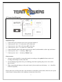
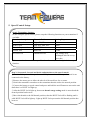
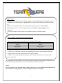
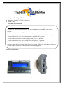
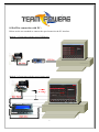
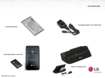
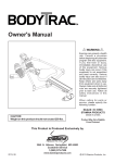
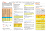
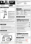
(Designed & Manufactured by RC EXPLORER TEAM)
Radon Brushless Speed Control System User Guidelines
1. Technical /Specifications:
Radon- Pro
Radon-Sport
Continuous current:
140A
95A
Burst Current (10sec):
720A
490A
3.7V LiPo
2 ~3cells
2 cells
1.2V NiMh/NiCd
4-6 cells
4-6 cells
Linear 6V/3A
Linear 6V/3A
~46g
~46g
~39.5x30x30
~39.5x30x30
4.5 Turn or over
5.5 Turn or over
Model:
Battery Input:
BEC Output:
Weight (not include wiring & fan):
Dimension(L x W x H) mm
(Include the fan assembly to the ESC)
Motor limit with 2cell x 3.7V Lipo.
The motor timing is at 0 degree
2. Features:
*
*
*
*
*
*
*
Ultra-smooth, Precise Throttle and Braking Control
Compatible with Sensored/Sensorless Brushless Motors
Data Analysis Capability(RPM, Low voltage and ESC temperature)
HotWire PC Interface for Advanced Programming and Updating
Easily Programming through the Program card
Built-in one touch On/Off switch with LED
Bulit-in Low voltage cut-off, Overheat protection and signal loss protection
3. Component Included:
- Speed control, Power capacitor, BEC wire, 25x25mm Fan, sensor wire, USB wire and USB device
Noted: Program card is not included in the package
1
4. Connection Diagram:
Installation Tips:
1. Connect the speed control to the receiver position channel 2.
2.
3.
4.
5.
Connect power wire “A” to the motor “A” solder-tabs
Connect power wire “B” to the motor “B” solder-tabs
Connect power wire “C” to motor “C” solder-tabs
Connect the hall sensor cable between the speed control (underneath the solder taps) and motor
6. Connect power wire ”+” to battery “Plus” sign
7. Connect power wire “-“ to battery “Minus” sign
Point to notes:
1. All power wires should be connected properly according to the symbol indicator and avoid
creating solder bridges on the solder tab
2. Avoid soldering longer than 5sec per soldering joint when replacing the power wires on the
speed control
3. When connecting the battery to the speed control, please make sure the battery + or – should be
connected properly.
Please make sure to follow the above tips and notes to install the speed control, otherwise, the speed
control may be destroyed due to the improper connection of the wires.
2
5. Speed Control Setup:
Step1: Transmitter Settings:
Before setup the speed control, please setup the following functions on your transmitter if
available:
Functions description
Name in Radio
Setting Request
Throttle Travel
High ATV, EPA
100%
Brake Travel
Low ATV, EPA, ATL
100%
Throttle Exponential
EXP, EXPO
Set at 0
Neutral Trim
Sub Trim
Center
Servo Reverse
Throttle Reverse
Any setting, keep
unchanged after the set-up
procedure
If the transmitter does not have any of the above function, it is already in basic setup
function.
Step 2: Set neutral, forward and brake endpoint data to the speed control:
◎Switch off the power of the speed control and please make sure the speed control is not
connected to the battery.
◎Remove the motor gear to allow the wheels of the model are free to rotate.
◎Switch the transmitter on and move the transmitter throttle stick to the neutral position.
◎Connect the battery to speed control and press and hold the on/off button to turn on the unit
until there is a BLUE Led light up.
◎After the BLUE Led is light up, that mean throttle range setting mode is entered and the
neutral position has been set.
◎Move the throttle to the full throttle position, then the BLUE Led will be flashing until a
solid BLUE Led will be light up. Light up BLUE Led represent the full throttle position has
been set.
3
Step 2: cont…
◎Move the throttle stick to the full brake position, then the RED Led will be flashing until a
solid RED Led will be light up. Light up RED Led represent the full brake position has been
set.
◎Move the throttle stick back the neutral position again, then the flashing RED &
BLUE(purple color) Led will be light up that means throttle range setting has been
completed.
◎The speed control will be ready for use when it powers is off and on again.
Step 3: Double check the speed control function:
The speed control can be checked based on the below LED status.
Functions
Status LED Color
Neutral
BLUE
Full Throttle
RED+ BLUE
Full Brake
RED
◎If the above LED status is correct corresponding to the speed control function, then the
setup procedure has been completed and it is ready for using
◎If there is a mistake during the setup procedure. Please turn off the unit and repeat the
Step 2 procedure.
In setup mode, the speed control will store the neutral, forward or brake position setting inside the
built-in memory and will not lose even if it is disconnected from the battery.
Notes:
If it can’t enter to the “throttle range setting”, please try to reverse the Throttle and brake in
the transmitter setting and go to step 2 to setup the speed control again.
4
6. Program Card Specifications:
* Dimension: 91mm(L) x 53(W) x 18mm(H)
* Weight: ~68g
Program Card Operation:
Step 1: Connection with Speed control:
◎Switch off the speed control power and take out the speed control BEC wire from the
receiver.
◎Connect the speed control BEC wire to the Program card connector.
Please make sure the speed control wire is connected properly based on the below description.
- Connect BEC white color wire to the program card pin at (‘S’) position.
- Connect BEC red color wire to the program card pin at (‘+’) position.
- Connect BEC black color wire to the program card pin at (‘-’) position.
◎Connect the battery to the speed control and turn on the unit. From the start, there should be a
message ‘Radon Series Program Card’. If any key pressed, LCD screen will show the firmware
version number for around 1s and then enter to Item Setting Mode
Program Card Picture:
5
Step 2: How to program the mode function setting through the setting card:
◎ Press the Mode key to select the mode setting
◎ Press the Item key to select the mode setting values
◎ Press the Update key to update each setting values of each mode
◎ Press the Reset key to restore all mode setting to factory default setting
◎ Press and hold the Mode and Item key together for around 2s will enter to Data Analysis
mode which can be reviewed RPM, Low voltage and ESC temperature
7. LED Indicators:
◎ If RED Led is flashing when the speed control is in the run, that mean the Low Voltage
function is activated and reduce the power to the motor. It show the battery is lower than
expected value..
◎ If BLUE+RED is flashing when the speed control is in the run, that mean the Overheat
Protection is activated, the speed control will cut around 50% power delivery to the motor to
avoid the burning problem.
◎ If BLUE LED keep blinking at neutral position, it indicates it is in Zero Timing /Blinking
Mode.
6
8. HotWire connection with PC:
Below are the two methods to connect the speed control to the PC interface.
Method 1: Connection with the use of USB device
Method 2: Connection with the use of setting card
7
◎ The PC interface software can be downloaded through the website address.
http://www.team-powers.com/radon_pg/TP_Radon USB link V1.0.exe
or it can be downloaded from the www.team-powers.com home page directly.
◎Support Window System: XP SP2, Windows7 and Windows8
How to program the mode function setting through PC interface:
◎ Install TP_Radon_USB_Link program according to the installed instruction
◎ Use method 1 or 2 to connect the speed control to PC through the USB wire
◎ Press “Radon Software” icon to open the Radon PC program interface. If the
setting card or usb device is connected to PC properly, the “USB”and “ESC”icon
will be lighted up. That mean all mode setting is uploaded to PC and ready for
adjustment.
◎ If it is using the setting card to connect to PC, it needs to connect the external 2cell
(7.4V) battery. After the speed control power is on, if the PC interface is connected
with the speed control properly, USB”and “ESC”icon will be lighted up. That
mean all mode setting is uploaded to PC and ready for adjustment.
◎ After all mode setting is set, press “Update Setting” icon to update the settings
Point to Notes:
◎ Press “Reset to default” icon to reset all mode setting values to factory default setting
◎ Press “Firmware update” icon to upgrade the speed control firmware code
◎ About all other mode setting descriptions, it can be reviewed through the PC interface
descriptions.
8
9.Troubleshooting Table:
Symptom
Cause
Action to take
No motor and servo functions
Wiring problem
Check wire and connectors
Wrong polarity when connecting the
Correct the polarity when connecting
BEC wire to the receiver
the BEC wire to the receiver
Transmitter, Receiver or Battery
Replace the components one by one
defective
Speed control defective
Send for repair
No motor function, but servo is
Wiring problem
Check wire and connectors
working
Sensor wiring defective/missing
Change other wire
Motor defective
Change other motor
Speed control defective
Send for repair
Sensor wiring defective
Replace the wire
Motor or Sensor board defective
Change other motor or sensor board
Power Capacitor failure
Replace the power capacitor
Radio interference
Change the components location
Speed control defective
Send for repair
While accelerating, motor stutters
Motor runs at constant slow speed Transmitter settings changed after
and never stops
Radio Interference
Repeat set up procedure
setup
Humidity/water in speed control
Dry the speed control
Transmitter batteries empty
Replace transmitter batteries
Bad battery connection
Check wire connection
Receiver, transmitter or servo
Replace the components one by one
defective
Receiver or antenna too close to
power wires of motor and battery
9
Change the components location
10.Warning Notes:
-
-
Please read the following instructions carefully before starting to use the unit. For those users
that do not have experience to use it, please seek help from the professional users.
Please make sure the voltage applied to the unit is in the operating range and the battery + and –
sign should be connected properly to the power cord of the unit. If battery +, - is reversed to
connect to the unit, the unit will be burnt out.
In case there is an abnormal operation in the unit, please turn off the unit and go to section 4 to
setup the speed control again.
11. 45 days Warranty Services:
All products are manufactured according to the highest quality standards. Team Powers guarantees
this product to be free from defects in materials or workmanship for 45 days from the original date
of purchase verified by sales receipt. This limited warranty doesn’t cover incorrect installation,
operations that are instructed to users, damaged by crash or any natural disaster.
This also applies the below things on:
◎ Cut off the original power plug
◎Receiver wire and/or switch wire damaged
◎Mechanical damage of the case
◎Mechanical damage of electronic components/PCB
◎Humidity/Water inside the speed control
◎Soldered on the PCB (except on solder pads)
◎Connected speed-control with reversed polarity
Before you send in this product for repair, please try to eliminate all other possibilities or improper
handling by checking all other components in your model and the trouble shooting guide. If the
products are sent in for repair, which do operate perfectly, we have to charge a service fee according
to our pricelist.
With sending in this product, the customer has to advise Team Powers if the product should be
repaired in either case. If there is neither a warranty nor guarantee claim, the inspection of the
product and the repairs may be charged with a fee at the customers expense according to our price
list. A proof of purchase including date of purchase needs to be included. Otherwise, no warranty
10
can be granted. For quick repair-and return service, please add your address and detailed description
of the malfunction.
If Team Powers are unable to service those defective products that are no longer exist in the market,
we shall provide you with a product that has at least the same value from one of the successor
series.
The specifications like weight, size and others should be seen as in this user guideline. Due to
ongoing technical improvements, which are done in the interest of the product, Team Powers does
not take any responsibility for the accuracy of these specs.
Distributor Service:
◎Package your product with sales receipt together with the detailed description of malfunction.
◎Send parcel to your national Team Powers dealer/distributor.
◎Distributor repairs or exchanges the product.
◎Shipment back to your usually by COD (cash on delivery), but this is subject to the general
policy of your national Team Powers dealer/distributor.
If any further information need upon reviewing the instruction, please feel free to contact
[email protected]. For more about Team Powers product information, please go to the
below web sites. http://www.rc-explorer.com or http://www.team-powers.com.

11