1
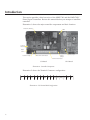
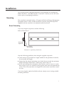
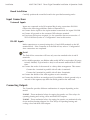
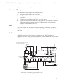
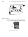
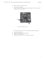
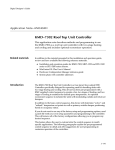
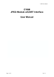
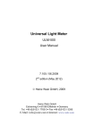
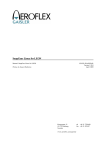
Installation & Operation Guide
(KMD-7102 Shown)
KMD-7101/01C and KMD-7102/02C
Direct Digital Controllers
885-019-02B
1
Introduction
This section provides a brief overview of the KMD-7301 and the KMD-7301C
Direct Digital Controllers. Review this material before you attempt to install the
controller.
Illustration 1 shows the major controller components and their locations.
Mechanical Relays
LEDs
Pull-Up
Resistors
RJ-12
Conn.
Isolation Lamps
Reset Jumper
Power
Jumper
Terminal Connectors
End-of-Line Terminators
I/O Board
CPU Board
Illustration 1. Controller Components
Illustration 2 shows the Terminal Connector configuration.
B
A
GND
IN1
IN2
IN3
IN4
LOW MED
HI
GND GND
Illustration 2. I/O Terminal Block Configuration
2
HW
VLVS
CW
Installation
This section provides important instructions and guidelines for installing the
KMD-7101/7101C and KMD-7102/2C Controllers. Carefully review this information prior to attempting installation.
Mounting
The controller is mounted inside a UL-approved Enclosed Energy Management
Equipment Panel or other suitable protective enclosure using the snap-track
supplied with the controller or an optional molded enclosure.
Board Mounting
If you are using the snap-track, read the following:
Refer to Illustration 3.
Washers
(optional)
Max Screw
Head Height
Illustration 3. Typical Snap-Track Section
Note the following guidelines when using the supplied snap-track:
◆
Track sections are provided in a length suitable for the purchased controller,
do not modify the length.
◆
Ensure that the selected mounting screw heads do not exceed the maximum
height indicated in Illustration 3, shorts may result if they do..
◆
If you are installing the track against a hard surface, such as wood, it is advisable to place one or two washers on the opposite side of the track beneath the
screws. This will ensure there is enough flex in the track to install the controller card.
If you are using the optional molded enclosure, simply secure it using suitable
mounting hardware.
3
Installation
KMD-7101/7101C Direct Digital Controller Installation & Operation Guide
Board Installation
Carefully position the controller board in the provided mounting tracks.
Input Connections
Universal Inputs
Inputs are connected to the I/O terminal block using connections IN1–IN4.
Observe the following guidelines. (Refer to Illustration 2.)
◆
Connect device inputs to the input terminal connections for inputs IN1–IN4.
◆
Connect all grounds to the common GND reference terminal.
◆
If no input pull-ups are required, (i.e. the controller does not souurce the +5
VDC to the device) refer to “Configuration” later in this section.
RS-485 Inputs
Make connections to a network using the A, B and GND terminals on the I/O
terminal block. If the Controller is at the End-of-Line, refer to “Configuration”
after connections are completed.
Detail
The End-of-Line connection will have only one wire attached to the A and B
terminals.
◆
For reliable operation, use Belden cable model #82760 or equivalent (18 gauge,
twisted, shielded, 50 picofarads or less) for all network terminal block connections.
◆
Connect the nodes of the network in a daisy-chain arrangement. This means:
Connect the A terminal in parallel with all other A terminals.
Connect the B terminal in parallel with all other B terminals.
◆
Connect the shields of the cable together at each controller.
◆
Connect the shields to an earth ground (if available) or chassis ground only at
one end of the segment; tape back the shield ground at the other end.
Connecting Outputs
The Controller provides different combinations of outputs depending on the
model:
7101/01C - Three mechanical relays for staging fan speeds, two Triac relays for
operating heating and cooling valves and three LED outputs.
7102/02C - Three mechanical relays for staging fan speeds, one mechanical relay
for an auxiliary heating element, two Triac relays for operating heating and
cooling valves and three LED outputs.
4
KMD-7101/7101C Direct Digital Controller Installation & Operation Guide
Installation
Connections are made as follows:
Mechanical Relays
The mechanical relays require the following steps.
1.
2.
3.
4.
Bring the control leads to the controller.
Install spade lug connectors on each lead. We recommend a crimp lug
connectors.
Connect the control lead to the N.O. lug on the relay.
Prepare a common lead connection with spade lug for each relay common.
These are connected together, then to L1. (Refer to the wiring diagram
samples in Illustrations 4 and 5.)
LEDs
The LED outputs are connected to the corresponding connections on the STE5015-10 thermostat to provide visual indication of the fan speed: High, Medium
and Low.
RJ-12
An RJ–12 connector is provided for connection to the KMC NetView or
Netsensor devices. Simply place the appropriate cable connector in the provided
RJ–12 connector and connect the other end to the device.
APPLICATION DRAWING FOR KMD-7101
FCU WITH 3-SPEED FAN AND 24VAC HOT
AND CHILLED WATER VALVES
M
HIGH
MED
FAN COIL UNIT
LOW
L1 L2
H
C
C
C
KMD-7101
N.O.
N.O.
COM
COM
N.O.
COM
HWR
HWS
OUT1-FANSPEED
FROM PREV. DEVICE "A"
FROM PREV. DEVICE "B"
TO NEXT DEVICE "A"
TO NEXT DEVICE "B"
CWR
CWS
T)
MP STP
TE
M
OM ROO
O
(
R
B
A
GND
IN1
IN2
IN3
LV
LV
VA
VA
OL
CO
AT
HE
IN4
LOW MED
HI
GND GND
HW VLVS
CW
24VAC
A B C
120VAC
STE-5015-10
D E F
12VDC DRIVES LED'S IN STAT
Illustration 4. Typical Wiring Diagram (KMD-7101)
5
KMD-7101/7101C Direct Digital Controller Installation & Operation Guide
L1
L2
HIGH
MED
LOW
FAN COIL UNIT
L1 L2
C
R
C
H
KMD-7102
N.O.
COM
N.O.
N.O.
COM
COM
A
GND
IN1
IN2
IN3
IN4
LOW MED
HI
GND GND
HW
VLVS CW
24VAC
A B C
STE-5015-10
B
CO
OL
VA
LV
HE
RO
O
AT
VA
LV
MT
E
(RO MP
OM
ST
PT
)
FROM PREV. DEVICE "A"
FROM PREV. DEVICE "B"
TO NEXT DEVICE "A"
TO NEXT DEVICE "B"
W
CWS
CWR
OUT2-AUX-HEAT
OUT1-FANSPEED
B
ELECTRIC
REHEAT
COM
M
N.O.
Installation
120VAC
APPLICATION DRAWING FOR
KMD-7102 FCU WITH 3-SPEED
FAN AND ELECTRIC REHEAT
D E F
Illustration 5. Typical Wiring Diagram (KMD-7102)
Board Configuration
Configuration settings may be required for the inputs or the RS-485 connection.
If you must deactivate pull-ups on the inputs or set the end-of-line termination
for the RS-485 connection, refer to Illustration 6 to locate the switches for these
settings.
Pull-Up
Resistors
End-of-Line Terminators
Illustration 6. Configuration Operion Locations
6
KMD-7101/7101C Direct Digital Controller Installation & Operation Guide
Installation
Input Pull-Ups
If the input provides its own power source (i.e. it is active, not passive) the input
resistor must be disconnected. Proceed as follows:
1.
2.
3.
Identify the resistor associated with the input connector (I1–I4). (Refer to
Illustration 6.)
Carefully clip resistor lead near the resistor body.
Raise the resistor body to open the connection. Make the certain the leads
do not touch.
Note:
You can remove the resistor rather than just clipping the lead, but if the input is
reassigned and the pull-up is required, you can reconnect the lead by repositioning the resistor body and applying a small amount of solder to the lead.
RS-485
If the controller is connected to the RS-485 loop in the end-of-line position (only
one wire is connected to the A and B terminals), the end-of-line terminations
must be activated. Proceed as follows:
1.
2.
Refer to Illustration 6 and locate the end-of-line jumpers near the isolation
lamps.
Position each jumper so it covers both pins on the associated connector.
Power Connection
Connect the 24 VAC supply voltage to the terminal block using the AC in and
GND connectors provided. (Refer to Illustrations 4 and 5.) Power is applied to
the controller when the power supply (or transformer) is plugged in, there is no
Power On/Off switch.
Network Configuration
Prior to operating the controller, it must be configured using the Hardware
Configuration Manager (HCM) application supplied with WinControl. Refer to
the WinControl XL User’s Manual and the MC Digital Applications Manual for
additional information.
Note:
All controllers on the same network must be configured for the same baud rate.
Programming
Refer to the KMC Digital Applications Manual for information on how to program the controller.
7
Operation
Once configured, programmed and powered up, the controller requires very
little user intervention.
Controls and Indicators
The following sections describe the controls and indicators found on the card.
Status LEDs
Two Status LEDs are located on the controller. One is positioned near the auxiliary relay on the I/O board and the other is located at the upper edge of the CPU
board. They are used to indicate the following:
RDY – This LED flashes rapidly whenever the controller is operating normally.
You can consider this the same as a power LED.
COM – This LED indicates when the controller is transmitting over the RS-485
network connection.
Isolation Lamps
Two Isolation Lamps are located near the RJ–11 connector. These lamps serve
three functions:
◆
Removing the lamps will open the RS-485 circuit and isolate the controller
from the network.
◆
If one, or both, lamps are lit, it indicates the network is improperly phased.
This means that the ground potential of the controller is not the same as other
controllers on the network
◆
If the voltage or current on the network exceeds safe levels, the lamps operate
as fuses to protect the controller from damage.
Resetting the Controller
If the controller appears to be operating incorrectly, or is not responding to
commands, you may need to reset the controller.
Note
Resetting the controller will restore the factory default configuration.
It may be necessary to re-configure the controller with HCM to establish normal
communications and operation. Reprogramming may also be required.
8
KMD-7101/7101C Direct Digital Controller Installation & Operation Guide
Operation
To reset the controller, proceed as follows.
1.
2.
Power off the controller.
Place a short on the RST jumper shown in Illustration 7. (You can install a
jumper if a spare is available.)
RST
WD
Illustration 7. Reset Jumper Locations
5.
6.
7.
8.
9.
Power up the controller. Wait until only the RDY LED flashes rapidly.
Power off the controller.
Remove the short from the RST jumper.
Replace the controller cover.
Power up the controller and re-configure it if necessary.
9
10
11
Disclaimer
The material in this document is provided for information purposes only.
The contents and the product(s) described herein are subject to change
without notice. KMC Controls, Inc. makes no representations or warranties
with respect to this document. In no event shall KMC Controls, Inc. be
liable for any damages, direct or incidental, arising out of or related to the
use of this document.
Important Notices
The KMC logo is a trademark of KMC Controls, Inc.©2003, KMC Controls,
Inc. All rights reserved.
No part of this publication may be reproduced, transmitted, transcribed,
stored in a retrieval system, or translated into any language in any form by
any means without the written permission of KMC Controls, Inc.Printed in
U.S.A.
Technical Support
If you have any questions about this technical document or need additional
details, please call KMC Controls technical services at 574-831-5250 or email us at [email protected].
KMC Controls
P.O. Box 497
19476 Industrial Drive
New Paris, IN 46553
U.S.A.
TEL: 574.831.5250
FAX: 574.831.5252
E-mail: [email protected]
12
885-019-02B