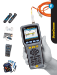
1
#61-846 & 61-848
®
HeatSeeker 160 and HeatSeeker® 320
Dual View Thermal Imaging Camera
Instruction Manual
Safety Warning:
The equipment described in this document uses a Class 2 laser. Under no account should
anyone look directly into the laser beam or the laser beam exit aperture, irreversible damage
to the eye may occur. The laser should not be operated when there are personnel in the
imager’s field of view.
Caution – use of controls or adjustments or performance of procedures other than those
specified in this document may result in hazardous laser radiation exposure.
© 2011 No part of this publication may be reproduced without prior permission in writing from IDEAL. Whilst IDEAL will endeavor to ensure that
any data contained in this product information is correct, IDEAL does not warrant its accuracy or accept liability for any reliance on it. IDEAL
reserves the right to change the specification of the products and descriptions in this publication without notice. Prior to ordering products please
check with IDEAL for current specification details. All brands and product names are acknowledged and may be trademarks or registered
trademarks of their respective holders.
ND-7521-3UK
Page 1 of 27
#61-846 & 61-848
Contents
1.
Page
CONTENTS OF THE CASE ................................................................................... 3
2. MAIN CONTROLS ................................................................................................... 4
2.1. BACK .................................................................................................................. 4
2.2. FRONT ................................................................................................................ 4
2.3. FUNCTION KEYS ..................................................................................................... 4
3. GETTING STARTED ................................................................................................. 5
3.1.
3.2.
3.3.
3.4
3.5.
3.6.
4.
4.1.
4.2.
4.3.
4.4.
4.5.
4.6.
4.7.
4.8.
5.
SWITCHING THE CAMERA ON/OFF .............................................................................
CHARGING THE BATTERY .......................................................................................
CHANGING THE BATTERY .......................................................................................
FOCUSING ........................................................................................................
SAVING AN IMAGE ...............................................................................................
TEMPERATURE MEASUREMENT ..................................................................................
5
5
5
6
6
6
FUNCTION BUTTONS.......................................................................................... 7
MOVING THE CURSOR ........................................................................................... 7
IMAGE ALIGNMENT .............................................................................................. 8
TURNING THE VISIBLE IMAGE OFF AND ON ................................................................... 9
THERMAL AND VISIBLE IMAGE BLENDING ..................................................................... 9
MANUAL CONTROL ..............................................................................................12
LIGHT ............................................................................................................12
IMAGE FREEZE ..................................................................................................12
MENU ............................................................................................................12
MENU STRUCTURE. .......................................................................................... 13
5.1.
INFRARED SETTINGS .........................................................................................14
5.2.
MEASUREMENT OPTIONS .....................................................................................15
5.3.
CAMERA SETTINGS ...........................................................................................17
5.4.
AUDIO SETTINGS .............................................................................................18
5.5.
IMAGE BROWSER .............................................................................................19
5.6.
DATE & TIME SETTINGS .....................................................................................19
5.7.
LANGUAGE SELECTION ......................................................................................20
5.8.
DISPLAY SETTINGS ..........................................................................................20
6. ADDING CAPTIONS WHEN SAVING IMAGES ......................................................... 21
6.1. VOICE MESSAGE ....................................................................................................21
6.2. TEXT CAPTIONS .....................................................................................................22
APPENDIX ................................................................................................................ 23
A1. EMISSIVITY TABLES .................................................................................................23
A2. FULL ICON LIST. ....................................................................................................24
A3. TECHNICAL SPECIFICATION .........................................................................................25
ND-7521-3UK
Page 2 of 27
#61-846 & 61-848
1. Contents of the Case
♦
Carrying Case.
♦
Camera.
♦
USB PSU and International Adaptors.
♦
CD – 61-846 Instruction Manual and ThermalVision™ 160 Software and
Software Instruction Manual
♦
USB Cable (Camera to PC).
♦
Quick Start Guide.
ND-7521-3UK
Page 3 of 27
#61-846 & 61-848
2. Main Controls
2.1. Back
Microphone
Function Keys 1 to 4
Speaker
Power Button
Centre Navigation
Key
Laser button
4 Navigation Keys
2.2. Front
Laser
Infrared lens
Light
Visible camera
Capture Button
2.3. Function Keys
The Function Key functions are indicated by the
icons or text displayed on the screen above them.
These functions vary according to the operating
options chosen by the user.
Function
Key 1
Function Function Function
Key 2
Key 4
Key 3
ND-7521-3UK
Page 4 of 27
#61-846 & 61-848
3. Getting started
3.1. Switching the camera on/off
Press the on/off button and
hold it for two seconds to
switch the camera on.
Press and hold for three
seconds to switch the camera
off.
After switching on, it will take up to 30 seconds for the infrared image to appear. The image
will periodically freeze for one or two seconds while the camera re-calibrates itself. This is
normal operation, and the time between these calibrations will increase as the operating
temperature of the camera stabilises.
3.2. Charging the battery
The camera’s battery is charged via the
USB port. A fully charged battery will last
approximately 5 hours. A green LED
indicates charging which turns to red when
the battery is charged.
Note: When the camera is connected to a PC via the USB cable it switches off and
the PC sees the SD card as an external memory.
3.3. Changing the battery
Open the lock on the battery cover and remove the cover
Remove battery.
Insert new battery, ensuring the
terminal pads are towards the front
of the camera.
Replace and lock the cover
ND-7521-3UK
Page 5 of 27
#61-846 & 61-848
3.4
Focusing
Gently rotate the lens clockwise and
counter-clockwise
to
focus
the
image.
♦ Remember to remove the lens cap.
Focus Bar
Out of Focus
Focused
When focusing a focus bar appears on the screen to assist in focusing the image. It
indicates the approximate distance in metres (in feet when °F is selected) of a focused
target from the camera.
3.5. Saving an image
Save image button
To save a live or frozen image, press the Save button once. If Caption Mode or Voice
Annotation has been turned on, a text caption or voice annotation can be attached to the
image (see section 6).
3.6. Temperature measurement
One of the key functions of a thermal imager is obtaining temperature information about the
scene. The IDEAL 61-846EU has a variety of measurement options to provide maximum
flexibility.
The display of temperature values and related items depends on the combination of the
measurement and display options selected. Temperature readings are displayed at the top of
the display. In the default mode, a single reading in °C indicates the temperature at the centre
point of the cursor. The other reading at the top of the display is the reflected temperature
setting (see section 5.1.). The temperature range within the scene is indicated by a scale on
the right hand side of the display.
ND-7521-3UK
Page 6 of 27
#61-846 & 61-848
4.
Function buttons
Function
Key1
Function
Key2
Function
Key3
Function
Key4
Pressing any of the Function Key buttons reveals the icons which indicate the functions of
these buttons. A box around the icon for Function Key1 or Function Key2 indicates that this
option is selected and this defines the operation of the navigation buttons. With the default
settings, the key functions are as follows:
Function
Function
Function
Function
Key
Key
Key
Key
1
2
3
4
toggles between Align Image and Cursor.
cycles through Visible on/off, Auto/Manual, and Light on/off.
toggles between Live and Freeze.
opens the menu.
See appendix A2 for a full list of Function Key button functions.
4.1. Moving the cursor
4.1.1.
Press Function Key 1
to toggle to the Cursor icon
emissivity value will be displayed at the top of the screen.
4.1.2.
Use the left/right and up/down navigation buttons to move the cursor to the
desired position.
ND-7521-3UK
. The
Page 7 of 27
#61-846 & 61-848
4.2. Image alignment
As the visible and thermal cameras are not co-axial the visible and thermal image may need to
be aligned. This is usually required when moving to view objects at different distances.
4.2.1.
Press Function Key 1
to toggle to the alignment icon
4.2.2.
Use the up/down and left/right navigation buttons
and visible images.
.
to align the thermal
Note The visible image is moved during alignment.
Examples of alignment.
Fully Aligned
Align left
Align right
Align up
Align down
Four pre-programmed alignment distances are included. These are at 0.5 metre, 1 metre,
2 metres and 4 metres ranges. With the alignment option selected by function key 1,
pressing the centre navigation button once aligns at 2 metres. Pressing the centre
navigation button repeatedly allows you to cycle through to 4 metres, 0.5 metre and 1
metre.
Note: These values appear in Feet if °F is selected.
ND-7521-3UK
Page 8 of 27
#61-846 & 61-848
4.3. Turning the visible image off and on
4.3.1.
Press Function Key 2
to toggle to the Visible On icon
4.3.2.
Press the centre navigation button
to toggle to Visible Off
4.3.3.
Press the centre navigation button
again to toggle to Visible On
.
.
.
4.4. Thermal and visible image blending
The camera can show a thermal image, a visible image of the scene, a mixed blend of both
visible and thermal, a thermal picture in the visible picture (PiP) and a blended version of the
thermal image in the PiP.
100% thermal
25% visible 75% thermal
50% visible 50% thermal
75% visible 25% thermal
100% visible
Picture in Picture
ND-7521-3UK
Page 9 of 27
#61-846 & 61-848
THERMAL ABOVE
THERMAL BELOW
In this example the parts of the scene with
temperatures above 15% of the displayed
temperature range are shown as a thermal
image; whilst the rest of the scene is shown
as a visible image.
In this example the parts of the scene with
temperatures that lie below 15% of the
displayed temperature range are shown as a
thermal image; whilst the rest of the scene is
shown as a visual image.
In this example the parts of the scene with
temperatures above 50% of the displayed
temperature range are shown as a thermal
image; whilst the rest of the scene is shown
as a visible image.
In this example the parts of the scene with
temperatures that lie below 50% of the
displayed temperature range are shown as a
thermal image; whilst the rest of the scene is
shown as a visual image.
In this example the parts of the scene with
temperatures above 85% of the displayed
temperature range are shown as a thermal
image; whilst the rest of the scene is shown
as a visible image.
In this example the parts of the scene with
temperatures that lie below 85% of the
displayed temperature range are shown as a
thermal image; whilst the rest of the scene is
shown as a visual image.
Thermal Above shows parts of the scene
which are at the upper end of temperature
range.
ND-7521-3UK
Thermal Below shows parts of the scene
which are at the lower end of temperature
range.
Page 10 of 27
#61-846 & 61-848
4.4.1.
Press Function Key 2
until the Visible On/Off icon appears
4.4.2.
If off
4.4.3.
Use the up/down navigation buttons to merge (blend) the visible and thermal
images. Repeatedly pressing the up button cycles through the options 0%,
25%, 50%, 75%, 100%, PiP.
press the centre navigation button
to toggle to Visible On
.
Blended
PiP
Up/Down
buttons
Thermal
Above
Thermal
Below
Left / Right Buttons
Blend – 0% -25%-50%-75%- 100% -0%
PiP – 25% - 50% - 75% - 100% - 25%
Thermal above/below -- in 5% steps
ND-7521-3UK
Page 11 of 27
#61-846 & 61-848
4.5. Manual control
The thermal image gain and offset are normally controlled automatically in order to give a
meaningful display on the screen. However, Function Key 2 offers the option of switching to
manual control if desired:
4.5.1.
Press Function Key 2
to toggle to the Auto icon
.
4.5.2.
Press the centre navigation button
to toggle to Manual
or Persistent
manual.
If Persistent manual is selected, then the manual settings are
stored. When the camera is switched on again, and Manual selected, the
stored span and level settings are used.
4.5.3.
Use the left/right navigation buttons to change the span of the displayed
temperature range.
4.5.4.
Use the up/down navigation buttons to change the level of the displayed
temperature range
4.5.5.
Press the centre navigation button again to revert to Auto.
4.6. Light
There is a visible illuminator for use in poor ambient lighting:
4.6.1.
Press Function Key 2
to toggle to the Light Off icon
4.6.2.
Press the centre navigation button
4.6.3.
Press the centre navigation button again to turn the light off.
to toggle to Light On
.
.
It is advisable to turn the light on only when necessary in order to conserve battery power.
4.7. Image freeze
Pressing Function Key 3 freezes both the infrared and the visible image. Pressing again
reverts to a live image. The image save facility works with either a live or a frozen image, but
once a frozen image has been saved the camera will revert to a live image.
4.8. Menu
Function Key 4 opens the menus. See section 5 for details of the menu structure.
ND-7521-3UK
Page 12 of 27
#61-846 & 61-848
5.
Menu structure.
Centre Navigation
button
Up/Down, Left/Right
navigation buttons
Function
Key1
♦
♦
♦
♦
♦
Function
Key2
Function
Key3
Function
Key4
Select the menu by pressing Function Key 4.
Navigate through the menu using the navigation buttons and press Function Key 3 to
select the required option. The highlighted item will have a box around it.
Use the up/down buttons to move in the selected list and select the required item.
Use the left/right buttons to change values and options for the specific item.
Press Function Key 4 to exit or Function Key 1 to go back to the previous menu.
Infrared
settings
Measurement
options
Camera
settings
Audio
settings
Display
Settings
Image
browser
ND-7521-3UK
Date & Time
settings
Language
selection
Page 13 of 27
#61-846 & 61-848
5.1.
Infrared settings
♦ Emissivity
Set the emissivity value between 0.10 and 1.00 using the left/right navigation
buttons.
Pressing Function Key 3 (ε Table) gives a table of emissivity values of common
materials from which a selection can be made.
Note that if more than one cursor is selected, individual emissivity’s can
be assigned to each cursor.
♦ Palette
Display the image using different colour palettes.
1. Ironbow
5.
High Contrast
2. Rainbow
6.
Rainbow 16
3. Isotherm Style
7.
Black Hot
4. Hot Metal
8.
White Hot
♦ Reflected Temp
Set this to the ambient temperature to correct for reflected radiation when an
emissivity of less than 1 is selected.
♦ Temp units
Choose between °C and °F.
♦ Integration
Chose an integration period from 1 (fast) to 4 (slow).
A longer integration time will reduce the noise in the image, but will slow down the
response to moving images.
♦ Interpolation
Choose Off or On.
This shows or hides the thermal image pixelation.
ND-7521-3UK
Page 14 of 27
#61-846 & 61-848
5.2.
Measurement options
This menu enables the selection of options for temperature measurements. The symbols
shown below indicate the icons shown for Function Key 1 when the various options are
selected.
♦
Cursors
. Choose from one to four cursors. When more than one cursor is selected,
the temperatures of all the cursors are displayed in a table or are tagged next to the
cursors (see section 5.8). When two cursors are chosen, the temperature difference
between them is also displayed. When one of the cursors is selected by Function Key 1,
it can be moved around on the display by the navigation buttons.
If two or more cursors are selected then individual emissivity values can be assigned to
each cursor. When an emissivity less than 1.00 is selected for a cursor, then that
cursor flashes on the screen.
Tabular temperature values
♦
Tagged temperature values
Tracking
.Select “High”, “Low”, or “High & Low” in order to track and measure the hottest
point, the coldest point, or both hottest and coldest points in the image.
♦
Area
.If this option is turned on, three different rectangular areas can be selected via
Function Key 1. The maximum, minimum, and average temperatures within the
designated area will be displayed in the top left hand corner of the display.
Note that the above three items are mutually exclusive, i.e. when one is turned on the
other two are disabled.
ND-7521-3UK
Page 15 of 27
#61-846 & 61-848
♦
Isotherms
.Select “High”, “Low”, or “High & Low” in order to highlight areas of the scene
with temperatures within a high (red) or low (blue) temperature band. The temperature
bands are adjustable by means of Function Key 1 and the navigation keys.
Red isotherm
♦
Blue isotherm
Combined isotherms
Temp. profile
.Select “Horizontal” or “Vertical” to enable a histogram of temperature values
along a horizontal or vertical cross section to be displayed on the right hand side or the
bottom of the display. The position of the cross section is indicated by small arrows at
the left and right or top and bottom of the image and can be adjusted by means of
Function Key 1 and the navigation buttons.
Vertical Profile
♦
Horizontal profile
Temp alarms
.Select “High”, “Low”, or “High & Low”. Visual and audio alarms will be
triggered if either cursor or a point within the designated area is higher or lower than a
set temperature. The high and low set temperatures may be adjusted by means of
Function Key 1 and the navigation buttons.
ND-7521-3UK
Page 16 of 27
#61-846 & 61-848
5.3.
Camera settings
♦
Caption mode
Select “On” to enable the addition of a text caption when saving an image.
Options will then be displayed when saving an image, to be selected by means of
Function Key 2 and Function Key 3.
♦
Auto off
Select “5 Mins”, “10 Mins”, “20 Mins” to allow the camera to switch itself off after
a defined period of inactivity in order to save power. There is also an “Always On”
option. In addition there is a “10 Min (dim)” where the LCD display is dimmed
after 10 minutes of inactivity.
♦
Camera reset
Select with Function Key 3 to restore the factory settings.
♦
Sequence Record
Select this to save a set of images of the scene. The images are saved to the
micro SD card and an be saved at intervals of 5 Sec, 10 Sec, 20 Sec, 30 Sec, 1
Min, 2 Min, 5 Min, 10 Min, 20 Min, 30 Min, 1 Hour and on Alarm. The alarm
setting works in conjunction with the high low alarm function. When the
temperature in the scene exceeds the user defined high alarm threshold
temperature an image is saved. Equally when the temperature in the scene goes
below the user defined low alarm threshold temperature an image is saved.
♦
Sequence Capture
If sequence record is selected, then this option is switched on and allows the
user to define the number of images to be saved. Choices available are 10, 50,
100, 500 and 1000 images.
ND-7521-3UK
Page 17 of 27
#61-846 & 61-848
5.4.
Audio settings
♦
Imager sounds
Select “Off” to mute all audible outputs.
♦
Voice annotation
Select “Individual” to add a voice message to each saved image.
Select “Session” to add a voice message at the start of a set of images (a
session ends when the imager is switched off).
Select “Combined” to add a common voice message at the start of a set of
images and add additional comments for each image.
♦
Voice playback
Select “speaker” or “headset” for the desired method of audible outputs.
♦
Volume
Select the volume of the audible outputs from 1 to 9.
If “Session” or “Combined” is selected the voice message is recorded before exiting
the audio settings menu by pressing Function Key 3. Recording is stopped by
pressing Function Key 3 again. Function Key 2 can be used to play back the
recorded message. Function Key 3 can be used to re-record if necessary.
ND-7521-3UK
Page 18 of 27
#61-846 & 61-848
5.5.
Image browser
The saved images are shown on the screen with the most recently saved image first.
Select the desired image by means of the navigation keys.
To display the selected image press Function Key 3.
To delete the selected image press Function Key 2, to confirm deletion press Function
Key 3.
When a stored image is displayed, press Function Key 3 to return to live imaging.
5.6.
Date & Time settings
a) Use the left/right buttons
to navigate in this menu, the item that can be changed
is highlighted in red. In the picture above the day (DD) 14 is highlighted.
b) Use the up/down buttons
to change the value.
c) The date formats can be changed by pressing Function Key 2 to cycle through DD-MMYYYY, MM-DD-YYYY and YYYY-MM-DD options. Pressing Function Key 4 will select the
option on the display.
ND-7521-3UK
Page 19 of 27
#61-846 & 61-848
5.7.
Language selection
To select a language move to the relevant flag. When the language is highlighted press
Function Key 3 to select.
5.8.
Display Settings
♦
LCD brightness
Select from 1 (low) to 9 (high) to control the screen brightness to save battery
power.
♦
Zoom
Allows the user to digitally zoom into the image. Options are X2 and X4 zoom.
♦
Cursor Type
Select how the cursor temperature values are to be displayed on the screen. The
choice is between a tabular display or a tag next to the cursor.
♦
ε
Choose whether or not to display the reflected temperature. Only applicable
when emissivity is selected to be less than 1.
♦
Temp. Units.
Choose whether or not the temperature units (°C or °F) are displayed on the
screen.
♦
Colour Scale
Chose whether or not the colour scale is to be displayed.
♦
Icon Timeout
The Icons above the 4 Function Keys can be displayed either continuously or for
10 seconds after a Function Key is pressed.
ND-7521-3UK
Page 20 of 27
#61-846 & 61-848
6. Adding captions when saving images
6.1. Voice message
When saving an image with Individual Voice Annotation turned on, there is the option of saving
a voice message with each image. The screen shots below describe the procedure:
a) Do you wish to attach a voice message
to this saved image?
Function Key 2 for no
. Function Key 3
for yes
.
c) Stop Recording
stop.
Function Key 3
to
e) If caption mode is selected this option
will now be offered to save a text caption
(see 6.2).
b) Start voice recording?
yes.
Function Key 3 for
d) Option to Re-record the voice message?
Function Key 2 for Yes
Function Key 3 for
No
f) Image with voice message is being saved.
Playback
The voice recording can be played back when viewing saved images in the browser.
Note:
The abort Icon
on Function Key 4.
Pressing Function Key 4 at any stage aborts the saving process.
ND-7521-3UK
Page 21 of 27
#61-846 & 61-848
6.2. Text captions
When saving an image with Caption Mode turned on, there is the option of attaching a text
caption to each image. The screen shots below describe the procedure:
a) Do you wish to attach a text caption message to this image?
Function key 2 for No
Function key 3 for Yes
2. Use the up/down arrow buttons to cycle
through letters and numbers until the one
required appears. The available symbols
are:
ABCDEFGHIJKLMNOPQRSTUVWXYZabcdefg
hijklmnopqrstuvwxyz0123456789
3. Use the left/right arrow buttons to move to
the next space and repeat the above step
until the caption is completed.
b) Start Caption Entry
4. Press Function key 2 to clear the whole
message.
5. Press Function key 3 to save the image and
caption.
c) Example of a Caption.
♦
Captions cannot be viewed with the saved images in the browser due to
display constraints. The captions can be viewed using the PC software.
ND-7521-3UK
Page 22 of 27
#61-846 & 61-848
Appendix
A1. Emissivity Tables
Emissivity Look-up Tables in Camera
1.00
0.98
0.95
0.94
0.93
0.92
0.90
0.85
0.80
0.79
0.78
0.76
0.75
0.70
0.67
0.65
0.64
= Human skin
=
=
=
=
Paint, oil
Brick red
Concrete
Planed Oak Wood
= Oxidized steel
= Oxidized Copper
= Sand
= Red Rust
= Water
= Oxidized Cast Iron
General Emissivity Look-up Tables
0.98
0.98
0.98
0.97
0.96
0.96
0.95
0.95
0.94
0.94
0.93
0.93
0.92
0.92
0.91
0.90
0.90
0.89
0.88
0.87
0.86
0.85
0.85
0.84
0.83
0.82
0.81
0.80
=
=
=
=
=
=
=
=
=
=
=
=
=
=
=
=
=
=
=
=
=
=
=
=
=
=
=
=
Carbon filed surface
Frost crystals
Human skin
Slate
Water distilled
Ice smooth
Soil saturated with water
Carbon candle soot
Glass polished plate
Paint, oil
Brick red
Paper white bond
Concrete
Soil dry
Plaster rough coat
Wood planed oak
Glazed earthenware
Snow, granular
Glazed Silica
Cuprous Oxide at 38°C
Emery Corundum
Snow
Stainless oxidized at 800°C
Oxidised Iron at 500°C
Cuprous Oxide at 260°C
Snow, fine particles
Brass, unoxidized
Glass, convex D
ND-7521-3UK
0.79
0.78
0.77
0.76
0.75
0.74
0.73
0.72
0.71
0.70
0.69
0.67
0.66
0.65
0.64
0.63
0.62
0.61
0.58
0.56
0.55
0.21
0.20
0.16
0.09
0.07
0.05
0.05
0.03
=
=
=
=
=
=
=
=
=
=
=
=
=
=
=
=
=
=
=
=
=
=
=
=
=
=
=
=
=
Steel oxidized
Copper heavily oxidized
Cotton cloth
Sand
Unglazed silica
Oxidized iron at 100°C
Coating No. C20A
Basalt
Graphitized carbon at 500°C
Red Rust
Iron sheet heavily rusted
Water
Black Loam
White cement
Iron cast oxidized
Lead oxidized at 1100°F
Zirconia on inconel
Cu-Zn, brass oxidized
Inconel sheet at 760°C
Smooth white marble
Al anodized chromic acid
Iron cast polished
Brass rubbed 80 grit emery
Stainless steel 18-8 buffed
Aluminium as received
Steel polished
Aluminium polished sheet
Copper polished
Brass highly polished
Page 23 of 27
#61-846 & 61-848
A2. Full Icon List.
Function Key one
Isotherm high
Cursor one.
Isotherm low.
Cursor two.
Profile horizontal.
Cursor three
Profile vertical.
Cursor Four
Alarm high.
Alignment.
Tracking.
Alarm low.
.
Area.
Function Key two
Playback
Camera off.
Light off.
Camera on.
Light on.
Auto temperature range.
No.
Manual temperature range.
Manual persistent
Yes.
Function Key three
Live.
.
Freeze.
No.
Yes
Function Key Four
Menus.
Abort
Other Icons
Span Out
Level Down
Level Up
Level Maximum
Level Minimum
ND-7521-3UK
Span In
Span Maximum
Span Minimum
No Memory Card
Page 24 of 27
#61-846 & 61-848
A3. Technical specification
Performance
Field of View:
20° X 15° for 61-846EU and 21.4° X 16° for 61-848
Focus:
Manual
Minimum Focus:
30cm
Spectral response:
8µm to 14µm
Thermal Sensitivity:
NETD ≤80mK (0.08°C) @ 23°C ambient and
30°C scene temperature.
Detector:
160×120 for 61-846EU and 320x240 for 61-848
Pixels uncooled microbolometer
Measurement
Temperature range:
-10°C to +250°C (14°F to +482°F) is standard on both.
3 further options are user selectable on the 61-846EU:
Building range: -20°C to +125°C (-4°F to + 257°F)
Extended range: +200°C to +500°C (392°F to 932°F)
High Temperature range (filter to be added):
+450°C to +900°C (842°F to 1652°F)
Radiometry:
Four moveable temperature measurement cursors giving
automatic temperature difference measurement and auto locking
onto hottest and coldest points
Emissivity Correction:
User selectable 0.1 to 1.0 in steps of 0.01 with reflected ambient
temperature compensation. The four measurement cursors can
have individual emissivity values assigned to them.
Accuracy:
The greater of ±2°C or ±2% of reading in °C for the operating
temperature range of -15°C to +45°C.
Display
3 ½” colour LCD with LED backlight with 8 colour palettes. Thermal images or visible images or
mixed thermal and visible images including picture in picture. Electronic zoom (IR and visible):
x2; x4; Image integration: Up to x4
Image Storage
Between 1600 – 3000 images depending on whether voice annotation is used via the supplied
micro-SD card of 2GB
Laser Pointer
A built in Class 2 laser is supplied to highlight the centre of the thermal image. (Aligned at 2
metres)
Beam Divergence:
<0.2mrad
Maximum Output:
<1mW
Imager power Supply
Battery:
Rechargeable Lithium-Ion field replaceable battery with up
to 5 hours continuous operation; charge through the USB port
AC Operation:
USB AC power adaptor supplied
Mechanical
Housing:
Impact resistant plastic with over-moulded soft plastic.
Dimensions:
130mm X 95mm X 220mm
Weight:
0.8Kg
Mounting:
Handheld & tripod mounting 1/4" BSW.
Settings and Controls
Auto/user selectable span and level control.
ND-7521-3UK
Page 25 of 27
#61-846 & 61-848
• Readout in °C or °F
• Four moveable temperature measurement cursors with individual emissivity values and
temperature difference between two points.
• User selectable emissivity setting for each measurement cursor.
• Auto hot and cold seeking or hot only or cold only.
• User selectable reflected temperature compensation.
• Area analysis – 3 options.
• X-Y thermal profiles.
• Isotherms with temperature difference.
• Voice and or text annotation.
• Image capture; time and date.
• Visual/audio alarm for above/below set temperature values.
• Palette selection.
• User selectable integration.
• Image fusion control: 0 to 100% adjustment on whole image and on picture in picture.
• Electronic zoom, x2 and x4.
• Multi-language options.
• Battery power indicator.
• Image browser showing thumbnails and voice annotation playback.
• Time or Alarm sequence recording.
• Viewing option of thermal below and above
Interfaces
Data transfer direct from micro SD card or over USB.
Jack socket for headphones
Built-in microphone for voice annotation.
Sequencing of images (IR only) to the micro SD card
IDEAL 61-846EU or 61-848 Includes
Camera, Handle, Battery, AC Adaptor, Quick Start Guide, Carrying Case, CD with User Manual
and Software (Analysis and Report Writer)
Optional Accessories
Light shade, battery, desk top charger, car charger and hard carry case
Computer Requirements (for PC software)
IBM Compatible PC with one of the following operating systems: Windows XP, VISTA and
Windows 7
Environment
Temperature:
Operating range:
-15°C to +50°C (5°F to +122°F)
Storage range:
-20°C to +70°C (-4°F to +158°F)
Humidity:
10% to 90% non-condensing
IP rating:
IP54
CE mark (Europe)
Vibration:
MIL-PRF-288000F
Class 2 section 4.5.5.3.1
Shock:
MIL-PRF-288000F
Class 2 section 4.5.5.4.1
Drop test:
MIL-PRF-288000F
Class 2 section 4.5.5.4.2
2 metres drop test (6 ft.)
Recommended Calibration Cycle: Every 2 years
ND-7521-3UK
Page 26 of 27
#61-846 & 61-848
Open Source Software
This product contains open source software. IDEAL INDUSTRIES hereby offers to deliver or make
available, upon request, for a charge no more than the cost of physically performing source distribution,
a complete machine readable copy of the corresponding source code on a medium customarily used for
software interchange. This offer is valid for a period of 3 years after the date of purchase of this product.
To obtain the source code, write to:
Development Department – Open Source, IDEAL INDUSTRIES, Unit 3, Europa Court, Europa Boulevard,
Westbrook, Warrington, WA5 7TN, United Kingdom
Warranty Statement
This tester is warranted to the original purchaser against defects in material and workmanship for two
years from the date of purchase. During this warranty period, IDEAL INUSTRIES, INC. will, at its option,
replace or repair the defective unit, subject to verification of the defect or malfunction.
This warranty does not cover damage from abuse, neglect, accident, unauthorised repair, alteration, or
unreasonable use of the instrument.
Any implied warranties arising out of the sale of an IDEAL product, including but not limited
warranties of merchantability and fitness for a particular purpose, are limited to the above. The
manufacturer shall not be liable for loss of use of the instrument or other incidental or
consequential damages, expenses, or economic loss, or for any claim or claims for such
damage, expenses or economic loss.
Country laws vary, so the above limitations or exclusions may not apply to you. This warranty
gives you specific legal rights, and you may also have other rights which vary from country to
country.
Dispose of waste electrical and electronic equipment.
In order to preserve, protect and improve the quality of environment, protect
human health and utilise natural resources prudently and rationally, the user
should return unserviceable product to relevant facilities in accordance with
statutory regulations. The crossed-out wheeled bin indicates the product needs
to be disposed separately and not as municipal waste.
IDEAL INDUSTRIES
Unit 3, Europa Court Europa Boulevard
Westbrook, Warrington, WA5 7TN Cheshire, UK
Tel.: +44 (0)1925 44 44 46
Fax: +44 (0)1925 44 55 01
[email protected]
www.idealindustries.co.uk
www.europe.idealindustries.de
Made in UK
SPECIFICATIONS ARE SUBJECT TO CHANGE WITHOUT NOTICE
© Copyright 2011. All rights reserved including the right of reproduction in whole or in part in any form.
ND-7521-3UK
Page 27 of 27