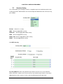
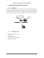
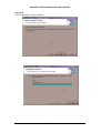
1
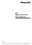
Loop-W8110-BG-500-EANT 2.4 GHz 802.11b/g Outdoor Access Point Repeater - Bridge Professional Turbo Speed - 108 Mbps USER’S MANUAL LOOP TELECOMMUNICATION INTERNATIONAL, INC. 8F, NO. 8, HSIN ANN RD. SCIENCE-BASED INDUSTRIAL PARK HSINCHU, TAIWAN Tel: +886-3-578-7696 Fax: +886-3-578-7695 2010 Loop Telecommunication International, Inc. All rights reserved. Version 5 05 FEB 2010 TABLE OF CONTENTS 1 2 PRODUCT DESCRIPTION ..................................................................................................1 1.1 Description ..............................................................................................................1 1.2 Features ..................................................................................................................2 INSTALLATION...................................................................................................................3 2.1 Component List .......................................................................................................3 2.2 System Requirements for Configuration ...................................................................3 3 CONNECTION.....................................................................................................................4 4 QUICK SETUP GUIDE.........................................................................................................5 5 4.1 Setup Guide ............................................................................................................5 4.2 Mounting Guide .......................................................................................................7 BASIC IP NETWORKING ....................................................................................................8 5.1 IP = Internet Protocol ...............................................................................................8 5.2 Ports........................................................................................................................8 5.3 Static IP Address .....................................................................................................8 5.4 Dynamic IP Address ................................................................................................8 5.5 DHCP (Dynamic Host Configuration Protocol)..........................................................8 5.6 Wireless LAN Basics................................................................................................8 5.7 SSID........................................................................................................................9 5.8 Encryption ...............................................................................................................9 5.9 Channel ...................................................................................................................9 5.10 Signal Strength ........................................................................................................9 5.11 Interference .............................................................................................................9 5.12 Roaming................................................................................................................10 6 GETTING STARTED..........................................................................................................11 7 CONFIGURATION MENU..................................................................................................12 7.1 Administration........................................................................................................13 7.2 Site Survey ............................................................................................................14 7.3 IP Configuration.....................................................................................................14 7.4 Operation Mode.....................................................................................................15 7.5 Statistics................................................................................................................17 7.6 Radio Setting.........................................................................................................18 7.7 Security Setting .....................................................................................................20 7.7.1 WEP Security ........................................................................................................20 7.7.2 WPA-PSK Security ................................................................................................21 7.7.3 WPA Security ........................................................................................................22 7.7.4 WPA2_PSK Security..............................................................................................23 i 8 9 10 7.7.5 WPA2 Security ......................................................................................................23 7.8 MAC Addr Control..................................................................................................25 7.9 Protocol Filter ........................................................................................................26 7.10 SNMP Configuration ..............................................................................................27 7.11 Miscellaneous........................................................................................................28 7.12 QoS Setting ...........................................................................................................29 7.13 System Log ...........................................................................................................29 7.14 System Status .......................................................................................................30 7.15 Association Status .................................................................................................30 7.16 Super User ............................................................................................................31 7.17 Firmware Upgrade .................................................................................................32 7.18 Firmware Version...................................................................................................33 7.19 License Key...........................................................................................................33 VIPER QUICK START INSTALLATION.............................................................................34 8.1 Introduction............................................................................................................34 8.2 PC Requirements ..................................................................................................34 8.3 Installation .............................................................................................................35 VIPER QUICK START USER GUIDE.................................................................................38 9.1 Viper QuickStart Icon .............................................................................................38 9.2 Parameters Display in Utility ..................................................................................38 9.3 Username and Password of Utility..........................................................................39 9.3.1 Making Changes....................................................................................................39 9.3.2 Updating Changes .................................................................................................39 9.4 Pinging the Device.................................................................................................40 DISCLAIMER.....................................................................................................................41 LIST OF FIGURES Figure 1-1 W8110-BG-500 .........................................................................................................1 Figure 2-1 Contents of Package .................................................................................................3 Figure 3-1 Network Connection ..................................................................................................4 ii D Bitte führen Sie das Gerät am Ende seinerLewbensdauer den zue Verfügung stehended Rückgabeund Sammelsystemen zu. GB At the end of the product's useful life, please dispose of it at appropriate collection points provided in your country F Une fois le produit en fin devie, veuillez le déposer dans un point de recyclage approprié. ES Para preservar el medio ambiente, al final dela vida útil de su producto, depositelo en los laguares destinado aello de acuerdo con la legislación vigente. P No final de vida útil do producto, por favor coloque no ponto de recolha apropriado. I Onde tutelare l'ambiente, non buttate l'apparecchio trai i normali rifiuti al termine della sua vita utile, ma portatelo presso i punti do taccolta specifici per questi rifiuti previsti dalla normativa vigente. NL Wij raden u aan het apparant aan het einde van zijn nuttige levensduur, niet bij hey gewone huisafval te deponeren, maar op de dearvoor bestemde adressen. DK Når produktet er udtjent, bor det børtskaffes via de sæ rlige indsamlingssteder i landet. N Ved slutten av produktets levetid bør det avhendes på en kommunal miljøstasjon eller leveres til en elektroforhandler. S Lämna vänligen in produkten på lämplig återvinningsstation när den är förbrukad. FIN Hävitä tuote käytöiän päättyessä viemällä se asianmukaiseen keräyspisteeseen. PL Gdy produkt nie nadaje sie juz do dalszego uzytku, nalezy zostawic go w jednym ze specjalnych punktów zajmujacych sie zbiórka zuzytych producktów w wybranych miejscach na terenie kraju. CZ Po skončení jeho životnosti odložte prosím výrobek na přislušném sbĕrném místé zřízeném dle předpisů ve vaší zemi. SK Po skončení jeho životnosti odovzdajte prosím zariadenie na príslušnom zbernom mieste podía platných miestnych predpisov a noriem. SLO Ko se izdelku izteče življenska doba, ga odnesite na ustrezno zbirno mesto oziroma ga odvrzite v skladu z veljavnimi predpisi. GR Σ τ ο Тέ λ ο ς тη ς λ ε ι τ ο υ ρ γ ι κ ή ς Ζ ω ή ς τ ο υ π ρ ο ϊ ό ν τ ο ς π α ρ α κ α λ ώ Π ε τ ξ τ ε τ ο σ τ α ε ιō ικ ά σ η µ ε ία π ο υ Π α ρ έ χ ο ν τ α ι ο τ η χ ω ρ α σ α ς . PRC , iii CHAPTER 1 PRODUCT DESCRIPTION 1 PRODUCT DESCRIPTION 1.1 Description The product is based on the IEEE 802.11b/g standard, which is the latest 54Mbps Wireless LAN (WLAN) standard. Having this wireless protocols in one product ensure that your investments are protected, while enabling you to enjoy the fastest Wireless LAN speed. This product model – W8110-BG-500 could operate as either one of the following modes: a. Wireless LAN Access Point (AP) mode. b. Wireless Ethernet Bridge mode. c. Repeater mode. Figure 1-1 W8110-BG-500 1 CHAPTER 1 PRODUCT DESCRIPTION 1.2 Features Fully compatible with IEEE 802.11b/g WLAN standard Utilize OFDM (Orthogonal Frequency Division Multiplexing) Wireless data rate of up to 108Mbps. Operates in the 2.4GHz license-free frequency band Industrial grade IP67 Casing Power over UTP cable DC supply WEP (Wired Equivalent Privacy). A simple WLAN encryption standard to protect wireless data from sniffers. WPA (WiFi Protected Access), for AP mode only. An improved WLAN encryption standard where the secret key renew automatically at regular intervals. TKIP (Temporal Key Integrity Protocol). A new encryption key will be generated by corporate RADIUS server when a authorized wireless adaptor/user associate with the Access Point. This encryption key renew automatically at regular intervals. This is normally used in high security enterprise networks. Pre Shared Key (WPA-PSK). A new key is generated each time a wireless adaptor connects to the Access Point. This normally used for home user without a RADIUS server. Remote AP list provides added security for AP mode. Protocol Filters provides security to the network IPX Filter Wireless Isolation. Each wireless user would not be able to see each other even though they are in the same subnet. This is to protect the privacy of each user. Broadcast Filter Multicast Filter User-friendly web-based interface for managing and configuring the Access Point. QoS features for multimedia support - voice, video and audio. Important Note 1) The transmitter module may not be co-located with any other transmitter or antenna. 2) Caution : Antenna installation should be done by experienced antenna installer. 2 CHAPTER 2 INSTALLATION 2 INSTALLATION 2.1 Component List • W8110-BG-500 • 48V combiner adaptor (PoE) • Screws, washers, nuts, U-bolt • Mounting bracket (wall or pole) • 1.5m power cord • Dual band omni antenna • N jack metal cover • Waterproof RJ45 Adaptor Figure 2-1 Contents of Package Note: Standard package may vary with model type and country. Using a combiner adaptor with a power rating other than the one included in the package will cause serious damage to the Access Point and void the warranty for this product. 2.2 System Requirements for Configuration Computers with Windows, Macintosh or Linux-based operating systems and with an Ethernet adaptor Internet Explorer version 5.5 and above or Netscape Navigator that supports Java 3 CHAPTER 3 CONNECTION 3 CONNECTION Network LAN LAN+DC Figure 3-1 Network Connection 4 CHAPTER 4 QUICK SETUP GUIDE 4 QUICK SETUP GUIDE 4.1 Setup Guide Step 1: Set default LAN IP address The default LAN IP address is 192.168.1.20 Step 2: Set password The default login name is admin (in lower case letters), the default password is LOOP (in upper case letters). Step 3 : Configure the AP Step 3.1 : Set IP configuration This page allows you to choose the type of IP address 5 CHAPTER 4 QUICK SETUP GUIDE Step 3.2: Set operation mode This page allows you to set the AP as either an Access Point, a client or a repeater. 6 CHAPTER 4 QUICK SETUP GUIDE Step 4: Set security settings This section allows you to configure wireless encryption to prevent unwelcome parties from reading your traffic. Step 5: Reboot the AP Reboot the system to make all the settings take effect. 4.2 Mounting Guide 7 CHAPTER 5 BASIC IP NETWORKING 5 BASIC IP NETWORKING 5.1 IP = Internet Protocol IP stands for Internet Protocol. In an IP network, every device has a unique IP Address (For example: 192.168.1.35) to identify itself. There are two ways of assigning an IP address to a PC or Router: Static and Automatic (DHCP). Static IP addresses are keyed-in manually, while Dynamic IP’s are distributed by a DHCP Server. 5.2 Ports Every packet of traffic is identified by its Source and Destination Addresses, which would ensure that the packet arrives at the correct destination. A Port Number is also embedded in each packet; to identify which software application that generated and uses that packet. Therefore, if it blocks a certain port number, it denies the particular software from using the connection. 5.3 Static IP Address Static IP addressing ensures that the device will always have the same IP address. Static addressing is commonly used for your servers. 5.4 Dynamic IP Address A dynamic IP address is one that is automatically assigned to a PC. These IP addresses are “dynamic” because they are only temporarily leased to the PC when it connects to the network. This is the most convenient and common way of managing IP addresses in a network. The Server that manages this pool of IP addresses is called the DHCP Server. The product has a DHCP Server built-in to simplify the network management. 5.5 DHCP (Dynamic Host Configuration Protocol) The PC obtaining an IP address from the Server is called the DHCP Client. If there is already a DHCP Server running on your network, you must disable one of the two DHCP servers. Running more than one DHCP server together will cause network problems! 5.6 Wireless LAN Basics A Wireless LAN (WLAN) is a computer network that transmits and receives data with radio signals instead of using cables. WLANs have become common in homes, offices, airports and public Hotspots. WLAN can support the same applications and software that run on a wired network (LAN). Besides supporting the same software and functions, WLAN brings greater convenience and eliminates the need to lay Ethernet cables in a home or office. 8 CHAPTER 5 BASIC IP NETWORKING The AP can even support 108Mbps wireless data rate at Turbo mode. This is only applicable for user using recommended Turbo-capable Cardbus (with Atheros chipset). WLAN networking involves a few additional parameters to be configured: 5.7 SSID The SSID is the “network name” for the WLAN network. The SSID is any name, and can be any set of characters or numbers. The Client sniffs the radio frequencies for an AP with the same SSID with itself. The client locks onto the AP and they are “associated”. To enable plug-and-play convenience, most client cards can sniff the frequencies to extract the available SSIDs to let the user choose from. 5.8 Encryption WLAN traffic can be captured by anybody to be read! The solution is to use encryption to make the traffic appear as random characters to the eavesdropper. Both the AP and client must use the same encryption standard and key to enable them to decode the “rubbish”. If the encryption settings are mismatched, the client and AP cannot associate. WEP (Wired Equivalent Privacy) is the most common WLAN encryption standard. 5.9 Channel There are a total of 13 channels in the 2.4GHz band. Depending on regulation, not all the frequencies may be available in every country. Frequency is configured on the AP only. The client searches for the AP and locks onto that AP’s channel. 5.10 Signal Strength Radio signals drop in power over a distance. Even if all the settings are correct, low signal strength makes association impossible. The usable distance between the AP and client can range from a few meters indoor to a few km. When setting up the client, make sure that you: Keep at a distance between the AP and the clients. Make sure that the WLAN signals do not have to pass through too many concrete walls and metal structures to reach the client. Make sure that client are located far away from one another to avoid interference. Make sure that there is line of sight between the AP and client device. 5.11 Interference Interference happens when 2 clients with the same channels are placed near to one another. The speed of the network drops and the signal strength fluctuates wildly. 9 CHAPTER 5 BASIC IP NETWORKING 5.12 Roaming Association happens when the SSID, Encryption and MAC Address Control settings are correct between the AP and client. If 2 APs with these same settings are located in the same area, the client would choose to associate to the one which gives it a better signal strength. The client would roam over to the 2nd AP when he moves nearer to it. The client switches AP and frequency as he does so. 10 CHAPTER 6 GETTING STARTED 6 GETTING STARTED Connect the network as shown previously. Note: If your PC is wireless, check the PC’s card utility to make sure that the signal strength is good and that the bottom LED lights up on the AP. Open a Web browser (Internet Explorer, Netscape etc.). Type the AP LAN IP (192.168.1.20) address into the browser’s Address field. The default LAN IP address is 192.168.1.20. 11 CHAPTER 7 CONFIGURATION MENU 7 CONFIGURATION MENU In every Web Configuration page, the left panel is the navigation menu containing the main sections. The right-side frame is where the detailed configuration is done. Navigation P ane l C onf igu r ation P ane l 12 CHAPTER 7 CONFIGURATION MENU 7.1 Administration This page allows you to change the Username and Password for admin user/end user. The default username is admin (in lower case letters) and the default password is LOOP (in upper case letters). After every factory reset, the Username and Password reverts to this combination. To view/upgrade firmware version, you need to close this configuration page. Then you have to login as a super user/system administrator in the configuration page again. The default username is super (in lower case letters) and the default password is LOOP (in upper case letters). After every factory reset, the Username and Password reverts to this combination. Refer to super user instructions for more info. The username and password are case sensitive. Remember that after every configurations change, it is necessary to update and reboot the AP for changes to take effect. 13 CHAPTER 7 CONFIGURATION MENU 7.2 Site Survey: 7.3 Site Survey Displays the MAC address, RSSI, SSID and the channel of other AP. IP Configuration This page allows you to choose the type of IP Static IP mode: When you boot up the AP for the first time, it is in Static mode. You assign a Static IP to the AP. The default IP address, subnet mask and gateway mask are 192.168.1.20, 255.255.255.0 and 0.0.0.0. DHCP mode: the AP will obtain an IP Address from an upstream DHCP Server. DHCP Relay: When DHCP relay is enabled, the A-100-IANT18 will transmit packets to another PC. Note: When in DHCP client mode, these 4 columns show the IP settings obtained from the network. 14 CHAPTER 7 CONFIGURATION MENU 7.4 Operation Mode Operation Mode: The AP can be used as an Access Point or as a Wireless Bridge or a repeater. Wireless Bridge or repeater is used when it is not advisable to lay an Ethernet line over a distance. Two AP can be set up to connect over this distance, acting as the wired backbone. SSID: Service Set Identifier. It is a sequence of characters that uniquely names a Wireless LAN. This name allows PCs to connect to the correct Wireless Access Point when multiple Access Points operate in the same location. The default SSID is 11g. Wireless Mode: The AP or Bridge operates in the frequency of 2.4GHz for 802.11b/g/turbo g. Radio Frequency: There are different frequency channels depending on the country of use. You can choose to set the frequency channel to use or use SmartSelect for automatic channel selection. WDS: Enable or disable or disable with multiple PC support. When WDS enabled, the bridge can support multiple PCs behind it. When WDS disabled, the bridge can support only one PC behind it. When disabled with multiple PCs support, the bridge can support multiple PCs behind it, even if the AP cannot support WDS. Advance Settings: This is to set the distance for bridging. The default distance is 4-6km. 15 CHAPTER 7 CONFIGURATION MENU Remote AP MAC List: The Bridge will only associate with AP whose MAC address is in the list. It is essential to type in the MAC address of the AP without any spacing in front or behind it. Antenna Adjust: This is to facilitate the adjustment of antenna for long distance bridging. This page shows the MAC Address and Signal Quality of the units associated to the AP. For long distance bridging, make sure that you get at least a “good” signal quality for desired performance. Do not insert any spacing in front or behind the MAC address when using Remote AP MAC List. Failing to do so will cause the bridge unable to associate with the intended AP. 16 CHAPTER 7 CONFIGURATION MENU 7.5 Statistics The statistics screen displays information on wireless and Ethernet connections. 17 CHAPTER 7 CONFIGURATION MENU 7.6 Radio Setting Data Rate: You can fix the data rate to different values as 11Mbps or 24Mbps. However it is recommended to set the setting to “Best” for the AP to determine the best data rate to be use. Transmit Power: Sometimes, it is useful to decrease the coverage range of each AP, so that more APs can be located together without interference to one another. The default transmission power is 100%. Antenna Diversity: Three options are available. Choose among Best (to use one of the two antenna that works more efficiently), 1 (antenna number 1), or 2 (antenna number 2). Software Tx Retry Times: Specify the number of times that the A-100-IANT18 software resend packets when the transmission fails. Hardware Tx Retry Times: Specify the number of times that the A-100-IANT18 hardware resend packets when the transmission fails. Beacon Interval: Choose between 20 to 1000. Low Beacon Interval will make the association and roaming process very responsive. However, throughput will decrease, so it is necessary to strike a balance. Typical Beacon Interval is set to 100ms. 18 CHAPTER 7 CONFIGURATION MENU Data Beacon Rate (DTIM): Choose between 1 to 255.This is always a multiple of the beacon interval. It determines how often the beacon contains a delivery traffic indication message (DTIM). The DTIM tells power-save client devices that a packet is waiting for them. RTS/CTS Threshold: Enter a value between 0 and 2347. Short Preamble: Enable to use Short Preamble in the Wireless LAN packet headers. Most manufacturers implement long preambles. Even if there is a mismatch between AP and the client, they can still connect well and the mismatch may not be noticeable to most users. Do not change this setting without seeking advice. Protection Mode: Select None, Always or Auto. Protection Rate: Select 1Mbps, 2Mbps, 5.5Mbps or 11Mbps. Protection Type: Select either CTS only or RTS-CTS. Short Slot Time: Enable or disable short time slot usage. Allow 2.4GHz 54Mbps Stations Only: Use this radio button to enable or disable the association of 2.4 GHz 54 Mbps STA only. Multicast to Non-WDS Station: When Disabled mode is selected, only WDS stations can be link. Broadcast to Non-WDS Station: When Disabled mode is selected, only WDS stations can be link. 19 CHAPTER 7 CONFIGURATION MENU 7.7 Security Setting This section allows you to configure wireless encryption to prevent unwelcome parties from reading your traffic. Authentication can also be configured to block outsiders from accessing your network. Disable: WEP: No wireless security. Select to apply WEP security. WPA-PSK: WPA: Select to apply WPA-PSK security. Select to apply WPA security. WPA2_PSK: Select to apply WPA2_PSK security. WPA2: Select to apply WPA2 security. 7.7.1 WEP Security Key Entry Method: Choose Hexadecimal if you want to enter the Keys in hexadecimal format. Otherwise, choose Ascii Text to enter the Key in ASCII format. ASCII is also called Alphanumeric in some systems. Use the same key format for the AP and Client! 20 CHAPTER 7 CONFIGURATION MENU Encryption Key: Enter the encryption key. Key Length: Choose the number of bit for the encryption key. Note: Hexadecimal Characters: 0,1,2,3,4,5,6,7,8,9 and a,b,c,d,e,f ASCII Characters: 0,1,2,……8,9 and a,b,c,d,………x,y,z 7.7.2 WPA-PSK Security PassPhrase: Key in the 8-64 character for PSK. Cipher Type: Choose Auto, TKIP or AES. 21 CHAPTER 7 CONFIGURATION MENU 7.7.3 WPA Security RADIUS Server IP: Enter the IP Address of the RADIUS Server (for 802.1x authentication purposes). This is used only when you have a RADIUS Server and want to use it for authenticating the Wireless Clients. Almost all homes and many offices do not have a RADIUIS Server. These settings are for advanced users only. RADIUS Port: Enter the port number of the RADIUS Server. RADIUS Secret: Enter the Shared Secret of the RADIUS Server. (Only if 802.1x protocol is used) Key Update Interval: Specify the interval in milliseconds. The default is 1800. Cipher Type: Choose Auto, TKIP or AES. 2.4GHz Key Source: Specify the location of the key storage. (Only if 802.1x is used.) If you are using PSK or Pre-shared key, select local. 22 CHAPTER 7 CONFIGURATION MENU 7.7.4 WPA2_PSK Security WPA2_PSK: is the enhancement of WPA-PSK which uses the AES encryption algorithm. 7.7.5 WPA2 Security WPA 2 is the enhancement of WPA which uses the AES encryption algorithm. RADIUS Server IP: This is an individual server used as the radius server for WPA 2 security authentication. Set an ip address for the radius server and enter this ip address in the AP config page. 23 CHAPTER 7 CONFIGURATION MENU RADIUS Server Port: The port of the radius server is set as 1812(default). The port setting can also be changed and follow according to the radius server port setting. Radius Secret: Set the shared secret password for the radius server and enter this password in the AP config page. Key Update Interval: This is the rate at which the radius server managed the re-keying process by changing the secret key for an AP and all stations on a periodic basis. The default is 1800sec. Select a number in between 30sec and 252sec. Cipher Type: You can choose to use TKIP or AES or auto for the encryption or decryption method. 24 CHAPTER 7 CONFIGURATION MENU 7.8 MAC Addr Control This is only use when the AP is operating in the AP mode. MAC Addr Control: Enable or Disable MAC address Control. MAC Address: Enter the MAC address of the client. Allowed MAC Address List: Reflects the MAC address of the clients that are allowed to associate with the AP. 25 CHAPTER 7 CONFIGURATION MENU 7.9 Protocol Filter Filter IPX Packet: Selecting this option will disallow all IPX packets to pass through. Wireless Isolation: Selecting this option will disallow wireless clients associated with this device to communicate with each other. Enable Broadcast Filter: Selecting this option will filter off out broadcast storm. Broadcast Number Allowed: Select a number in between 10 to 200. Enable Multicast Filter: Selecting this option will filter off out multicast storm. Multicast Number Allowed: Select a number in between 10 to 50. Enable Bandwidth (QoS): Selecting this option will limit the bandwidth on TCP/IP data based on the number entered in the textbox. Bandwidth Allowed: Select a number in between 6144 to 7077888 bytes. Enable PPPOE Exclusive: Prevent any data packet transmitting except PPPOE. 26 CHAPTER 7 CONFIGURATION MENU 7.10 Enable SNMP: SNMP Configuration Selecting this option will enable the SNMP feature. Read Community String: The SNMP Client with this “passphrase” will have “Read” access. Write Community String: The SNMP Client with this “passphrase” will have “Write” access. System Contact: To set the MIB2 sysContact OID value. System Location: To set the MIB2 sysLocation OID value. Trap Receiver IP Address: Fill in the IP address of the network management system. The A-100-IANT18 allows for four network management systems. Rssi Too Low Threshold: RSSI (Received Signal Strength Indication) is a measurement of the strength of a received radio signal, measured in dBm. An alarm will be issued when a received signal is lower than this threshold. Rssi Too High Threshold: RSSI (Received Signal Strength Indication) is a measurement of the strength of a received radio signal, measured in dBm. An alarm will be issued when a received signal is higher than this threshold. 27 CHAPTER 7 CONFIGURATION MENU 7.11 Miscellaneous Enable Telnet: Disable/enable Telnet access to this device. Enable monitoring IP: This function allows the user to monitor another device. First check the Enable monitoring IP, then enter the IP address of the device you want to monitor and specify the Failure Criteria and Ping interval. Save configuration to local device: After you have successfully configured the AP, you can save this “Good Config” into device memory. Restore configuration from local device: You can retrieve this “Good Config”, if you have messed up some settings and do not know what was the previous working setting. Revert to factory setting: If you have even forgotten the password to get into the configuration pages, you would have to do a Factory Reset to the AP. Save configuration to local PC: After successfully configured the AP, save this “Good Config” into the computer system. Configuration file on local PC: Browse to the location of the saved “Good Config” in the computer system. Restore configuration from local PC: Allow restoring back to the “Good Config” from the computer system. 28 CHAPTER 7 CONFIGURATION MENU 7.12 QoS Setting QoS Setting: Enabling QoS setting will give u a better Video/VOIP signal quality. 7.13 System Log Enable Remote System Log: This will enable all log records to be saved into another server for future reference. Server IP: Key in the specific IP to store the System Log. Server Port: Select a specific port to store the Log Entries. Enable Local System Log: Tick to enable Record Logging When Log is Full: Stop Logging: Prevent future data log. Auto Delete: Clear log page after 200 Entries. 29 CHAPTER 7 CONFIGURATION MENU 7.14 System Status This page presents a convenient overview of the overall status of the AP. The most common configuration parameters are shown here, for a quick look. 7.15 Association Status This page presents an overview of the MAC address and Signal Strength of all clients connected to the AP through Ethernet or wireless. The signal strength is the Signal to Noise ratio (SNR) and it is measured in dBm. 30 CHAPTER 7 CONFIGURATION MENU 7.16 Super User This page allows you to change the Username and Password for admin user/end user. The default username is super (in lower case letters) and password is LOOP (in upper case letters). After every factory reset, the Username and Password reverts to this combination. The AP does not allow you to set the same Username for both admin and super users. The Username of super user cannot be the same as the Username of admin user. 31 CHAPTER 7 CONFIGURATION MENU 7.17 Firmware Upgrade This page allows you to update the firmware (software) in the AP. New firmwares are issued to improve the performance and add features to the product. The new firmware will be name “apimg1”. 1. Save the file in your PC. 2. Browse to the file with the name “apimg1”. 3. Click on Upload. 4. Reboot the AP and the process is complete. 5. After reboot perform a default factory setting. Do not change the filename of the new firmware. New firmware with filename other than “apimg1” will cause the process to fail. 32 CHAPTER 7 CONFIGURATION MENU 7.18 Firmware Version This page presents information of the firmware version of the AP. 7.19 License Key This page allows you to key in the license key to enable your request for additional features requirements. The license key can be obtained from our company at a certain fees and features request agreement. 33 CHPATER 8 VIPER QUICK START INSTALLATION 8 VIPER QUICK START INSTALLATION 8.1 Introduction The Viper QuickStart (QS) Version 1 Beta4 utility is an easy-to-use software that allows an Administrator to quickly configure the AP at first boot-up. The QS Utility only communicates with authorized Access Points and Bridge. The Utility allows the devices to be monitored and configured even if they all have the same default IP Address at first boot-up after installation. W A N/ I nte r ne t AP Wireless Client 8.2 PC Requirements • X86 based CPU, 600Mhz & above • 128 MB RAM • 1.5 MB hard disk space • Ethernet port / Wireless LAN adapter • Windows 2000 and above 34 Q S P C CHPATER 8 VIPER QUICK START INSTALLATION 8.3 Installation Step One Double click on the file setup.exe and click Next to continue. Step Two Click Next to accept the default installation directory. If you wish to change the installation directory, click on the Change button to select a new directory. 35 CHPATER 8 VIPER QUICK START INSTALLATION Step Three Click Install to do the actual installation 36 CHPATER 8 VIPER QUICK START INSTALLATION Step Four Click Finish to exit the installation wizard. 37 CHAPTER 9 VIPER QUICK START USER GUIDE 9 VIPER QUICK START USER GUIDE 9.1 Viper QuickStart Icon Click on the desktop icon 9.2 to start the application. Parameters Display in Utility The Utility displays the following parameters that can be changed. IP Address Subnet Mask Gateway Device Name Channel DHCP/Static IP 38 CHAPTER 9 VIPER QUICK START USER GUIDE 9.3 Username and Password of Utility If the username/password of the Devices have been changed, the QS Utility has to be updated with the correct username and password. If the username/password of the QS Utility and the Device is different, QS Utility will not operate as desire. 9.3.1 Making Changes The changes are directly applied in the Utility. It does not matter if all the devices have the same IP Address. The QS Utility identifies them uniquely by their MAC Addresses. 9.3.2 Updating Changes After the necessary changes have been made, the Administrator can apply the changes to the AP. Check on the Reboot Checkbox and click on the Update button to reboot the device. Multiple devices can be updated all at once. Use ctrl-left click to select multiple entries or type ctrl-A to select all entries. Click on Update button to begin the update process. To refresh the view, use the Find button. 39 CHAPTER 9 VIPER QUICK START USER GUIDE 9.4 Pinging the Device The QS Utility can also be used to ping a selected Device to check the connectivity. 40 CHAPTER 10 DISCLAIMER 10 DISCLAIMER Manufacturer assumes no responsibility for any damage or loss resulting from the use of this manual. Manufacturer assumes no responsibility for any loss or claims by third parties that may arise through the use of this product. Manufacturer assumes no responsibility for any damage or loss caused by incorrect use of the AP. The contents of this manual are subject to change without prior notice due to engineering improvement. No part of this manual may be reproduced in any form without the express written consent of the Manufacturer. Sample displays shown in this Manual may differ somewhat from the displays actually produced by the product. User Manual may differ for different firmware version. All brands and product names are trademarks or registered trademarks of their respective holders. 41