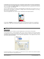
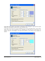
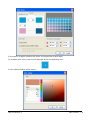
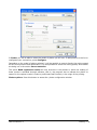
1
User’s manual
SOFTWARE FOR
COLOR PRINTING
SEPARATIONS PRINTING
RAPPORT PRINTING
Rev. 5.5.30
Table of contents
1.
Introduction .........................................................................................5
Welcome to the program ....................................................................................................5
What is the program? ........................................................................................................5
• FILM (only for film printing)...........................................................................................5
• RIP (only for color printing). ..........................................................................................5
⇒
Rapport (only for continuous printing). .........................................................................5
2.
Installation of the program ..................................................................7
System Requirements ........................................................................................................7
Installation .......................................................................................................................7
Program protection ............................................................................................................7
Selection of the printer.......................................................................................................7
•
Output color profiles for color printing .............................................................................9
3.
General functions ............................................................................... 11
Main Window .................................................................................................................. 11
Viewing modes................................................................................................................ 13
Color simulation .............................................................................................................. 13
Control Center ................................................................................................................ 14
Guidelines ...................................................................................................................... 14
Measurement units .......................................................................................................... 16
4.
Design edition .................................................................................... 18
Loading designs .............................................................................................................. 18
•
Charging designs in the FILM mode .............................................................................. 18
Charging designs selecting FILM or RIP............................................................................... 18
Sizes and position ........................................................................................................... 18
•
The link between separations of a design....................................................................... 20
Duplicate graphically........................................................................................................ 21
•
Cropping................................................................................................................... 21
Automatic distribution ...................................................................................................... 23
•
Tiling ....................................................................................................................... 24
Mosaics.......................................................................................................................... 26
•
Montages in FILM mode .............................................................................................. 29
Crop & Registration Marks ................................................................................................ 30
5.
Printing .............................................................................................. 31
General Options .............................................................................................................. 31
Page & Copies options...................................................................................................... 32
Print and Cut .................................................................................................................. 33
6.
Job Manager ....................................................................................... 35
7.
Preferences ........................................................................................ 37
User's manual 5.5
Introduction • 2
Edit ............................................................................................................................... 37
Color management .......................................................................................................... 37
Performance ................................................................................................................... 38
8.
Interface customization ..................................................................... 40
Dialog for selecting options. .............................................................................................. 40
Automatic positioning of floating windows ........................................................................... 42
Windows that hide automatically ....................................................................................... 43
9.
File Browser ....................................................................................... 44
10. Connectivity ....................................................................................... 46
Problems........................................................................................................................ 46
Connector Types ............................................................................................................. 46
11. Separation creations .......................................................................... 48
•
•
•
•
•
•
•
•
•
•
Initial considerations .................................................................................................. 48
Preparing the design for printing .................................................................................. 48
The overprints ........................................................................................................... 49
Multi-channel images.................................................................................................. 49
The separation options dialog. ..................................................................................... 50
Linearisation of the black ink. ...................................................................................... 51
Register and Crop marks............................................................................................. 52
Channel Selection ...................................................................................................... 52
Dither type ............................................................................................................... 52
Edition of an executed separation................................................................................. 54
12. Film printing setup ............................................................................. 56
•
Print ........................................................................................................................ 56
Media Size...................................................................................................................... 57
•
Ink control ................................................................................................................ 58
Advanced ....................................................................................................................... 59
13. Color Control ...................................................................................... 63
Introduction ................................................................................................................... 63
Input ICC profiles ............................................................................................................ 63
Proofing ......................................................................................................................... 64
Brightness and contrast settings ........................................................................................ 64
Using Multichannel DCS files. ............................................................................................ 65
Special colors.................................................................................................................. 67
Generation of color palettes .............................................................................................. 72
14. Cutting ............................................................................................... 76
Introduction ................................................................................................................... 76
15. Configuring the printer ....................................................................... 82
Print Control ................................................................................................................... 82
Dither method ................................................................................................................ 84
User's manual 5.5
Introduction • 3
Media Size...................................................................................................................... 86
Ink control ..................................................................................................................... 88
Color Control .................................................................................................................. 89
Output ICC profile ........................................................................................................... 91
Rendering Intents............................................................................................................ 91
Advanced ....................................................................................................................... 93
16. Tutorial............................................................................................... 96
Starting the program. ...................................................................................................... 96
Loading a design. ............................................................................................................ 96
Size and position ............................................................................................................. 96
Input profiles. ................................................................................................................. 97
Render intents. ............................................................................................................... 98
Media Size...................................................................................................................... 99
Printing parameters. ........................................................................................................ 99
Printing........................................................................................................................ 102
Results correction.......................................................................................................... 103
17. Program for the calculation of printing consumption........................ 105
Program configuration.................................................................................................... 105
Consumption results ...................................................................................................... 109
18. Rapport ............................................................................................ 112
⇒
⇒
⇒
Continuous rapport mode printing ........................................................................... 112
Opening a document for Rapport. ............................................................................ 112
Composition Options.............................................................................................. 113
User's manual 5.5
Introduction • 4
1. Introduction
The manufacturer reserves the right to modify the contents of this document without prior
warning.
The software described herein is the property of the manufacturer., for the exclusive use of the
registered users. The total or partial reproduction of the program is prohibited, as is that of its
manuals, by electronic, mechanical, photographic or any other means, without the express written
authorization of the manufacturer.
Welcome to the program
Welcome to the program. These RIP software offer you precision printing of all types of color
images. It include a PostScript interpreter for importing, and color models and drivers for most
digital color printers.
This manual assumes you understand the basics of Windows, such as using mouse, clicking,
choosing menu items, opening, saving and closing files, etc. If you are not familiar with these or
other basic techniques, see your Windows manual.
What is the program?
This program is an image processor program to print large format (RIP) and / or for the creation
of separations in film printing and / or for continuous Rapport printing.
This program can be achieved with three levels of features:
FILM EDITION: Only for the film printing and it doesn’t permit color printing.
FILM & RIP EDITION: For film printing and color printing.
RAPPORT EDITION: For continuous printing (Rapport).
This manual covers all program levels. Look at the chapters that below to your licensed program.
The exclusive sections for each level are indicated with the following initial mark:
FILM (only for film printing).
RIP (only for color printing).
⇒
Rapport (only for continuous printing).
With the program we can import any design in PostScript® format or any other image coming
from scanner or other programs and scale these designs to the necessary measurements.
The program achieves the enlargement of the image with maximum quality and thanks to its color
correction algorithms and the different shades available it will create a perfect result ready to send
to printers and/or cutting machines in large format. If necessary, colorimeter data can also be
User's manual 5.5
Introduction • 5
entered in order to calibrate the colors of new supports and inks. The use of ICC printer
characterization profiles is also possible.
It is also possible to tile the design if this exceeds the measurements of the printer or plotter.
User's manual 5.5
Introduction • 6
2. Installation of the program
System Requirements
An IBM PC or compatible computer is required with a Pentium® or superior type processor, with
the environment Microsoft Windows® 2000, XP or superior installed.
It is advisable that the computer has 512Mb or more of RAM memory and a hard disk of 80Gb or
more and Microsoft Windows® XP.
Installation
Introduce the original CD-ROM of the program into your unit and follow the instructions which will
appear on the screen. If the installation does not start up automatically it is because the
automatic reproduction of the CD-ROM in your system is not activated when this is inserted.
Consult Window’s Help to activate this function.
In case the program requires a license file (cibercat.lic), this is to be found in the root of the CD
with a number and the extension "lic" (similar to 1234567.lic), and it should be selected as it is
the one which corresponds to your program.
Program protection
The program comes with a USB protection key which limits the use of the PC to which it is
connected.
Place the USB protection in a USB port.
Selection of the printer
First of all select the printers you wish to use with the program, the connection type and other
advanced parameters.
In the main window, click the Configure button to access the printer configuration window.
User's manual 5.5
Installation of the program • 7
The Add and Remove buttons allow you to introduce the printers you require in the list of
installed printers.
You can configure the type of connection used for each printer. To do this, select the required
printer from the list and then select the required type of connection in the Connection section:
Refer to the connections section to find out more about the various possibilities the program gives
you.
If you have various printers in the program, one of them will be the default printer. This is the one
that will always be used when the program is started and when a new document is opened. To set
the default printer, place the mouse on the required printer, click the right-hand button of the
mouse and select the option from the related menu that appears.
A non default printer can also be selected for a specific document. To select a printer from the list,
double-click on the printer and a sign will appear on the left to indicate that this printer will be
selected for the current document.
User's manual 5.5
Installation of the program • 8
Output color profiles for color printing
Once the printer or printers required for the program have been selected, we must add the
outgoing color parameters (of the materials) that you intend to use with each printer.
The program allows two types of file profiles:
1) Standard ICC Color Profiles: This is the ICC file that contains each material's color
information. Normally these are standard files available to the manufacturer, or special programs
can be created.
2) Color Schemes (cps): This is the ICC color profile including all the print parameter and
linearization configuration, i.e. the color scheme includes the configuration of all the print file
options.
Although this step can be carried out at any time, even as new materials are being used, we
recommend installing the most basic ones at the time of installing the program.
Whenever you have a printing scheme and a color profile we recommend installing the printing
scheme because it contains the color profile, the density curves and all the resolution parameters
and the adequate ink limit.
Installing ICC Profiles:
Select the Print control, Color Control branch in the Control Center to access the section for
selecting and loading the parameters.
To install the parameters, click the Add button and a window will appear in which you can select
the directory where the profiles are found.
Click the Ok button and a new window will unfold with a list of all the profiles compatible with the
process you have selected.
User's manual 5.5
Installation of the program • 9
Select the ones you require and click the Ok button. Bear in mind that the program will only show
the parameters which are compatible depending on the type of process selected (CMYK,
CMYKOrGr, etc.)
When selecting the parameters for printing, it is important that the printing resolution coincides as
far as possible with the resolution used to create the ICC parameters, which is normally specified
in the color parameter description.
Installing printing schemes:
To install print schemes in the program (files with cps extension), select the Control Panel Print
Control dialog and click the Add button.
You will see that upon selecting a print scheme all the options from the Printers dialog are
configured along with the corresponding ICC color profile and the linearization file (lut).
User's manual 5.5
Installation of the program • 10
3. General functions
Main Window
When the program is started, the main program window appears.
This is a standard Windows screen with the standard menu bar and buttons to access the main
functions. It also has the action buttons bar and the zoom bar shown on the lower part of the
window. Remember that all bars can be re-positioned.
In the center of the window, you can see the work area where all the designs will be placed. Just
to the right of it you will see the Control Center, from where the majority of transformations and
configurations will be carried out.
At the bottom of the work area a drop-down will be displayed which enables you to work with
three display modes: Scheme, Fast bitmap and Real image.
User's manual 5.5
General functions • 11
The RIP button is for sending the design to the printer. The information bar, situated in the
lowest part of the window, will systematically show you the messages related to the work you are
carrying out or which is currently selected.
Zoom options
In the main window, you can see the zoom buttons bar, used to increase or reduce the size of the
objects on the screen.
The buttons, in this order, carry out the following actions:
The Zoom in tool: This is used to enlarge any area of the design.
The Zoom out tool: This is used to reduce any area of the design.
The Previous Zoom tool: This is used to return to the previous view after having enlarged or
reduced.
The Zoom all tool: Using this you can see all the objects of the design at their largest possible
size, whilst allowing them all to fit into the screen.
The Zoom selected objects tool: This is used to enlarge the objects which have been selected to
the maximum, so that they may be viewed as large as possible in the working area.
The Zoom roll width tool: This is used to view the whole bobbin width on the screen.
The Zoom printer width tool: This is used to view on the screen the whole width of the cut
available in the printer.
Page Orientation
If you are using a bobbin format for printing, this is shown along the width of the program’s work
area, that is to say, the start of the bobbin appears on the right-hand side of the screen, the width
of the bobbin is the vertical part of the screen, and the length of the bobbin is shown towards the
left-hand side of the screen.
In the previous image we can see a design placed lengthwise on the bobbin and at the beginning
of it. So, when we print this design, it will start printing at the beginning of the bobbin, and the
whole length of the image will be printed over the length of the bobbin.
User's manual 5.5
General functions • 12
Viewing modes
The program allows you to view the design in the work area in three different ways, without it
affecting the final quality of the print. These are:
Scheme
The scheme mode only shows a gray rectangle with the size of each design and information on
the name of the document inside the box.
The great advantage of this viewing system is that the screen presentation is immediate and
allows you to work very quickly in making the design composition.
Fast Bitmap
With the fast bitmap mode, a low resolution image is used for each design. This image is only for
a quick viewing of the design and does not have the original quality of the design.
Real Image
With the Real Image mode, the real design resolution is used. In the case of vectorial designs, an
interpretation of the design is made which is shown on the screen with the real quality of the
design.
This the most exact viewing system, but also the most slow.
Color simulation
Color simulation allows you to see the designs with colors nearing the final result you will obtain.
The options are:
Without color preview
With this option, no color simulation will be carried out on the screen, and the designs will be
shown just they open up. These colors will not be modified on screen even if adjustments are
carried out later.
User's manual 5.5
General functions • 13
Simulate document colors
The designs are presented with their original colors, but can be modified by the changes we make
in the program (such as image control, color parameters, etc.).
Simulate printed colors
This mode simulates the colors which will be obtained in the printer. This will depend on the color
parameters selected and on the monitor calibration used.
Control Center
The Control Center is a dialog box, which is used to control most of the functions that the program
carries out along with its configurations.
The operation tree appears at the top of the Control Center. These functions appear and
disappear, depending on the objects selected and the possible actions to be undertaken at each
moment.
There are functions that appear within a main section and are shown as branches of the main
section. Thus, for example, the branches for Input ICC Profiles, Cropping, etc. appear in the
Selection section.
Fold
Unfold
When a main section has branches which are not shown, a
sign appears in front of it. To display
sign, which will then convert to a
sign. To hide
all the branches, use the mouse to click the
the branches click the – sign.
In many of the boxes where the numerical values are introduced, the Enter button must be
pressed to validate the entry and carry out the modification.
In some of the options of the Control Center branches, the button for saving the parameters
introduced is available so that the same configuration is always applied. Obviously, it will always
be possible to change the values manually for each specific case.
Many of the actions that are carried out from the Control Center require the use of the
apply Button. When a value is modified manually, or a transformation has to be applied, these
changes must be effected by clicking this button.
Guidelines
The guidelines are lines that can be placed in any position in the design, as many as are required.
To create guidelines whether they are horizontal or vertical, click the design rulers, and drag the
cursor to the desired position.
User's manual 5.5
General functions • 14
Click the lateral design ruler
Drag to the desired position
To delete a guide, select and drag it out of the working screen.
When an object comes close to a guide line, and if the adjust to guide lines option is activated,
this object will attach itself to the guide line close to it.
The guide lines are especially useful to align various designs on the same horizontal or vertical
line.
Contextual menu in the ruler bar
You access this menu by clicking the right hand button of the mouse over the ruler bar. There are
4 options related to the guide lines:
Activate Guidelines: Allows you to activate the guide lines’ magnetism.
Deactivate Guidelines: De-activates the magnetism of all the guide lines.
Remove all: Eliminates all the guide lines from the design.
Adjust: Activates the guide line adjustment dialog.
Dialog for controlling guide lines
This dialog allows you to create, move or delete the guide lines at will.
User's manual 5.5
General functions • 15
To modify the position of a guide line, click over the value of the position and introduce the new
value.
To add horizontal or vertical guide lines, click the button for adding guidelines and introduce the
position directly in the list of guide lines.
Click the button:
and introduce the value:
To eliminate any guide line from the list, select it and press the Del button on the keyboard.
The Snap to guidelines option activates or de-activates their magnetism. That is to say, if this
option is activated when moving objects, these will tend to attach themselves to the guide line.
Measurement units
The program can be configured to show the objects’ measurement values in measurement units
(in inches by default) through the related menu that appears clicking the mouse’s right-hand
button on the rulers.
The measurement units can also be configured independently for each one of the controls where
numerical values of measurements are introduced.
User's manual 5.5
General functions • 16
User's manual 5.5
General functions • 17
4. Design edition
Loading designs
The program allows you to load various designs in the same work area.
If no design is open in the program, use the program’s Open command or click the open design
button:
If you wish to add a new design in the work area, use the Add design command or click the add
design button:
If you wish to make a copy of a design in the work area, select the option from the Edit menu.
You can also do this by moving the design with the “Ctrl.” Key pressed down.
If you wish to eliminate a design, first select it and then press the “Del.” key on the keyboard or
select the option from the Edit menu.
Charging designs in the FILM mode
When you open a design, the window with the option to configure the parameters will
automatically appear to create a separation. Consult the chapter “creation of separations” to
configurate the parameters.
Charging designs selecting FILM or RIP
If you have the program with the option of color printing at your disposal, when opening a design
you should select if you wish to open the design for color printing or to create separations.
In the inferior part of the window opening files appears the option “Open as”: which permits to
select the objective of the design.
Sizes and position
When you click on a design, it will appear surrounded by 8 marks. These are called Handles . In
this case we can say that the design is selected and we can act upon it. If we wish to select
various designs at the same time, click on them one after the other maintaining the “ctrl.” key
pressed down, or forming a selection window, forming a rectangle so that all the designs which
are completely in it become selected.
User's manual 5.5
Design edition • 18
Selection window for selecting the two above designs
Using the handles you can re-size the designs graphically.
By clicking on and dragging the handles from the ends you modify proportionally the
measurements of the design. That is to say, maintaining its height/width proportions. By clicking
on the central handles from any side, the original proportion will be lost.
Movement is achieved by clicking and dragging within the design.
All these actions can also be carried out numerically through the controls located just on top of
the window.
You can introduce the sizes wanted for the design or the scale factor by using the top controls.
To maintain the proportions, the proportional button must be clicked:
The proportions are maintained (horizontal – vertical).
User's manual 5.5
Design edition • 19
The proportions are not maintained (it will be deformed).
This button will send the chosen design to coordinates 0,0 (source) of the work area
automatically making it unnecessary to establish the x,y position manually.
You can also rotate the design clicking the rotation buttons:
The Mirror option will make a vertical symmetry of the design. That is to say, as if seen reflected
in a mirror placed at one of its sides.
You can also set the design position introducing the sizes in the corresponding section. Remember
that the design position refers to the design’s lower left-hand corner.
While designs are being moved within the work area, the program takes into account all the other
designs that may be there and, if the function from the preferences is activated, the designs will
not overlap.
The link between separations of a design.
All the created separations which belong to the same design are linked with one another, so that
any change we may make in any of these will automatically be applied to the rest of the
separations of the same design.
In this way, for example, when resizing one of the separations automatically the others will be
resized in the same proportion.
Separation of a design
User's manual 5.5
Resizing a separation
Design edition • 20
All the separations resized
Duplicate graphically
Any design which is selected can be duplicated simply by moving it with the “Control” key pressed
down. On releasing the mouse button, a copy of the selected design will appear.
Cropping
This program function allows you to select a specific area of a design and trim it. This is especially
useful for carrying out printing tests on the most representative areas of a design without having
to print the whole design. To do this, select the branch Cropping in the Control Center.
User's manual 5.5
Design edition • 21
The co-ordinates for the cut out rectangle can be introduced numerically or the area can be
selected directly in the design. To cut out on the screen click on one of the corners of the area you
wish to cut out and drag to the opposite corner. The cut out rectangle will be formed. On releasing
the button, only the selected area will be visible, while the remaining area will be gridded.
This operation can be carried out as many times as may be required. The area can also be
modified by moving the corners of the rectangle.
If you have to view again the whole image, click the Reset button. The design cut out function
can also be de-activated de-selecting the Activate cropping option.
The cut out will have been done when you leave the cut out function. In any case, the cut out
area can be modified whenever required.
User's manual 5.5
Design edition • 22
Automatic distribution
The program has a powerful design distribution tool to place the designs on the page, wasting the
minimum material possible and, consequently, also printing them in the least possible time.
Can be accessed clicking the auto-distribution button:
If you do not wish to distribute all the designs which are in the work area, you must select only
those you wish to distribute and select the option for distributing only the selected designs. By deactivating this option all the designs will be distributed.
The ignore non-selected designs option means that when distribution is carried out, the selected
objects can overlap those not selected.
The Minimal separation… is the distance left between designs to avoid overlapping.
To carry out auto-distribution, click the Ok button.
In the following images, you can see the designs without distribution and once they have been
distributed:
Without distribution
Distributed
Distribution in page mode
When the material to be printed on consists of loose leaves the program will distribute the
documents on each page without splitting the designs, except in the case of those that are larger
than the size of the page.
User's manual 5.5
Design edition • 23
Without distribution
Distributed on leaves
Distribution in the film mode
The automatic distribution in FILM mode does not permit to rotate the designs to save the
material since all the color separations belonging to a design have to be printed in the same
orientation, in the contrary it could not register the colors.
Tiling
The program contains a tool for dividing a design into various panels for printing separately. This
option is very useful when the designs are large and must be printed in sections, either for
manual displays or for ease of placement.
To use it click the tiling button.
A new window will appear showing all the panel features available.
User's manual 5.5
Design edition • 24
It is possible to define the lines that mark the separation of the panels, horizontally as well as
vertically.
In the rows and columns sections it is possible to introduce the number of horizontal and vertical
design divisions. The program will distribute the number of divisions equally between each row
and column.
In order to create a new line, place the cursor on one of the angles, superior or lateral, pressing
and dragging until the line is in the required position.
We can place as many dividing lines, horizontal or vertical, as we wish. It is possible to move
graphically their position by pressing the cursor on them or establishing the exact position on the
lists of rows and columns that are shown to the right of this window.
The option overlap allows the generation of an overprint between the panels by which they will
place themselves one on the top of the other in the distance specified in order to facilitate their
ensambling.
User's manual 5.5
Design edition • 25
In the following illustrations both the original design and the panelled result can be observed:
Mosaics
With this option we have the possibility of making multiple copies of a same design with absolute
ease.
Introduce directly the number of rows (across the width of the material) and the number of
columns (along the length of the spool).
To modify these values the total of pieces to be printed will be shown, and in the preliminary
presentation window we will be able to see the final result of the composition
The total number of pieces can be modified in order to make the necessary quantity and save ink
on the printing of unnecessary copies. Enter the exact amount in Total pieces and press the
button next to it.
User's manual 5.5
Design edition • 26
The program will distribute all the asked copies by making the best use of the width of the paper.
Vertical / Horizontal distance: In this section a distance between the copies which are going to
be made can be introduced. We can set independently both the vertical and horizontal distances.
Once the required parameters have been introduced, click “Enter” to validate the data and make
the copies.
Set the copies graphically:
Once the parameters of the auto-repetitions have been set, the number of copies can also be set
graphically. Click on the side handles, as if to stretch the design. When the side handle has been
moved sufficiently, the previews of new copies of the design will appear.
If we release the button at that moment, the new copies will be generated.
NOTE: With regard to the manipulation of the design, all the auto-repetition copies will be
manipulated as if they were a single design. Even if an auto-distribution is done, the autorepetition will consider the whole area/surface as one design only. If the auto-distribution has to
be undone, it will be necessary to select the auto-repetition window again and de-activate the
function.
Labels and self-numeration:
The Edit button opens the window that configures the parameters and allows all the copies
printed to have a different text which can be increased with an established value.
The following window will be shown:
User's manual 5.5
Design edition • 27
First press on design to indicate where to introduce the text that will be automatically modified.
In Alignment the collocation of the new text can be determined with respect to the point chosen
in the design.
The Format is the kind of numeration that will be used, that is, whether they are consecutive
numbers, letters or roman numerals:
The result will be as follows:
User's manual 5.5
Design edition • 28
Montages in FILM mode
The main difference is that all the separations belonging to the same design are related and that
is why the montage we make to one of the separations will be automatically applied to the rest of
the separations of the same design.
Separations of a design
Montage of a separation
Separations with the montage executed on all the channels
User's manual 5.5
Design edition • 29
Crop & Registration Marks
This section allows you to activate the printing of register marks and cutting marks.
The register marks are normally used to match different colors and the crop marks are used as
reference to indicate where the design has to be cut.
The crop marks’ bleeding is in case you wish the cut to be done within the design to be printed or
outside it and not just at the limits. A positive margin displaces the crop lines towards the inside
of the design and would indicate that cropping should be done by a printed zone.
This design has an inside bleeding of the crop marks.
We can also control the thickness of the marks which are printed in case we want them to be
more visible so as to use them more easily.
This same window contains the Print document name option next to the design. The name and
extension of the printed file will appear in the bottom left-hand corner.
There are special register marks designed to be recognized by certain cutting plotters so they can
adjust what has been printed to what needs to be cut (known as OPOS). If your plotter supports
it, consult in the instructions the kind of marks you need to use.
User's manual 5.5
Design edition • 30
5. Printing
General Options
On selection of the RIP button from the program access is given to the configuration window for
the printing options.
Mode
Description
Process and send This means that at the same time that the file is being
simultaneously
processed, the
information that has already been
processed is being sent to the printer. This method is the
one which makes the printing start more quickly, since
when little data has been processed, this has already
been sent. The inconvenient aspect of this system is that
if the computer is not fast enough or the file to be
processed is excessively complex it can happen that the
printer stops to wait for new lines to print. In this case,
and with certain materials, small bands can appear in the
print as a consequence of the ink drying between bands.
Process then send
User's manual 5.5
This means that the program will process the whole file,
and when it finishes it will send all the information to the
printer. This method ensures that all the subsequent
information arrives at the printer without interruptions,
since it is not necessary to make any calculation at the
Printing • 31
moment of printing. What is inconvenient is that in order
to remove a job you need to add together the processing
and printing times. Working in this way can generate
printing files that are too big, and therefore we
recommend checking the free space on the disk.
Process only
In this case, the program will only process the file
generating print directories to be later sent to the device.
If this option is chosen, the program will ask for a file
name and a location on disk before starting the process.
In the first two options we can generate a printing file at the same time as the job is being
processed. This is achieved by selecting the Keep output file option.
The advantage of generating a printing file is that several copies of the same job can be made
without the need for additional processing.
In the case of the print occupying more than one page a printing file is generated for us for each
one of them, adding a number to the original name.
Normally the printer files usually have the extension .pro or .pl. Thus, for example, from a file
named mar.tif a printing file mar.prn can de generated, or in the case of it occupying more than
one page we would produce files like mar_1.prn, mar_2.prn, ...
Take into account that a printing file can need a lot of space on the hard disk, and therefore we
will have to ensure that we have enough space in the unit. As a reference, printing an image of
DIN AO size in a printer of 360 dpi assumes a printing file of some 90 Mb.
Later you can send this file directly to the device with hardly any use of the computer. For that,
use the program queue.
The Start job queue if it is stopped option makes the job queue start up and immediately begin
processing or sending.
The option Keep the job after processed temporarily saves the processed work, in case you
have to re-send the same work again for other copies. Once the work has been erased or the job
queue ended, the work already processed will disappear.
For printers which supply status information, the Check printer status before sending option
allows the program to wait for the printer to be ready to receive information and the program
notifies if there is any problem with the printer. Only some specific connection types and printers
allow for printer status information to be supplied, this is generally the case with printers
connected through network cables (TCP/IP).
The option Enhance printing of shades is an internal function of the program which avoids the
banding effect when smooth gradients of image are printed, creating color changes in a
completely progressive way. We recommend its activation when the design contains gradients of
image to print, but not when it does not, since the processing time of tasks is longer.
The Print only the selected object option will print only those designs which are selected at this
point in time, and will ignore those which have not been selected.
Page & Copies options
The Page & Copies can be found in the second tab of the options window and can be activated,
along with these following options:
User's manual 5.5
Printing • 32
In the box Number of copies one can specify the number of times that the same work will be
automatically repeated, without having to produce the copies manually.
If there are several pages to print you can choose to process every page, or only those that are
selected.
The option Pause between copies generates a pause of a few seconds before sending the
following copies. In certain printers, when sending several copies, the printer loses data or a
transmission error appears, and this can be avoided by establishing this value in a few seconds
(for instance 5 or 10).
Print and Cut
The third tab of the printing options window corresponds to the printing options for those printers
that allow simultaneous printing and cutting.
User's manual 5.5
Printing • 33
Although it is more common to do the printing and the cutting straight after, we may also be
interested in carrying this out in two separate stages. Thus, for example, if we have to laminate a
design first, it will do the printing and then, once laminated, will reintroduce the laminated print
into the plotter in order to cut out the outline.
The options for activating or deactivating printing and cutting are found in this window. If the
cutting option is activated we can adjust the settings of the plotter in cutting mode such as speed,
cutting quality, pressure and acceleration (these last two if the plotter allows it).
There are two sections in Printing and cut size adjust that allow to correct small
maladjustments between what is printed and what is crop, due generally to maladjustments of the
printer. It is possible to find a correction value that will allow the adjustment of the printing and
cropping.
Export paths:
All the cropping paths created can be exported to be crop with the CiberCut software, special for
the vinyl cutting.
Pressing the button Export paths the file selection window will be shown and it will allow you to
enter a file noun and select where to save it.
The generated file has the extension "ct5" and it is only valid to be loaded in the program
CiberCut, it contains the cropping traject of the design and the exact position so that when crop it
will match the printed image if register marks are used (OPOS).
User's manual 5.5
Printing • 34
6. Job Manager
The Job Manager is a subprogram that receives the tasks to process, discharging the program
from this charge.
The first time a task to be processed is sent through the queue, it will be automatically executed
and a window will appear on the inferior part of the design editing window.
This is the task queue window:
The job manager button bar.
It is situated just above the job list. Some of its functions are also in the menu.
From left to right the buttons carry out the following functions:
1) Button to activate the task queue.
2) Button to stop the task queue.
3) Button to get some information from the selected task.
4) Button to add a processed file (prn, plt) to the queue tasks.
5) Button to process or send the selected task.
6) Button to pause the selected task.
7) Button to stop the copy that is being printed when it is finished and not to send more
copies.
8) Button to stop the selected task.
9) Button to delete from the queue all the selected tasks.
10) Button to delete all the tasks already finished.
11) Button to delete all the tasks, whatever their state.
12) Button to access the utility of print costs analysis.
13) Button to access the queue setup window.
User's manual 5.5
Job Manager • 35
In the contextual menu that appears when pressing on any task with the right button of the
mouse the same functions as in the button bar appear:
Processing and sending:
When the option of processing or sending is selected, the following window appears:
In it the three options of the action to be carried out can be observed, only process, process and
send or just send. In case of sending a task you will be able to specify the number of identical
copies wished.
There is a possibility to send the job ripped to a file selecting the option and specifying the
location.
In the Copies to send, we can introduce the number of copies we want to send.
The Length mode will only activate for print-outs like Rapport (unlimited copies) if one has the
TX edition of RIP and if a document like Rapport has been generated. Here we will be able to
determine the length of the print-out we wish to obtain.
User's manual 5.5
Job Manager • 36
7. Preferences
Edit
In this window we can set the following values which the program will use by default.
Displacement with the keyboard: the selected objects can be moved using the keyboard’s
cursor keys. Depressing the cursor and Shift and Control keys at the same time can cause the
distance moved to be different than if not depressed.
In this section, you can configure the distance the design will move with these keys.
Adjust movement to Guidelines: Here we can determine whether we wish the objects to be
snapped by the guide lines and the distance in pixels on screen from which the guide lines will
snap the objects.
Avoid object overlap: Activating this option the program avoids that two designs may overlap
on one another and in Minimal separation we can determine the minimum separation allowed
between them. If we want to fit a design inside the other we will have to deactivate this option.
Undo levels: Here we configure the number of operations the program will retain in its memory
in case we wish to undo any of the actions carried out. Each time a transformation is done on any
object it is memorized so that we can use the undo command to return to the previous position.
NOTE: The undo levels use part of your PC system’s memory. So, if your PC has only just enough
memory it would be advisable to reduce its value.
Color management
In this window you can configure the color model which will be used by default by the monitor,
the scanner you will use and the printer for color proofs.
User's manual 5.5
Preferences • 37
If you have a specific color model for your equipment and it is not on the list you can add it to the
system with the Install button.
The monitor’s color model is very important in order for the colors to be as close as possible to the
real colors of the design.
The closer the monitor’s color model is the better simulation you will obtain so that what appears
on the screen is the same as what is printed. There are systems for generating monitor models
which calibrate monitors and allow you to view colors very realistically. Bear in mind that in order
to keep a monitor perfectly calibrated, first of all you need to use a high quality monitor, control
the environmental light, reflects and, of course, all the monitor’s controls.
Color Engine: the program has, internally, some tools which govern the color transformations
using the color profiles and all the color configuration of the program, these tools are to be found
in the "color motor". We recommend that you select “Microsoft ICM”, although in order to allow
compatibility with older programs “Little CMS” has been left as well in case it is necessary to
obtain exactly the same colors from prints carried out with older programs.
Performance
Memory usage: Even though the program configures automatically this value, in systems with
limited memory it may be interesting to assign little memory to the program so we can work with
the computer, but bear in mind that the application will work slowly.
In any case, and particularly for configurations with high levels of installed RAM memory (such as
2GB), we recommend never going over 512MB of memory use by this program.
Automatically downsample images with excessive resolution: it will be applied to
excessively large images so a lot of time will be saved in the processing of the documents.
Generate a Log file for each RIP job: An utility that generates a "log" file containing
information on the task carried out.
User's manual 5.5
Preferences • 38
Within this information there is the number of dots that have been used to print the task, the size
of the used material and the print modes.
All this information will be used by the cost analysis program that will elaborate a report on real
print costs (consult the manual for the said program).
User's manual 5.5
Preferences • 39
8. Interface customization
Dialog for selecting options.
To access this window choose view, work environment and personalize in the menu.
The dialog will appear and you will be able to select the following options:
Select commands:
In Commands you will see a list of all the possible commands grouped just as they appear in the
menus.
To insert a new command in a bar, simply select it and drag it to the desired bar. If there is an
icon associated to that command it will be placed on the bar, if not, the text will be placed there.
Configuration of toolbars:
Here you can activate or de-activate any of the tool bars.
The program can also show the explanation text to help learn more easily and to recognize the
buttons. The only inconvenience with this option is that it occupies more space.
The button bar, as installed by the program, only shows the image which reminds you of the
function being carried out.
Select Show text labels by selecting the desired button bar, and the buttons will appear with the
text reminding you of their function.
Shortcut keys:
We can configure at will all the program’s fast access keys, eliminating, changing or adding the
combination of keys we want
User's manual 5.5
Interface customization • 40
All the commands appear in the Key tab, sorted by categories just as they appear in the menus.
When selecting one of the commands, the current key combination to access that command will
appear in Current assignment, if that combination has been defined. To remove that combination,
select it and click the remove button.
If no combination has been defined, we can add one by depressing the key combination we want
to assign in the Press new shortcut key box. If therefore, for example, we want to assign the
combination Ctrl + P, we must maintain the control key depressed and, at the same time, depress
the P key.
Once the desired combination has been entered, press the Assign button
If you wish, you can go back to the initial state of all the keys by pressing Reset all.
Configuration of the menus:
To access these functions, select the Menu tab.
In Menu animations you can choose from four different modes of displaying the menus: Normal,
small to large, unfold, and gradual.
Another interesting effect, which also makes more pleasant the program’s interface, is the
possibility of adding shadow to the menus when they unfold.
Activate the Menu Shadows option and the menus will appear with shadow in this way:
Options:
In the options tab we can set the following:
Show ScreenTips on toolbars: To activate or de-activate the help which appears when the
mouse pointer is placed over a button.
Show Shortcut keys in ScreenTips: To show or not to show with the help the combination of
fast access keys if available.
Large icons: To change the size of the button bar icons. This is especially useful for screen
configurations with very high resolutions .
Program accessing:
This function allows the adding of direct accesses to the Tools menu of the program so as to
permit an easier access to the most commonly used programs.
User's manual 5.5
Interface customization • 41
To add programs press the first key shown on the additional Tools bar and enter the name of the
program you wish to appear in the menu.
In Executable, enter the complete route of the program to execute or press the right side key to
search for it in the computer. If the program requires any parameter in order to initialise it will
have to be entered in Arguments.
It is possible to add to the list as many programs as it is wished.
Automatic positioning of floating windows
When a floating window moves through the working window certain marks will be shown enabling
the automatic positioning of the floating window in a determined position inside the main window.
In the middle of the screen appears the positioning mark with respect to the working window:
By positioning the cursor of the mouse while pressed on any of the four keys the floating window
will automatically be located in any of the positions inside of the window below.
On the corners of the main window of the program four marks or keys like these will be shown:
Thus if we place the cursor on any of them, it will position the floating window on the
corresponding side within the main window of the program.
User's manual 5.5
Interface customization • 42
Windows that hide automatically
Floating windows can be configured as to automatically hide when not used in order to save
working space.
The icon appearing on the window bar representing a tack, shows whether the window can be
hidden or it is fixed. The following example indicates that the window is a fixed one:
If pressed, the tack mark will assume an horizontal position, meaning that the window can be
hidden:
In the case, for example, of the window of task queues, when it is hidden a tab appears in the
inferior part of the working window:
To make it visible, simply place the cursor on the tab: the window will automatically show
enabling us to work with it.
User's manual 5.5
Interface customization • 43
9. File Browser
This program has at its disposal a powerful and practical utility to accede to all the printable
designs we have in the graphic form and without having to browse the different files in the disc.
The Favorite section is where the folder we select will appear to be shown in this branch. The
folders inside the favorites can be in any location of the hard disc and in fact it behaves as a direct
access, without the necessity of browsing the folders.
To add a folder in the favorite section, we will browse the folders of our computer starting from
the section “Desktop” and opening the folders we wish.
Once the wanted folder is found, we will click the Add to Favorite button and introduce the name
you wish to appear.
In the area of preview of the designs we will be able to see a small image of each design either
images, eps files or pdf, etc.
The size of the preview image is adjustable. Click the right button on this area to select a desired
size.
User's manual 5.5
File Browser • 44
To open one of the designs in this window, it will be enough to select and drag it to the present
document.
User's manual 5.5
File Browser • 45
10. Connectivity
Problems
It would seem that connecting a computer to a printer is very simple, although in reality there are
many mysteries and there are also alternative methods of connection when things fail. Let's look
at why large format printers need such a lot of information in order to carry out high resolution
work.
The most common problems in badly implemented connections are the following:
(a) The backlog in sending data makes the printer “wait” while it awaits data, and so it stops.
(b) Data interruption problems cause the printer to stop printing or they make it behave
strangely.
Connector Types
Parallel Connector
Also known as the printer port (LPTX). This type of system only needs a parallel cable, although it
is simple to use, it can be slow.
Many modern circuit-boards support high-speed parallel ports that comply with the IEEE1284
standard. However, to be able to use these ports any system has two requirements. The port
must be ECP configured and use a 32bit operating system (WNT, 2000, XP). The parallel cable
must also comply to this standard.
If the system complies with these requirements, then you should enable this characteristic by
configuring the parallel port in the following programme: Configure printer, Lpt1. Options
button and Utilise extended ECP mode.
USB Connection
Several Parallel to USB converters exist but in this case are installed in the generic printer system,
using the drivers of the converter. Configure the program connection as SPOOLER and select the
printer driver that has been configured for using the converter.
Network Connection
This is the fastest and most secure connection for the transmission of data. Some printers already
support direct network connection. Also available on the market are Parallel Network converters
that perform well. An important consideration is that such a converter is of good quality and
conforms to the IEE1284 parallel standard, if it does not, communication with the printer will be
slow.
In this case you will need to configure the program connection as TCP/IP and configure the IP
addresses correctly.
Other Connections
Since the program is able to utilize the drivers of printers installed on Windows (SPOOLER) it is
possible to connect to any printer with any type of connection supported by Windows, for example
FireWire.
User's manual 5.5
Connectivity • 46
User’s manual
SEPPARATIONS PRINTING
OPTIONS ONLY AVAILABE FOR
SEPARATIONS PRINTING
User's manual 5.5
Connectivity • 47
11. Separation creations
Initial considerations
The program is especially developed for the generation of films through ink injection printers. The
resolution of these printers is very high, capable of completing the majority of jobs with processes
that require screen printing.
When producing very fine dithers, the printer can generate "moirés" and small oscillations, which
interfere with the physical resolution of the printer when printing the dither, very fine dithers are
produced
With the studied correction algorithms, the program can minimize these defects by adapting
angles and the frequency of the dither.
Preparing the design for printing
There are 3 possible systems for creating a print:
•
Creating a 4 color: The design will be separated into 4 colors (CMYK) or 6 colors
(CMYKOG). In order to print them, it will reproduce the original colors, usually with a
dither of dot shapes that create the typical "rosette". This system is generally used to
reproduce photographs or designs with many colors.
•
With spot color: The design is prepared with a mass of definite colors, even though it is
possible to recreate tones of the same color using dithers. Normally, this is used to
reproduce designs with only a few colors and to reproduce corporative colors (p.ej.
Pantone®)
•
Combination of the two systems: The design is a combination of the four colors and the
spot color.
The program enables the creation of films with the three systems, but the design that we have
prepared is what interests us.
Generally, tracing design programs are used to create originals.
A photographic image will only be reproduced with 4-Color except if it has been generated with a
layer of color and has been saved as a DCS file.
A traced design will be reproduced in 4 color except those objects whose color are assigned to a
color within a "fixed color palette" (Pantone®, Trumatch®, etc.).
When we create a design, we should assign the objects color to colors with a fixed color palette
that has been named. In the next example, we demonstrated a design compound with four color
and two spot colors.
User's manual 5.5
Separation creations • 48
In the cases in which we have a design prepared with colors differentiated for 4 color and spot
color we should export the design en format PostScript
The overprints
The overprint is when there are two adjacent colors overlapping where the stronger color stays
partially overlapping the weaker color to create this impression and that between the two colors
there is no white space.
The designer has to have taken this characteristic into consideration and created a design in which
the colors are mounted properly. In the following example we can see a yellow circle encircled by
a black border. To create this design correctly, we use the overprint of black on top of the yellow.
As you can see in the figure to the right, the exterior and interior lines are black while the central
line is yellow. In the first printing process, the yellow will be printed, followed by the black
covering a small part of the yellow.
In this case an over print has been completed even though it also would have been possible to
create a yellow border.
It is necessary in the design program to utilize the index for each object in order to preserve the
overprint. This will insure that when the design is exported in EPS, that all information is included
for each object.
Multi-channel images.
The multi-channel images are combined through normal channels (CMYK) and other additional
channels that normally are used for specific colors (for example plain colors or Pantone colors)
The program can also interpret these channels generally and when the document is being saved in
PostScript DCS. The most modern versions of the program of image use and graphic design Are
compatible with this option (example Adobe PhotoShop® 6.0)
Each image channel has to be specified with a color and a name for each color that is saved with
the name in the document
User's manual 5.5
Separation creations • 49
To open the document DCS in the program, in the window of separations, you will be able to see
the channels CMYK more than the special channels that contain the image. In order to select the
colors that you can print, you can remove the CMYK if you only wish to print the colors of the
other channels.
The separation options dialog.
The next window will appear:
Color conversion.
The Pantone Hexacrome® option allows us to create Hexacrome separations which is CMYK +
orange and green. To create the Hexacrome separation, you will need to specify within the
program what section of Hexacrome color should be used. The program requires a section of
color that is able to create the six channels.
The option to convert spot colors to CMYK indicates that the program should convert all plain
inks (Pantone®) to their corresponding CMYK components, which are generated through only 4
channels.
To apply a color profile allows for the specification of color profile for the generation of the
CMYK channels. If one lays out a section of color that approximates or is exactly like the printing
system that uses the film, then it will be possible to select and generate the CMYK channels with
the maximum guarantee of correct results.
Keep in mind that if one is separating color from an RGB image, only the CMY channels will be
produced. If, on the contrary a section of color is selected, it is certain that the 4 channels CMYK
can be obtained.
The black ink lineariser compensates for the different types of dot that the film/ink may have
and ensures that each tone is reproduced correctly.
This test can facilitate the printing of gradations of black from 0-100. The resulting print is
completely uniform with changes in tone from 0-5% to 95-100%.
Pushing the Editing key will open the lineralisation window.
User's manual 5.5
Separation creations • 50
Linearisation of the black ink.
In this window it is possible to adjust the obtained result in order to achieve a black tone that
corresponds with the tone of the first print.
The best way to achieve this is to adjust the printer gradations of black and white and calibrate
the color incrementally.
Visually, one will be able to notice a gradual change in tone, in both the lighter and darker areas.
If it is observed, for example, that the darker areas are only printing at 80% capacity, this will be
the approximate amount at which the linearisation curve should be corrected.
Create a curve in which one can assign a modification name and introduces this in a separate
profile and push the save key.
Continue to print at the same gradation and compare the results to see if there has been an
improvement.
Overprints.
To preserve the overprint (solid fill): Save the areas of the filling that have remained under the
other colors in such a way that the colors that overlap have a margin to allow they're printing.
To preserve the overprint (solid rules) Save the areas of the outline that is underneath other
colors.
User's manual 5.5
Separation creations • 51
Register and Crop marks.
Registered marks: are signs that are printed in the center of the four sides of the design and are
used to allow the program to register the different colors in the moment that they are being
printed.
Crop marks: are the two marks that are situated in the four furthest corners of the design and
serve as a reference for the final cut of the design when it is in print
Density Scales: generate the impression that shows the density of each color in the
corresponding film.
Calibration Bar: generates the impression that shows the colors and color combinations.
Document Information: Includes information about file name, type of dither and printing
channel.
Channel Selection
In the separation window will appear a list of all the channels that can separate the selected
document.
) that can activate or deactivate and indicate the
In the left of each color there is a mark (
cannels that separate. To the right of each color we are shown information about the dithers that
are utilized for the separations.
Dither type
A selector is displayed that allows us to select a dither that is necessary to create the separation.
We should select the desired type and Push the configure dither key to determine the
characteristics of the dither.
Angled screen.
It is possible to establish with each color, the angle of the screen the frequency (l/in., l/cm.) and
the dot shape.
Each channel or color can be configured independently, though it is more common that the
frequency and form for that dot would be the same for all the channels.
User's manual 5.5
Separation creations • 52
To select the dot shape, select the list of supporting shapes for ink jet printers, we recommend
using the round even though you can also get good results with the Euclidean.
The frequency of the dither can be introduced in lines per inch or centimeter. Based on the
resolution of the printer, the program calculates the frequency and angles that best approximates
what has been introduced. This can be seen by pushing:
Depending on the value of the selected "Super Cell" the adaptations of angles and frequencies will
differ.
The value 1x1 is that which will best define the shape of the dot, calculating the angles and
frequency that coincide exactly with the resolution of the printer, though on the other hand, it can
sometimes lose gradations of grey tones.
The value 4x4 will not define with such to shape of the dot with such exacting precision but it does
generate more gradations of grey tones.
To avoid "losing dots" when reproducing the lightest and darkest tones, the program has a
controller which eliminates the smallest dots of both extremes in the dither.
There is also a technique independently deletes lightest and darkest dots in order to ensure that
printing will be effectively facilitated at the end of the design..
The photogravure option insures that the darkest areas always retain their dots, so that it
doesn't show up simply as a black mass. This is necessary when using films in this printing
system.
The configurations that we have created ensure that we are able to re-load work of similar form
that will quickly become configured on the screen
Stochastic dither
The stochastic dither arranges dispersed dots, grouping them more if the tone is dark or
separating them more if the tone is light. The size of all of the dots is the same. This type of
dither has the advantage of avoiding the Moiré effect between the different colors.
User's manual 5.5
Separation creations • 53
In the majority of cases it is not possible to reproduce the size of a dot from a printer; a larger dot
needs to be created. For this, the program permits the enlargement of the printer's dot to a value
in which a larger dot impression can be obtained.
Using the separate multiplier for the dots, it is possible to augment the value to the desired size.
The value shows the size of the dots is microns or millimetres (127 microns = .127 millimetres).
Other options.
Separate a new document indicating within the program to utilize a new document to create the
separations.
The lack of empty sheets indicates within the program that there is a channel totally empty (there
is no color corresponding with this channel). Not generating a corresponding channel avoids the
use of unnecessary material.
In the list of personalized configurations, one is permitted to save the configuration of the entire
separation window from the previous operation. In this way it is possible to save varied
configurations according to the type of separation required.
Attached to this list there will be a key to save the configuration and a button to delete the
configuration from the list.
Press the OK key from this window to proceed with creating the separations.
When ready to print the separations, pay close attention to the quality of the print that is
configured in the program (print resolution) and the bi-directional modes. Normally the best
results are achieved by selecting the highest resolution and a uni-directional mode.
One must also keep in mind that if you want to use the auto distribution function of the program,
that one must first de-activate the design rotation function so that the program will not rotate
only some channels and not others. For the best job possible it is recommended that all channels
print in the same manner.
Edition of an executed separation
Once the division of a design is executed it is possible to modify various characteristics of this
separation, such as the design size, orientation, repetition, crosses and cut marks.
It is also possible to modify the characteristics relating to the dither, like the dot shape, frequency
and angle. For this reason we should make a double click on one of the separations of the design
and a window with the dither configuration will appear with unauthorized options, which is not
possible to modify.
User's manual 5.5
Separation creations • 54
User's manual 5.5
Separation creations • 55
12. Film printing setup
Print
The printing in the FILM mode differs from the printing in the RIP mode because it has many
functions necessary for color printing hidden or inactive and because of simplicity have
deactivated.
Printing scheme:
The printing scheme contains all the printing parameters.
Once configured all the parameters it is possible to save this configuration in a schema, thus
having the program already configured for the different kinds of materials is easy and prevents
mistakes.
Remember that only by selecting a scheme you will have configured all the printing options.
Printing quality
The printing quality refers to the actual way in which the machine prints. Some printers allow you
to print in various resolutions or modes, varying the final quality of the printing.
Bi-directional Print:
This function will send a command to the printer telling the print head to move in one or both
directions.
Cut sheet at end:
activates or de-activates this option in printers.
User's manual 5.5
Film printing setup • 56
In the printers that support the cutting of the paper once it has been printed it is possible to
control that the cut is carried out not activating this option in the program.
Fast dry
For printers with printing technology with variable dot this printing mode has been implemented
that uses the two dot sizes that the head allows so when not using the big dot size all the printing
drops are smaller and dry before on the paper.
Anyway, bear in mind that by activating this option the resulting color could be clearer and, to
compensate, the ink use may have to be increased.
Media Size
Pagination is the splitting up of the design so that it can be printed in sections when it is larger
than the page measurements.
This window is for defining the USEFUL measurements of the page that is in the printer. If the
designs exceed the width or length of the page, the program will print them in as many parts as
necessary.
The option Printable sizes allows the entering of the values for useful material measures for
printing, which is what usually is provided by the printer itself, or page measures that have to be
discounted the margins of the printer itself.
Image paginated widthwise on the bobbin..
User's manual 5.5
Film printing setup • 57
If the bobbin you are working with is big, we can either set the length of the page or deactivate it,
since the printer’s limit is very high and it is unlikely we shall go over it in one printing operation
only. If we deactivate Media Length, this will indicate that we are working with reel and the
remaining length is not important.
You can modify graphically the position where pagination will take place if you prefer to do it in a
different part of the design, for example in a design where texts and faces appear. In this way,
they will not be affected by the cut.
Click on the pagination line in order to move it downward to the required position.
In the section Margins the physical margins proper to the printer will show but it is possible to
modify them in case we are interested in displacing the design with respect to the loaded paper.
Ink control
Linearization
With this option, we can make very precise adjustments on the behavior of the printer.
If we click the button, a window appears where we can edit the response curves that will always
be applied after carrying out the whole color separation process. In this way, if certain tones do
not appear printed as expected, we can make some adjustments to the response curves of the
inks so as to improve the result.
In the film printing it is very important to control the ink use to achieve the maximum opacity
which the ink and the film of polyester permit.
User's manual 5.5
Film printing setup • 58
The use of ink should be at maximum value, assuring ourselves that the ink dries up perfectly and
does not overflow.
You also have to assure yourself that you can reproduce very small details in black mass zones
such as points or fine lines. If these details are “lost” it means there is an excess of ink and the
use of ink has to be reduced.
Once the correct ink usage value is found, a printing scheme should be saved so as not to place
this value manually each time.
You have to bear in mind that for each printing resolution the ink usage value can be different.
Advanced
Pagination Overlapping:
When the design to be printed out sizes the width of the material, an automatic pagination is
carried out, that is, the design is divided into two or more parts so as to be printed separately.
The overlapping option causes that in each part there is a zone where the printing coincides with
the other one so that when all parts are assembled they will overlap making the process easier.
The width of the zone in which the pages overlap can be controlled with this option.
Dimensional Correction:
This option allows to correct measure differences that arise due to the lack of precision in the
mechanisms of the printer or to wrong adjusts.
If, for instance, a printing that we know has to be exactly 1 feet long and the printed result is
0,996 feet we will be able to correct it in the following way (pressing
User's manual 5.5
):
Film printing setup • 59
Pressing the Ok button the corresponding value for the necessary correction will be entered.
Control Bar Printing.
In some printing systems, especially those with inks that tend to dry up if not used, it is a good
idea to print a side band using all the colors. In this way, even if a color is not used in an area of
the design, we ensure it will be used in each pass of the printhead.
This safety band looks like a small rainbow whose total band thickness we can control.
Print statistics and comments.
It is to be found in the branch Print Control, Advanced. This option allows the printing of a
series of information together with the printed design that are useful in order that there is record
of the said information together with each print.
Selecting this option the button Configure appears.
Press this button and the configuration window will appear:
User's manual 5.5
Film printing setup • 60
The first section of this window serves to configure the type and size of character we want to use
to print the information. We recommend types such as Arial or Verdana because they are easily
readable even in smaller sizes.
In the section Selectable Data we can select which information will be shown in the printed
result, activate or deactivate it according to which of the available information you need.
In the section User Text you will be able to write freely all the text you wish and the editor allows
to introduce multi line texts. To introduce several lines press the keys ctrl.+Enter
The Preview function carries out a representation of how the printed result will be, allowing us to
see before printing whether there is too much information or not.
User's manual 5.5
Film printing setup • 61
User’s manual
COLOR PRINTING
OPTIONS ONLY AVAILABE FOR
COLOR PRINTING
User's manual 5.5
Film printing setup • 62
13. Color Control
Introduction
It is the dialog box to which the most attention must be paid at the time of printing a design. We
can set up the program in it so that it produces the optimum result with regard to the final print
quality.
This manual does not intend to be a course in color theory. However, some basic points are
covered to enable the correct configuration of the program with a view to obtaining optimum
results in printed works.
Input ICC profiles
These are the ICC profiles that the program uses to interpret the documents it must process.
The input profile of the selected document has to coincide forcibly with the same profile that has
been used in the designing program as output profile. If both profiles are not the same, there can
be differences in the interpretation of colors and as a result differences in the printed result.
Each design program (CorelDraw, Illustrator, PhotoShop, etc.) allows to specify the color profile
with which the created design will be saved or exported. This is the profile that has to be selected
in Input profiles. If it isn't in the list it can be added to the program or else use in the design
program the profiles ICC of the the program.
In case the design comes from an unknown source and the profile with which it has been
generated is not specified, the most usual work profiles are:
RGB: Generic RGB.
CMYK: Generic CMYK
Note that by selecting these profiles the result is not guaranteed.
User's manual 5.5
Color Control • 63
NOTE: When a TIFF, JPG or EPS image is loaded in the program and one of the profile lists
indicates “Embedded…”, that will indicate that the ICC profile that comes embedded in the same
file will be used. They are usually images coming from Adobe® Photoshop® 5.0.2 or superior. In
this case it is not necessary to select the input profile since the program recognizes it directly.
Proofing
Proofing consists in obtaining with our printer the result which will be obtained using another
printing system.
Supposing we want to see how a design would come out if an offset printing system were used,
but simulating this with our ink-jet printer. The program will use the offset printing features we
select together with our own printer’s features to send the properly corrected design to the printer
for this simulation.
The precision of the result will depend on the exactness of the color features we use.
Brightness and contrast settings
This utility permits manual adjustment of contrast and brightness levels of the selected image.
User's manual 5.5
Color Control • 64
You may introduce the percentage values in the brightness and contrast box or adjust manually
using the printer buttons. Press the apply button to make these changes effective on the image.
Using Multichannel DCS files.
This program allows for the use of EPS multi-channel (DCS 2.0) for printing. These files contain
information which has been previously separated into several color channels corresponding to the
different inks which are to be used for printing. When opening a DCS file the program will show
information about the channels contained in the file and the color corresponding to each channel.
Once the file has been opened the program can manage the DCSs in Combined and Separate
Modes.
User's manual 5.5
Color Control • 65
Combined Mode Printing:
Combined mode means all colors will be mixed with the opacity percentage of each channel to
form a single image composed of all colors.
You may modify opacity levels for each channel by introducing the appropriate value in the
opacity column.
The combination of all the colors of each channel with the established opacity level will be the
result which will be printed
Separate Mode Printing:
Separate mode means that every DCS channel will be sent to only one ink cartridge in the printer.
If the “multichannel” color mode is used the printer’s available channels will show in the color
column. If the CMYK+xxx color modes are used, the available CMYKxxx channels will appear.
In order to modify DCS channel assignment to printer cartridges, click on the Color column and
select the desired cartridge.
User's manual 5.5
Color Control • 66
Using multi-channel color mode allows for the independent correction of ink density and limits for
each of the printer’s colors. You may clarify further doubts by reading the IccPrint program
manual which is supplied jointly.
Special colors
The program allows the printing of specific colors, this function will allow you to:
1) Modify the printing of any color of the design without modifying the whole of it. For
instance, in order to modify a corporative color of a design which is being printed together
with an image, we can give precision to the color of the logotype without modifying the
global color of the image.
2) Assign a determinate color to an ink cartridge or a combination of them. This is particularly
useful for printers with more than 4 ink cartridges where it is possible to use the rest of the
cartridges for special colors, such as reds, greens, whites, fluorescents, etc. This will allow
a part of the design to be printed with a fluorescent color, for example, without modifying
the rest of it.
3) Modify the printing of any color of the design reading with a colorimeter the real color of a
sample printed in color. Although it is a variation of section 1, the color entry precision is
very useful.
Once a design has been loaded into the program, we must press on a color to select it, having
previously selected Special colors.
User's manual 5.5
Color Control • 67
A window allowing the modification of the special color will appear.
In the upper part of the window the selected color will be shown as well as their original
components (CMYK o RGB).
Replacement Mode:
User's manual 5.5
Color Control • 68
Substitution allows us to determine the way in which the values of the color we want to obtain will
be specified. We have the following options:
1)
CIELab, which stands for the spatial coordinates of the color and expresses their values
(a,b) and luminosity (L). Although it is a value which is difficult to imagine, there are
many colors which are usually expressed this way, since it is a representation of color
which doesn't depend on any device (printer, screen, scanner, etc).
2)
RGB (Entry), possibility of entering the color and its values Red, Green, Blue. If, for
instance, we see a red dominant in the already printed color, we can correct only value R,
by lowering it.
3)
CMYK (Entry), possibility of entering the values Cyan, Magenta, Yellow and Black. As in
the previous case, it is possible to correct the color dominants.
4)
Device, possibility of accessing directly a CMYK value without its being modified by the
profile of the exit color, i.e., we will enter a real value which will be sent to the printer.
For instance, if we want to obtain a "pure red", we can specify the values: Magenta
(M)=100, Yellow (Y)=100.
The option Perform density and ink usage adjusted permits linearize the special colors
whenever one has the use of the linearization curve for the special colors. The option to Perform
ink limit control assures that the printing of the color palettes never exceeds the established
limit value of the ink.
In the Components section we will introduce the values for the wished color following the
substitution mode selected.
Obtaining the color by reading it from a device.
In the substitution modes CIELab and Device it is possible to enter the color by reading it directly
from a color reading device or colorimeter, which will allow for precision, since the exact color of a
real color sample is being read.
Press the Measure button once the colorimeter is correctly placed (consult the list of devices of
your usual provider). The following window will be shown:
Select the correct device and the communication port where such device is connected, configurate
the parameters of the port with the configuration button:
User's manual 5.5
Color Control • 69
Press Read to read the color once, place the pointer of the colorimeter on the color sample to be
measured.
This value will be entered in the components of the color section.
Procedure to use special colors.
In order to make use of this option printers with more than 4 colors have to be used, such as the
Roland PRO-II series (6 colors), Epson 7600/9600 (7 colors), etc…
In Color Control we will select the Mode for more than 4 colors, for example CMYK+cm:
We will press on the color selecting Special colors in order for the Special color configuration
window to appear.
User's manual 5.5
Color Control • 70
In this case we will place in the printer in the space of the cartridges for Light Cyan and Light
Magenta the cartridges for special colors (red, fluorescent, etc).
If we want to print the color we have selected with just one of the special colors, we will enter
value 100 for one of the components (c,m), depending on where they are in the printer. For
instance, with the red cartridge in the Light Cyan channel (c) the values will be selected as
follows:
User's manual 5.5
Color Control • 71
Combinations of cartridges can of course be made. If, for example, we have fluorescent yellow in
the Light magenta channel of the printer and we want to print a fluorescent green, composed of
50% fluorescent yellow and 50% normal cyan, it should be configured in this way:
This operation can be repeated for as many of the colors of the design we wish.
One accepted the color, it will show in the list for special colors, with the values for original color
as well as modified color.
Generation of color palettes
The program is equipped with an assistant for the generation of color palettes: it generates
coalescent colored squares (patches) with small differences in color which are definable by the
user.
The user will as well be able to determine the number of squares to appear and the rank of colors
between which the color palette will range.
Pressing the button for the generation of palettes, the following screen will appear:
User's manual 5.5
Color Control • 72
There are two ways to generate the patches:
1) Variation of one: starting from a determined color (CMYK), it will carry out variations
between patches of a certain per cent of color.
2) 4 corner: determining the four extreme colors of the angles of a rectangle, it will generate
the patches through the variation of the color progressively from one angle to the other.
Color Mode:
Input CMYK: the introduced color will be modified subsequently by all the color management,
that is, the same color transformations will be applied as a charged design in the program.
Use device colors (xxx): the introduced color will be the direct output color which won’t be
modified by the color profiles. This mode permits to make color tables for special colors (plain
colors or fluorescent) in configured systems with special inks or multichannel.
The option Perform density and ink usage adjusted permits linearize the special colors
whenever one has the use of the linearization curve for the special colors. The option to Perform
ink limit control assures that the printing of the color palettes never exceeds the established
limit value of the ink.
Configuration of the parameters with variation of one:
Deviation: it is the maximum percentage of variation of the generated colors with respect to the
selected color, variation which will be carried out by modifying the four components of the color
(CMYK).
Max steps: total number of patches to be generated.
Configuration of parameters with 4 corner:
User's manual 5.5
Color Control • 73
In the section 4 angles introduce the colors for the patches of each angle.
To introduce each color, press on the rectangle of the corresponding color.
A color edition window will be shown:
User's manual 5.5
Color Control • 74
Select the color by either introducing directly the value CMYK or pressing on the color selection
box.
Press the Ok button and the color will be selected.
Repeat the operation for each of the four angles.
To the left and down of the right/up square there is a section where the number of patches that
we wish to be created between the angles should be introduced.
In Patch size the dimensions for each of the color rectangles will be specified. The measures are
the width and height of the rectangle.
In Separation between patches the distance between each color rectangle can be specified.
User's manual 5.5
Color Control • 75
14. Cutting
Introduction
This program function allows us to create a cutting trajectory for those printers that support
contours cut (Print & Cut). ) or for cutting plotters.
The options for the creation of the contour are:
None: In this case the function for creating contours is not activated and, therefore, nothing will
be cut.
Automatic outline: This creates a rectangle outside the limits of design both in images and
vectorial designs. In this case we can introduce the distance between the contour that will be
created and the rectangle marking the limits of the design.
By stroke color: This option only applies to vectorial designs since a fillet color will be assigned
as cutting trajectory.
The program interprets the design and locates all the fillet colors, adding them to the list of fillets.
When choosing a color from the list, you can see on the screen that the fillets with that color have
been drawn as a broken line. This shows that it is a cutting line.
User's manual 5.5
Cutting • 76
In this image you can see an outside cutting outline
The PostScript clip paths option allows the cutting of areas of image trimming generated
directly in Photoshop®. Consult the Adobe Photoshop® manual to know about how to generate
layouts in a document and include them in a Photoshop EPS together with the image.
Authomatic outline: Allows the generation of an irregular contour following areas of similar
color.
Authomatic contour options:
Distance: distance between the line that marks the zone with similar color and the traject which
will be created.
Background color: color selected as a reference in order to select the color area which will be used
to create the cropping traject. From the selected point the program will search the whole area of
the image with a color similar to the one selected and will create a cropping contour in the limits
of the area.
Tolerance: value of similitude of the accepted colors by the area selection. If the value is low and
the area that is to be selected contains colors with similar tones the area may be not selected
correctly as the tones can be different enough from the selected color. If a high tolerance value is
entered the selection can be extended to color zones which are similar although not exactly the
same to the chosen one and thus the result will not be satisfactory.
To select the reference color, press the color selection button:
image in a zone with the background color to be selected.
User's manual 5.5
and press directly on the
Cutting • 77
The program will search all the area of the image with a color similar to that selected and will
calculate a cut traject with the established distance from the frames that frame the similar color
area selected.
Send directly to cutting plotter:
Once generated the cropping traject it is possible to send this traject to a plotter.
Press the button
User's manual 5.5
to access the configuration window for the cutting plotter.
Cutting • 78
In Plotter you will be able to select the model of plotter you will use. To add plotters to the list or
configurate your connexions, press Configure.
Depending on the model of plotter selected, it will be possible to control directly the cutting speed
as well as its pressure and acceleration. It is also possible to select the cutting quality when bends
are being cut in the section Curve resolution.
The option Read registration marks will only be active in the plotters in which the reading of
these marks is activated through software, that is, the program has to indicate the plotter to
search for the register marks in order to positionate itself correctly in the origin of the printing.
Plotter options: Press this button to access the plotter configuration window.
User's manual 5.5
Cutting • 79
In this window you will be able to add or remove the cutting plotters that will be shown in the list
of plotters of the preceding window. You will also be able to select for each installed plotter the
appropriate kind of connexion as well as advanced options of the connection.
Pressing the right button on one of the plotters of the list you will be able to select which of them
will be the predetermined one, i. e., the one which will always appear by default.
Axes:
In all plotters that allow configuration, you should select the option of rotating 90° the axes, since
in order to adjust the printing and cut, the origin of coordinates is to be found to the right of the
plotter.
For plotters which do not have the function of reading register marks (OPOS) we recommend
using the register marks which print only angles:
And place the cut origin on the right mark once the material has been loaded in the cutting
plotter.
Exporting paths:
All the cutting plots created can be exported to be cut with the CiberCut software, special for the
vinyl cutting.
Pressing the button Export paths the file selection window will be shown and it will allow you to
enter a file name and select where to save it.
User's manual 5.5
Cutting • 80
The generated file has the extension "ct5" and it is only valid to be loaded in the program
CiberCut, it contains the cutting traject of the design and the exact position so that when cut it
will match the printed image if register marks are used (OPOS).
User's manual 5.5
Cutting • 81
15. Configuring the printer
Print Control
Printing scheme:
The printing scheme contains all the printing parameters, including the color profile and the
adjusting of densities.
Once configured all the parameters it is possible to save this configuration in a schema, thus
having the program already configured for the different kinds of materials is easy and prevents
mistakes.
Together with the program color profiles or schema are provided, in the case of scheme they
already include the color profile and the necessary configuration to print according to the selected
scheme. As well as the profiles, the schemes have to be installed.
Press the Add button and search in the folder cprint.icc of the CD Rom of the program.
Remember that only by selecting a scheme you will have configured all the printing options.
Printing quality
The printing quality refers to the actual way in which the machine prints. Some printers allow you
to print in various resolutions or modes, varying the final quality of the printing.
User's manual 5.5
Configuring the printer • 82
Bi-directional Print:
This function will send a command to the printer telling the print head to move in one or both
directions.
Cut sheet at end:
activates or de-activates this option in printers.
In the printers that support the cutting of the paper once it has been printed it is possible to
control that the cut is carried out not activating this option in the program.
Fast dry
For printers with printing technology with variable dot this printing mode has been implemented
that uses the two dot sizes that the head allows so when not using the big dot size all the printing
drops are smaller and dry before on the paper.
Anyway, bear in mind that by activating this option the resulting color could be clearer and, to
compensate, the ink use may have to be increased.
Advanced Options:
To access specific configurations of the selected printer’s controller click the Advanced... button.
User's manual 5.5
Configuring the printer • 83
This new window is exclusive for each type of printer. Here, you can configure specific parameters
which can normally be configured from the printer’s own panel. This window will therefore change
depending on the controller you have chosen.
The Ink Cartridges option (available in some controllers) allows you to re-assign the position of
the ink cartridges to different positions. This is meant for critical ink systems which can damage
printheads and allows for quick replacement.
In the configuration shown in the window, we can see that in a 6 ink system (six compartments
for inks), only the four on the left will be used for the KCMY colors, placing the yellow (Y) where it
does not belong and leaving the two compartments on the right unused (although they can be
loaded with cartridges if needed).
In this way, we are telling the program that the data on the yellow which it sends the printer must
be sent as if it were the Lc (OR) color of the fourth compartment. The printer will receive data
only from the KCMLc channels, but in fact, it will print with KCMY.
Dither method
The configuration of the dither is accessed through the Control Center, unfolding the Print
control branch and selecting Dithering.
User's manual 5.5
Configuring the printer • 84
This option allows the choice of dither type to be generated for the print, and we have the
following types:
Dither
Description
Floyd 2-pass This is a dots dispersion dither based on the
Floyd-Steinberg system. It is fast in terms of
processing time, but it can produce a certain
alignment of dots in very light tones. It is
recommended for printing photographs.
Esthocastic This is the one which produces more quality, since
it does not generate any type of pattern. It is
based on the random distribution of the points on
the surface dispersing them uniformly. On the
contrary, it is the one which requires more
calculation on the part of the computer. It is
recommended for printing spot colors.
Esthocastic
EX
Similar to the previous but corrects a problem of
the uniform very bright background dither which
doesn’t appear at the beginning of the bright
background but they do appear with the EX. This
dither has the inconvenience of processing more
slowly than the Esthocastic.
Ordered Places the dots at a specific angle like the offset
Halftoning dither. This option is a good choice for thermal
printers but not for inkjet printers.
By choosing the Angled dither we can configure all its parameters. To do this, click the Configure
button. The following screen will appear:
Each channel or color can be configured separately, although it is usual for the frequency and
point shape to be the same for all the channels.
Select the point shape from the list of supported shapes. For ink injection printers we recommend
the Round shape, although the Euclidean also gives good results.
User's manual 5.5
Configuring the printer • 85
The frequency of the dither can be introduced in lines per inch or per centimeter. Depending on
the printer’s resolution, the program calculates the frequency and angle which is nearest to the
ones we have introduced. By activating the Precise option, the program will use the adapted
frequencies. These can be seen by clicking:
The configurations we make can be saved and loaded again in similar work processes so that the
whole screen will be quickly configured.
Media Size
Pagination is the splitting up of the design so that it can be printed in sections when it is larger
than the page measurements.
This window is for defining the USEFUL measurements of the page that is in the printer. If the
designs exceed the width or length of the page, the program will print them in as many parts as
necessary.
The option Printable sizes allows the entering of the values for useful material measures for
printing, which is what usually is provided by the printer itself, or page measures that have to be
discounted the margins of the printer itself.
User's manual 5.5
Configuring the printer • 86
Image paginated widthwise on the bobbin..
If the bobbin you are working with is big, we can either set the length of the page or deactivate it,
since the printer’s limit is very high and it is unlikely we shall go over it in one printing operation
only. If we deactivate Media Length, this will indicate that we are working with reel and the
remaining length is not important.
You can modify graphically the position where pagination will take place if you prefer to do it in a
different part of the design, for example in a design where texts and faces appear. In this way,
they will not be affected by the cut.
Click on the pagination line in order to move it downward to the required position.
In the section Margins the physical margins proper to the printer will show but it is possible to
modify them in case we are interested in displacing the design with respect to the loaded paper.
Page selection
By activating the printing options the program shows a simulation of how the printed pages will
appear with their margins and what will be printed in each of them.
If several pages are going to be used, for example, when the design exceeds the measurements
of the width of the bobbin or if various designs have to be printed in page format, we can decide
which pages we want to print.
By simply clicking one of them it will automatically become activated and will be shown framed in
a blue rectangle. If you wish to activate various pages, you must click on them with the Control
button pressed down.
User's manual 5.5
Configuring the printer • 87
You can select the print-all-pages or only-selected-pages option from the last printing options. In
this same section, you can see that each page is given a letter and number showing its position.
The bottom left-hand page is A1, the one to its right would be B1 and the one above it A2.
Ink control
Linearization
With this option, we can make very precise adjustments on the behavior of the printer.
If we click the button, a window appears where we can edit the response curves that will always
be applied after carrying out the whole color separation process. In this way, if certain tones do
not appear printed as expected, we can make some adjustments to the response curves of the
inks so as to improve the result.
In Ink Level the information embedded in the printing outline is shown, and it is related to the
ink quantity percentage used for each color with respect to 100%. By modifying this value the
whole of the printing darkens or lightens globally.
Ink limit shows the value for the maximum quantity of ink that the support to print admits, i.e.
the total of all the inks in a determined dot may not exceed the quantity here specified.
Excessively high values could leave an ink excess and not dry properly or cause the ink to become
blurry. Low values could cause that vivid color composed of 2 or more colors, such as red (yellow
+ magenta) will show pale (pink or orange).
The Ink cut is the individual ink limit for each color channel. It may be inferior to 100% for some
color channels depending on the kind of calibration carried out.
It is possible to modify graphically any of the color channels, adding new points by pressing on
the line in a zone where there is no point to be modified or modify the position of a point by
pressing on it and displacing it onto a new position.
The values of the dots of each bend can also be modified numerically by pressing on the chart
that contains the Input and Output values and in the inferior controls by raising or lowering the
selected value.
Press the button
User's manual 5.5
to validate the entry.
Configuring the printer • 88
In the case that few points enter the option Smooth Curves can be selected so as to the
resulting bend follows a smooth bend and will not contain rough changes in tonality adjust.
The options Reset Ink and Reset All erase the all the entered points of the selected bend or of
all bends and change the bends into straight lines which implies that no linearization will be made.
By pressing Save the changes will be saved in the linearization file selected.
Color balance
It allows the correcting of small global color deviations in any of the basic printing channels.
Thus for example if a printing has a magenta dominant, the easiest way to correct it is using this
option and in this case reducing only the magenta channel to a determined value depending on
the dominating quantity.
This modification can be carried out by displacing the controllers manually or by entering the
value on the inferior box and pressing enter.
Color Control
Mode
The type of process refers to the type and number of inks that are to be used to carry out the
task. Here you will be able to select, if your printer allows it, 4, 6 or 8 inks.
Mode “K” will carry out the printing with just the color black, i. e. all the design will be printed in a
grey scale.
User's manual 5.5
Configuring the printer • 89
For printers with more than four colors, the multi-channel mode (CMYK+4) makes it possible to
work as if each color were totally independent regardless of what ink is contained in each printer
cartridge. Namely, in CMYKcmk printers it will be possible to install special colors in the free
cartridges (Az,Rj,V,Am….) and the program will use these inks depending on the color profile
information.
These configurations are usually used in textile printing, for it requires the use of special colors in
order to increase the color range.
Configuration and location of the inks:
It is possible to determine the position of each ink and even put two equal colors in different
positions at the same time.
Pushing the ink location button:
The following window will appear:
Pushing one of the colors the selection of available colors unfolds:
With this selection it is possible to determine what color we will mounted in the selected printer
channel.
User's manual 5.5
Configuring the printer • 90
It is also possible to put a color in two printer channels, that is, to install two equal colors in two
different cartridges. The RIP will send the same color information to both cartridges so the
quantity of deposited ink will double. This option is used for special cases when an extra deposit of
ink needs to be applied, as in the textile processes or special backgrounds like the white one.
Output ICC profile
This is the way we tell the program how the device which we are going to use to do the printing
behaves. An output profile contains the information on the printer's usable color space, and on the
behavior of its inks.
A wrong output profile will probably give unexpected results in the printed color, so it is very
important to select the color profile (or printing outline) to the combination of material, ink and
resolution to be used. A color profile for a printing mode of 720 may not work with a 360
resolution, a profile for vinyl may not work for paper, etc. In case you do not have the necessary
profiles consult your dealer to load them.
We can choose one of the calibrations to do the printing, although it is possible to add more by
using the Add button.
Just as is indicated in the section on the program installation, it is possible to load standard ICC
color profiles or print schemes (cps) with the ingrained color profile.
Rendering Intents.
As explained in the "Digital color systems and the program" supplement, the printers' color
spaces are always more limited than, for example, the RGB space, so that when a color that
cannot be represented in the printer has to be printed, some technique must be employed to
simulate it.
User's manual 5.5
Configuring the printer • 91
As with other systems, the program offers various interpretation methods: Perceptual,
Saturation, Relative colorimetric, Absolute colorimetric, Clear Ink, Color Matching, Don’t
use ICC.
•
Perceptual: The input range is adapted proportionally to that of the output device. This is
the most commonly used method for printing photographs, something that does not
require great accuracy in color but does require a good appearance.
•
Relative colorimetric: With this method, if a certain color (CIE L*a*b* value) enters into
the range of the device, it is faithfully represented, but with the image still maintaining a
good overall appearance. To achieve this, a lineal relationship is established between the
black and white of each of the devices (brightness adaptation). So, for example, the white
of a monitor directly corresponds to the white of the paper, although they are different CIE
L*a*b values. The colors that remain outside the range of the output device adapt to the
nearest ones. This can be used for vector and photographic designs, so that the final result
"turns out well".
•
Absolute colorimetric: This method works in a similar way to the relative one, but the
brightness is not adapted. In this way, we achieve the most exact reproduction of the input
colors. The colors that remain outside the range of the output device adapt to the nearest
ones. This is the method to use in corporate logos with few colors, where the best possible
color accuracy is essential.
•
Saturation: This system aims at obtaining results with more vivid colors, whilst trying not
to lose color quality. It works well in vectorial designs that need a certain amount of
vividness, or in photographs that are not very saturated, in order to improve their printed
appearance.
•
Clean ink: In case the design contains pure colors, as for instance 100% cyan, this will
only be printed with cyan ink so the color profile will not "soil" the original cyan color.
•
Color Matching: Each color of the design is transformed when we apply the color profile
according to the indications of the profile. In this way the color deviation which will be
obtained according to the color profile can be calculated and a search for the color which
best matches the real color we want to obtain is carried out. Be aware that the exact colors
search is very slow and the time for processing designs can be considerably extended.
•
Don’t use ICC: no modification is carried out on the entry save for the application of the
LUT charts of ink balance that may be already selected.
User's manual 5.5
Configuring the printer • 92
Advanced
Pagination Overlapping:
When the design to be printed out sizes the width of the material, an automatic pagination is
carried out, that is, the design is divided into two or more parts so as to be printed separately.
The overlapping option causes that in each part there is a zone where the printing coincides with
the other one so that when all parts are assembled they will overlap making the process easier.
The width of the zone in which the pages overlap can be controlled with this option.
Dimensional Correction:
This option allows to correct measure differences that arise due to the lack of precision in the
mechanisms of the printer or to wrong adjusts.
If, for instance, a printing that we know has to be exactly 1 feet long and the printed result is
0,996 feet we will be able to correct it in the following way (pressing
):
Pressing the Ok button the corresponding value for the necessary correction will be entered.
Control Bar Printing.
In some printing systems, especially those with inks that tend to dry up if not used, it is a good
idea to print a side band using all the colors. In this way, even if a color is not used in an area of
the design, we ensure it will be used in each pass of the printhead.
User's manual 5.5
Configuring the printer • 93
This safety band looks like a small rainbow whose total band thickness we can control.
Print statistics and comments.
It is to be found in the branch Print Control, Advanced. This option allows the printing of a
series of information together with the printed design that are useful in order that there is record
of the said information together with each print.
Selecting this option the button Configure appears.
Press this button and the configuration window will appear:
The first section of this window serves to configure the type and size of character we want to use
to print the information. We recommend types such as Arial or Verdana because they are easily
readable even in smaller sizes.
In the section Selectable Data we can select which information will be shown in the printed
result, activate or deactivate it according to which of the available information you need.
In the section User Text you will be able to write freely all the text you wish and the editor allows
to introduce multi line texts. To introduce several lines press the keys ctrl.+Enter
User's manual 5.5
Configuring the printer • 94
The Preview function carries out a representation of how the printed result will be, allowing us to
see before printing whether there is too much information or not.
User's manual 5.5
Configuring the printer • 95
16. Tutorial
Starting the program.
We will press this icon on the desktop to start the program. When started for the first time it is
necessary to configure the printer model we want to use and the connection with the computer
(see section "Printer selection" of this same book).
Loading a design.
With an empty initial screen we will load the task to carry out. the program allows to open image
files (bitmap), as well as image files and/or vectorials PostScript y PDF.
To open a new design we will select the menu File and Open.
The typical window for opening files will appear. We will find the file we wish to load and open it.
The file, depending on how large or complex it is, will take more or less time to load, and once it
has been loaded it will appear in the working window.
The design types admitted are :
Files in bitmap format (image) with the extensions BMP, TIF, JPG, RLE, PCD. Bear in mind that
these formats may or not be compressed, with different color modes and depth of bits so if you
experience any problem when opening an image it is advisable to save it with another format.
PostScript files (images / vectorials) with the extensions EPS, PS, PDF, AI, DCS. Within these file
formats there are many revisions and each program that generates files exports them in different
ways, in case of problems when opening any file it is advisable to modify the export options or to
export it in a different format.
Size and position
In order to carry out any modification on a design we have opened, this will have to be selected in
the working area.
With the selection of program tool (
marks around it.
) press on the design. The design has to appear with
The design has the original size with which it has been created but it is possible to modify the
measures, rotate it, displace it in the working area, etc.
User's manual 5.5
Tutorial • 96
These actions can be carried out manually by pressing on the marks around the design or
numerically entering the values for measures and positions on the boxes on the top part of the
window.
In case a design surpasses the measures admitted by our printer, the program will automatically
generate pagination, i. e. the division of the design in as many parts as necessary. In the
following example a design paginated in two parts is shown:
Input profiles.
In order to obtain color precision, an important aspect is to establish correctly the input profile for
each design that has been opened.
The input profile is the information on the color characteristics with which the design was created.
One and the same design can contain information of a different color if it has been created to be
printed in offset with determinate inks and supports or to be printed through some other means.
The printing RIP must know the means for which the design has been created, i. e. the color
profile used, to be able to know which are the original colors of the design and reproduce them
adequately.
We have to make sure we know this information and enter it for each design we have to print. In
case this is not possible, the most common input profiles can be:
•
Profiles for RGB designs: Standard RGB (sRGB....), Adobe RGB.
•
Profiles for CMYK designs: SWOP Coated 20%, Default CMYK profile, DIC Standard Color
Offset.
User's manual 5.5
Tutorial • 97
The best way to ensure the correct using of the input profile is "embedding the profile in the same
design" when we save it from our design application. As in the case of Adobe® PhotoShop® v5.2
and superiors, there is the possibility of saving a design with an embedded color profile.
Not all the file formats admit the embedding of the profile, in these cases TIF is recommended.
When opening the file the program will recognize the input profile and we will not need to
establish it manually, avoiding possible entering of wrong colors. In the following screen it can be
observed that the program has recognized the input profile embedded in the file:
Render intents.
Each device that has to show / print color has a color spectrum that it can reproduce and there
can be a series of colors which it will not be able to reproduce. When a design contains colors
User's manual 5.5
Tutorial • 98
which it cannot reproduce (out of the spectrum), those colors have to be converted into
"reproducible colors".
There are several systems of conversion of colors out of the spectrum, which are the different
intents at interpolation. Depending on the kind of design we will be interested in choosing one or
another. The most common procedure is selecting for vectors the "relative colorimetric" and for
images the "perception" one.
Media Size
Before beginning the printing of any design the useful size of the page or reel has to be
established. It is especially important when the design comes close to the maximum size of the
support that we are going to print or when the design over sizes the support measures.
On the Page screen we can enter the page measurement or the printing job width when referred
to the material in the bobbin.
Printing parameters.
These are the most important in order to achieve the wished result. We will examine the most
common ones. All these parameters can differ depending on the type of printer selected.
Loading color profiles or schemes:
As we will see later on, the color profile is the most determining in the precision of the printed
color.
The program allows to load color schemes (extensions of files "cps") or profiles. In the CD of the
program, in the folder cprint.icc different profiles or schemes, depending on the printer and
materials, can be found.
As long as a scheme is available it is better to load it, since it carries the color profile and all the
printing configuration embedded, and it will avoid possible errors of configuration.
User's manual 5.5
Tutorial • 99
Color output profile:
It is the most important aspect in order to achieve precision in the color. The color profile
indicates the program how each color has to be modified so as to obtain a printed color which is
the same as the one contained in the design.
The color profile is unique according to the printer, support type, ink type and printing
parameters, so we should chose the color profile which corresponds to all these variables. That is,
a color profile for a printing resolution of 720 dpi will not be valid if we want to print at 360 dpi. A
profile for a matt paper will not be valid for a bright vinyl, etc.
Logically it is not possible to have all the color profiles, even though the program comes with the
most common ones. Many times the color profile of a mate paper may be used for similar paper of
different brands.
When installing the program output profiles are installed since it is better to install those which
will be used and so facilitate the selection at the moment of printing. In Print, Color control is
where the button Add is to be found for that purpose.
Usually the profiles that come with the program are found in the same CD in the folder cprint.icc.
Inside this folder there are different subfolders according to the type of printer and within each
type of printer there may be subfolders according to the type of ink used. Standard profiles ICC
coming from other sources can also be loaded.
Understanding the meaning of the abbreviations of each color profile is sometimes not so easy,
since in a very short description many data have to be specified (ink, material, resolution, etc.).
An example of a noun of a color profile may be:
EPUV_CMYKcm_GlossyPaper_720.icm
In this case we may observe that it is a color profile done with an UV ink (pigmented), using
hexachromy (CMKY + Lc + Lm), for a material like bright paper at a resolution of 720 dpi. All
these variables have to coincide with the program configuration since using this profile and
printing at 360 dpi would give bad results (probably a too pale print), which would also happen if
we printed with CMYK when the profile has been created for 6 colors or if we use a different
material.
Print quality:
Resolution and dot size are parameters that control the quality of the print. Usually at smaller
resolutions, the printing will have a larger dot size but the task will take less time to be processed.
If it is a design which has to be reproduced at a large size and it is placed at a distance from the
user it can be printed at very low resolution. On the contrary, if it is a design that has to be seen
User's manual 5.5
Tutorial • 100
at a shorter distance and we select maximum quality it will have to be printed at very high
resolution.
Dithering:
It is a parameter that is not usually changed and refers to the way in which the print drops will be
placed, the most common way of working is with the maximum quality one which is Esthocastic.
The print wefts Floyd 2-pass is faster to process but in designs with continuous clear color tones
can cause point alienation.
Ordered Halftoning reproduces the conventional print wefts.
Color control, Mode:
This section specifies whether the print will be carried out in four colors or more (depending on
the possibilities of the printer). Generally the more colors are used the better quality will be
obtained.
When light colors are used (light Cyan, light Magenta, light Black) the clear colors of the design
will be reproduced (sky, skin tones) with almost imperceptible dots.
When special colors are used (orange, green, blue) a wider spectrum of colors will be reproduced,
for example stronger reds, but bear in mind that you should have the color profile needed to use
these inks.
Print scheme:
The print scheme includes all the printing parameters, including the color profile and the adjusting
of densities.
Once configured all the parameters it is possible to save this configuration in a outline, thus
having configured the program for the different kinds of tasks is very easy and prevents errors.
User's manual 5.5
Tutorial • 101
Together with the program colors profiles or schemes are provided, in the case of schemes they
already include the color profile and all the necessary configuration to print according the selected
scheme. As well as the profiles, the schemes have to be installed.
Press the Add button and search in the folder of the CD Rom of the program.
Remember that by selecting a scheme you will have all the printing options configured.
Printing.
Once loaded the design, adjusted all the color parameters, measures, etc. and selected the
options of printing quality it is ready for printing.
The button
will show a new window that will allow the selection of some options to
begin processing the design.
The most important options of this window are Job processing method. Select the following:
•
Process and send simultaneously: At the same time that
design to print is already printing. This allows the saving of
needed to process the design is employed in printing it. The
design is very complex it can cause the printer to stop and,
printed, it can cause lines to appear.
•
Process first and then print: once processed the design it will all be sent to the printer,
making sure that it will not stop if communications are correct. In this case the printing
time has to be added to the processing time.
User's manual 5.5
the computer processes the
time since part of the time
only drawback is that if the
depending on what is being
Tutorial • 102
Pressing the RIP button the design will begin to be processed. This window saves the last
configuration selected, and thus if there is nothing to be modified pressing RIP directly will be
enough and you will not have to go over all the options.
Results correction.
When a task has been printed, the wished for result is not always obtained, mostly the first times
the program is used.
A very useful option that the program allows is that of selecting a part of the design and print just
this part, which allows us to do the proofs we want wasting little material and saving time. This
option is known as Crop and allows selecting graphically the convenient zone.
Once the proofs are done, the cropping area is deactivated and we will have the whole design
again.
When the results are not satisfactory we have to make sure that all the configurations have been
correctly made. The most typical cases are:
Color deviation: it is generally caused by a wrong selection of the exit color profile (profiles
selected for a different ink type / material / print mode) or wrong input profiles. In this last case,
sometimes the solution lies in opening the design with a known program (such as PhotoShop®)
and save it again with the embedded color profile. In the case that we never get the results we
wish, we recommend to have a specific color profile made for the system.
Dark / light result: this is the easiest case to solve. In the section Ink Control there is a
controller that indicates Ink usage, and by raising or lowering this value the result darkens or
lightens correspondingly. In the case it is at 100% and we still wish it darker, the density bends
should be touched manually (creating an upwards parable).
User's manual 5.5
Tutorial • 103
Low print quality, bandings: go over the Print Mode configurations, bidirectional, dot type
(depending on the selected printer). In the case of banding, it is mostly due to wrong adjustments
of the printer (adjust of bidirectional, material advance, test of injectors, height of the head, etc.)
as well as inadequate printing supports. Raising the quality of the printing generally helps to
mitigate this effect.
User's manual 5.5
Tutorial • 104
17. Program for
consumption
the
calculation
of
printing
The estimation of real costs of printing is an unresolved matter for the vast majority of printers
using digital printing systems since it is very difficult to know exactly the quantity of ink used
when printing. We know the cost of a cartridge or a liter of ink, we can easily calculate the cost of
the printed support but we ignore the grams of ink that have been used for the said printing.
We have to bear in mind that the printing of an image with light colors is not the same as a design
with vivid colors and uniform backgrounds. The real cost can multiply by 100.
The program includes an utility that analyses some files (“log”) that the program generates with
information on the number of dots used to carry out a printing. With the quantity of dots and a
previous calibration of consumption it is possible to know the REAL cost of the printing.
Program configuration
When starting the consumption program, press the Setup tab to access the following window:
Dot counter file path (log):
It is the location where the files generated by the program are to be found with the information on
the consumption of each of the tasks.
They are files with “log” extension and they are usually found in a subfolder LOG within the folder
where the program is installed.
User's manual 5.5
Program for the calculation of printing consumption • 105
Selected printer:
In this list we will enter the noun for the printer of which we want to introduce the consumption
data.
We will press on the box and write the corresponding noun. We will observe than when writing a
new noun, the inferior list where consumptions are entered will be deleted in order to introduce
the consumption of the new printer.
deletes a printer from the list. It will be deleted from the list and so will be all the
The button
consumption data for it.
Consumption setup:
In this section the real consumptions measured with our printer have to be entered.
Bear in mind that the majority of printers allow two ways of configuring the type of dot which will
be used to print: fixed and variable one.
In the list it is possible to enter consumption data for both types but before doing so we have to
know how we are printing. Two common examples:
Resolutions of a Roland PRO-II printer:
Variable dot modes: All those containing the letter “v”.
Fixed dot modes: The rest.
Configuration of an Epson 7600 printer:
In Advanced options within the program we will find this window where we can select whether
we will be using variable or fixed dot.
User's manual 5.5
Program for the calculation of printing consumption • 106
In the case of using fixed dot one only needs to introduce a consumption value.
When using variable dot three consumption values will have to be entered, for large, medium and
small dot.
Consumption measurement:
To measure consumption carry out a real printing and weight the real consumption:
Consumption (in gr) = Initial weight (gr) – Final weight (gr)
If we print with just one color it will be easier to measure the consumption, thus, if we print a
100% black rectangle. The larger the printing the more precise, so we recommend to make it 3 or
4 sq.ft. minimum.
Firstly use a design program to create a 100% black rectangle and export it in EPS format without
using any color profile.
Load the rectangle into the program and resize making it as big as possible.
Set printing options for no color profile to be used, 100% ink usage and CMKY mode.
Weigh black ink cartride(s) and take note of value (tenths of grams).
Print the black rectangle with the desired resolution.
Weigh black ink cartridge(s) and take note of the new value. The resulting difference between
these two values is the real ink consumption.
Once the consumption in grams has been measured, we will have to know how many dots have
been used to carry out this printing, and this information can be found in the “log” file which has
been generated by the program.
Start the consumption program clicking on the Job Queue icon.
User's manual 5.5
Program for the calculation of printing consumption • 107
We will change to the program Results tab and select the corresponding log file which shows in
the task list.
In the Results section the information about used KDots will appear (1 KDots = 1000 p). For
instance, we can obtain values of 26581 KDots = 1,6 grms. These are the values that have to be
entered in the consumption list.
In the case of variable dot, the configuration is more complex since we need to know the real
consumption of each size of dot. Although normally the consumption of a medium dot is half of
that of a large one and a small one the fourth part of a large one.
Anyway the real consumption control has to be carried out, at least of the large and small dots.
The consumption of medium points is usually half that of the large ones, and that of the small
ones a quarter of the large ones. But not always.
In order to know the consumption of the large dots we will have to print a mass 100% of a color,
with an ink usage of 100% and carry out all the weighting process.
With the small dots we will have to print a mass 10% of a color (light gray for example) and carry
out the weighting. Use a 65% mass approximately for medium dots.
The medium dots can be calculated mathematically.
Supposing we obtain the following values:
14.269 large KDots = 3,5 grms.
26.581 small KDots = 1,6 grms.
By a simple rule, we will obtain the following values:
10.000 large KDots = 2,4 grms. (3,5 x 10000 / 14269)
10.000 small KDots = 0,6 grms
We can deduce that:
User's manual 5.5
Program for the calculation of printing consumption • 108
10.000 medium KDots = 1,2 grms.
These data will have to introduce in the following way:
Press the button Variable Dot to select that the entry corresponds to a variable dot mode.
Enter the ink costs in liters and the cost of the support to be printed and press the Save
consummations button.
If we use different support types and we want to enter different costs, we will have to add
selected printers with a different noun for each material, although it is also possible to change this
value each time we have to carry out any cost calculation.
The option Delete files older than allows to automatically delete old ”log” files so they will not
accumulate in the folder.
Consumption results
In the Results window of the program we will be able to see all the information container by the
“log” file and the ink and printing support consumptions, calculating the total real cost.
The existing “log” file list appears in the Jobs section, ordered by antiquity. The most recent ones
appear on top of the list.
User's manual 5.5
Program for the calculation of printing consumption • 109
Pressing on any of them all the information they contain will be shown. The Job Name to Show
is editable, i. e., we can modify it according to our needs.
Since there might be different printers and printing modes configured, we will have to select the
printer and mode that corresponds to the task we are analyzing. Bear in mind whether they are
tasks printed with variable or fixed dot.
In the results you will be able to see the cost of the support, ink and the total cost of the printing.
The Delete button deletes a task selected from the task list, the corresponding “log” file will be
deleted. Even though we recommend that you configure correctly the option for deleting old files.
The button Print will generate a printing of all the information of this screen.
User's manual 5.5
Program for the calculation of printing consumption • 110
User’s manual
RAPPORT PRINTING
OPTIONS ONLY AVAILABE FOR
CONTINUOUS PRINTING
User's manual 5.5
Program for the calculation of printing consumption • 111
18. Rapport
⇒
Continuous rapport mode printing
This option is only available in programs which are enabled for textile printing. The Rapport
printing mode allows for combining and joining repetitions of a single design in such a way as to
produce a continuous design of unlimited dimensions showing no splices between the designs.
This feature is used for example for continuous textile printing such as is the case in fabric reels
used for the confection of bed-sheets, curtains, etc.
⇒
Opening a document for Rapport.
In the window that appears when “open a document” is selected the Open as option shows up
providing alternative options depending on whether the design is to be treated as a normal digital
printing design or if it will be used for the carrying out of the Rapport.
In the case of Rapport type documents the design will appear repeated in such a way as to cover
the whole of the surface that is to be printed.
If instead of the open document option the new document option is selected, a window will appear
for choosing the kind of new document to be created.
User's manual 5.5
Rapport • 112
⇒
Composition Options.
When loading a design in Rapport mode we may establish the following executing options for the
Rapport by selecting them in the following window:
User's manual 5.5
Rapport • 113
Rapport Scheme: This is a list of settings that the user may save in order to make it easier to
repeat Rapport settings for similar designs. The save and delete functions permit the erasing of
saved schemes and the saving of new ones
Offset: with this option it is possible to control the displacement between the copies either
horizontally or vertically. The default displacement values are 1/2 and 1/3, and are equivalent to
shifting the copy by half or by one third of its size.
Customised value makes it possible to introduce the exact displacement percentage.
On the following image a design and a non-displaced copy of it may be observed. The design has
been designed in such a way as to make it necessary to displace the motifs in order to make them
coincide:
In the following image the copy has been ½ half displaced horizontally making the motifs fit and
when the copies are made the resulting design will be continuous.
Length: is the quantity in length of the loaded design which we wish to print.
User's manual 5.5
Rapport • 114
The infinite value shows that there’s no length limit and printing will continue uninterrupted until
the user decides to stop it. The customised value allows us to determine the number of meters
which we wish to print.
The minimum value is the minimum motif that must be printed for all the design information to be
contained and to ensure that when making copies the Rapport will be correct. This option is only
valid for certain printers with special repetition functions which are sufficiently precise for the
carrying out of continuous Rapport.
The following image shows the minimum design quantity for (minimum Rapport) for the next
repetition to fit perfectly and to generate continuous rapport:
Width: It refers to the amount of the material that we wish to print in width.
User's manual 5.5
Rapport • 115