1
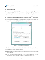
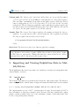
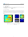
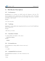
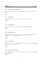
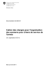
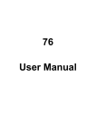
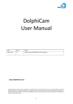
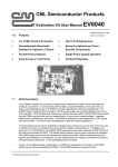
DolphiCamTM Research 1.3 User Manual
Fredrik Lingvall
February 5, 2015
1
February 5, 2015
Revision 3851
Contents
1 Introduction
4
2 New GUI Elements for the DolphiCamTM Research
4
3 Importing and Viewing DolphiCam Data in Matlab/Octave
5
3.1
load dc data . . . . . . . . . . . . . . . . . . . . . . . . . . . . . . . . . .
5
3.2
dc data viewer . . . . . . . . . . . . . . . . . . . . . . . . . . . . . . . . .
6
A File Header Description
7
A.1 DataDimension . . . . . . . . . . . . . . . . . . . . . . . . . . . . . . . . .
7
A.2 TimeStamp . . . . . . . . . . . . . . . . . . . . . . . . . . . . . . . . . . . .
7
A.3 CameraSerialNumber . . . . . . . . . . . . . . . . . . . . . . . . . . . . . .
7
A.4 SoftwareVersion . . . . . . . . . . . . . . . . . . . . . . . . . . . . . . . .
7
A.5 IsAssumedToBeInitialized . . . . . . . . . . . . . . . . . . . . . . . . . .
7
A.6 CurrentSettingsFileName . . . . . . . . . . . . . . . . . . . . . . . . . .
8
A.7 FpgaVersion . . . . . . . . . . . . . . . . . . . . . . . . . . . . . . . . . .
8
A.8 FpgaSubVersion . . . . . . . . . . . . . . . . . . . . . . . . . . . . . . . .
8
A.9 HardwareVersion . . . . . . . . . . . . . . . . . . . . . . . . . . . . . . . .
8
A.10 HoldOffTime . . . . . . . . . . . . . . . . . . . . . . . . . . . . . . . . . .
8
A.11 AmplitudeGatingStart . . . . . . . . . . . . . . . . . . . . . . . . . . . .
8
A.12 AmplitudeGatingEnd . . . . . . . . . . . . . . . . . . . . . . . . . . . . . .
9
A.13 TimeOfFlightGatingStart . . . . . . . . . . . . . . . . . . . . . . . . . .
9
A.14 TimeOfFlightGatingEnd . . . . . . . . . . . . . . . . . . . . . . . . . . . .
9
A.15 AmplitudeGatingStart2 . . . . . . . . . . . . . . . . . . . . . . . . . . . .
9
A.16 AmplitudeGatingEnd2 . . . . . . . . . . . . . . . . . . . . . . . . . . . . .
9
A.17 TimeOfFlightGatingStart2 . . . . . . . . . . . . . . . . . . . . . . . . . . 10
A.18 TimeOfFlightGatingEnd2 . . . . . . . . . . . . . . . . . . . . . . . . . . . 10
A.19 AmplitudeGatingStart3 . . . . . . . . . . . . . . . . . . . . . . . . . . . . 10
A.20 AmplitudeGatingEnd3 . . . . . . . . . . . . . . . . . . . . . . . . . . . . . 10
A.21 TimeOfFlightGatingStart3 . . . . . . . . . . . . . . . . . . . . . . . . . . 10
A.22 TimeOfFlightGatingEnd3 . . . . . . . . . . . . . . . . . . . . . . . . . . . 11
A.23 TxLine . . . . . . . . . . . . . . . . . . . . . . . . . . . . . . . . . . . . . . 11
A.24 RxLine . . . . . . . . . . . . . . . . . . . . . . . . . . . . . . . . . . . . . . 11
A.25 CameraModeSwitch . . . . . . . . . . . . . . . . . . . . . . . . . . . . . . . 11
2
February 5, 2015
Revision 3851
A.26 CameraType . . . . . . . . . . . . . . . . . . . . . . . . . . . . . . . . . . . 11
A.27 IsTimeCalibrationActive . . . . . . . . . . . . . . . . . . . . . . . . . . 11
A.28 IsScanButtonRegisterSet . . . . . . . . . . . . . . . . . . . . . . . . . . 12
A.29 IsScanButtonPushed . . . . . . . . . . . . . . . . . . . . . . . . . . . . . . 12
A.30 IsLowBattery . . . . . . . . . . . . . . . . . . . . . . . . . . . . . . . . . . 12
A.31 NumberOfTransmittingElements . . . . . . . . . . . . . . . . . . . . . . . 12
A.32 AveragesPerTransducerElement . . . . . . . . . . . . . . . . . . . . . . . 12
A.33 CaptureMethod . . . . . . . . . . . . . . . . . . . . . . . . . . . . . . . . . 13
A.34 IsEnteringSleepMode . . . . . . . . . . . . . . . . . . . . . . . . . . . . . 13
A.35 MatchFilterDivideFactor . . . . . . . . . . . . . . . . . . . . . . . . . . 13
A.36 TxPulseShapeAndMatchFilter . . . . . . . . . . . . . . . . . . . . . . . . 13
A.37 BScanXCoord . . . . . . . . . . . . . . . . . . . . . . . . . . . . . . . . . . 13
A.38 BScanYCoord . . . . . . . . . . . . . . . . . . . . . . . . . . . . . . . . . . 14
A.39 IsTimeCorrectedGainActive . . . . . . . . . . . . . . . . . . . . . . . . . 14
A.40 IsTimeCorrectedGainSubpointsActive . . . . . . . . . . . . . . . . . . . 14
A.41 TimeCorrectedGainValues . . . . . . . . . . . . . . . . . . . . . . . . . . 14
A.42 TimeCorrectedGainValuesSubPoints . . . . . . . . . . . . . . . . . . . . 14
A.43 DacValue . . . . . . . . . . . . . . . . . . . . . . . . . . . . . . . . . . . . 15
A.44 DacOffsetValue . . . . . . . . . . . . . . . . . . . . . . . . . . . . . . . . 15
A.45 RecordingWindowSamples . . . . . . . . . . . . . . . . . . . . . . . . . . . 15
A.46 IsRawDataRecording . . . . . . . . . . . . . . . . . . . . . . . . . . . . . . 15
A.47 FilterEnable . . . . . . . . . . . . . . . . . . . . . . . . . . . . . . . . . . 15
A.48 EnablePulseSequence . . . . . . . . . . . . . . . . . . . . . . . . . . . . . 16
A.49 TxPulseSeqA . . . . . . . . . . . . . . . . . . . . . . . . . . . . . . . . . . 16
A.50 TxPulseSeqB . . . . . . . . . . . . . . . . . . . . . . . . . . . . . . . . . . 16
A.51 EnableSleepMode . . . . . . . . . . . . . . . . . . . . . . . . . . . . . . . . 16
A.52 SleepModeWarningTime . . . . . . . . . . . . . . . . . . . . . . . . . . . . 17
A.53 CameraScanTime . . . . . . . . . . . . . . . . . . . . . . . . . . . . . . . . 17
A.54 DcCorrection . . . . . . . . . . . . . . . . . . . . . . . . . . . . . . . . . . 17
3
February 5, 2015
1
Revision 3851
Introduction
This document describes DolphiCamTM Research version 1.3 of the DolphiCamTM acoustic
camera. DolphiCamTM Research is a variant of the normal DolphiCamTM with additional
support for saving ultrasound sensor data and use user defined transmit pulses.
2
New GUI Elements for the DolphiCamTM Research
The DolphiCamTM Research Windows application has a new window for acquiring data
in its graphical user interface (GUI) which is shown in Figure 1.
Figure 1: DolphiCamTM Research GUI.
The Research window is activated from the Tools menu by selecting the Research
features item and it has the following elements:
Envelope The Envelope check box switches the envelop on/and off in the A-scan and
the two B-scans.
Filter The Filter check box switches filtering on and off when acquiring data. Note that
the filters can only be one of the 8 (CF08) or 4 (CF16) pre-defined ones.
4
February 5, 2015
Revision 3851
Custom pulse The Custom pulse editor has 8 fields where one can specify the number
of clock cycles a 15.625 ns (1/64 MHz) for each high and low of the pulse sequence.
One can define a maximum of four pulses in the pulse sequence where the allowed
range for high parts are 4–15 clock cycles and 6–15 clock cycles for the low parts,
respectively. The Set button programs the camera with the new pulse sequence and
the Clear button clears all the fields in the pulse editor (NB. Only the editor fields
are cleared, not the pulse sequence loaded in the camera).
Acquire Data The Acquire Data button switches off scanning and starts the data acquisition. A pop-up window will be shown during the data acquisition and when
the data is acquired the new file is stored in the
C:\Programdata\DolphiTech\DolphiCam\RawData
folder.
Start Scan The Start Scan/Stop Scan button toggles live scanning.
Note: It takes ≈ 12 seconds to acquire a CF08 data set and ≈ 24 seconds to acquire
a CF16 data set, respectively. During this time the camera should not be moved
otherwise there will be distortions in the acquired data.
3
Importing and Viewing DolphiCam Data in Matlab/Octave
The DolphiCamTM Research comes with a set of m-files for reading and viewing ultrasound
data in Matlab or Octave.
3.1
load dc data
The load dc data function reads ultrasound data in the .rdf (text) format. The function
takes a string with the .rdf file name as input and returns the ultrasound data in a matrix
>> Y = load_dc_data(’DolphiCam 13430025 2015-01-27 13-04-45.rdf’);
The output matrix as an L × 1242 + 1 matrix where L is the A-scan length and 1242 is
the total number of transducer elements on the 2D array. The first column in the output
matrix contains a sample index vector and remaining columns contain ultrasound data
for the corresponding array elements.
5
February 5, 2015
3.2
Revision 3851
dc data viewer
The dc data viewer function can be used for quick viewing of the data. It takes a matrix
in the format returned by the load dc data function,
>> dc_data_viewer(Y);
and presents two windows of the data. In Window 1 one first selects the position in a Cscan with the mouse (clicks) and then Window 2 shows a vertical and a horizontal B-scan
as well as an A-scan according to the position that was selected in Window 1. Figure 2
shows an example (an impact damage in a 6mm CFRP plate) of using the dc data viewer
function.
Y−Axis B−Scan
C−scan
Element #
1800
20
1600
1000
800
80
80
120
200
Sample Index
300
200
80
100
40
60
80
Element #
100
120
100
120
X−Axis B−Scan
50
1000
0
−1000
(a) Window 1.
150
200
250
350
0
120
100
300
−2000
60
Element #
20
A−Scan
400
40
80
2000
100
20
60
100
100
600
120
40
60
Sample Index
60
20
40
120
Amplitude [ADC Value]
1200
20
100
1400
Amplitude [ADC Value]
Element #
40
C−scan
Element #
2000
100
200
Sample Index
300
(b) Window 2.
Figure 2: Illustration of the dc data viewer function.
6
20
40
60
80
Element #
February 5, 2015
A
Revision 3851
File Header Description
A.1
DataDimension
DataDimension is a 6 element vector which describes the dimension of the data. The
first four numbers describe element layout of the 2D array the (it’s a 124 × 124 element
sensor) and the last two numbers describe the A-scan length of the data (i.e., start and
stop indexes of the A-scan).
Example:
0 0 123 123 0 359
A.2
TimeStamp
TimeStamp is a string with the time stamp when the file was created by the DolphiCamTM
Windows application.
Example:
2015-01-21_15-12-09
A.3
CameraSerialNumber
is a string with the serial number of the camera.
CameraSerialNumber
Example:
13060013
A.4
SoftwareVersion
SoftwareVersion is a string with the software version used.
Example:
1.3.3450
A.5
IsAssumedToBeInitialized
IsAssumedToBeInitialized is a Boolean for internal use only.
Example:
False
7
February 5, 2015
A.6
Revision 3851
CurrentSettingsFileName
CurrentSettingsFileName is a string with the name of the current settings file if any.
Example:
Default
A.7
FpgaVersion
FpgaVersion is an integer with the major version of the FPGA firmware.
Example:
135
A.8
FpgaSubVersion
FpgaSubVersion is an integer with the minor version of the FPGA firmware.
Example:
13
A.9
HardwareVersion
HardwareVersion is an integer with model type of the camera. A HardwareVersion < 10
is a CF08 camera and a HardwareVersion >= 10 is a CF16 camera.
Example:
10
A.10
HoldOffTime
HoldOffTime is an integer with the number of samples from the start of the transmit
pulse to the start of the data acquisition.
Example:
360
A.11
AmplitudeGatingStart
AmplitudeGatingStart is an integer with the start sample index of the 1st amplitude
gate (for future use).
Example:
8
February 5, 2015
Revision 3851
50
A.12
AmplitudeGatingEnd
is an integer with the end sample index of the 1st amplitude gate (for future use).
AmplitudeGatingEnd
Example:
350
A.13
TimeOfFlightGatingStart
TimeOfFlightGatingStart is an integer with the start sample index of the 1st time-offlight gate (for future use).
Example:
50
A.14
TimeOfFlightGatingEnd
is an integer with the end sample index of the 1st time-of-flight gate (for future use).
TimeOfFlightGatingEnd
Example:
350
A.15
AmplitudeGatingStart2
AmplitudeGatingStart2 is an integer with the start sample index of the 2nd amplitude
gate (for future use).
Example:
0
A.16
AmplitudeGatingEnd2
AmplitudeGatingEnd2 is an integer with the end sample index of the 2nd amplitude gate
(for future use).
Example:
0
9
February 5, 2015
A.17
Revision 3851
TimeOfFlightGatingStart2
TimeOfFlightGatingStart2 is an integer with the start sample index of the 2nd timeof-flight gate (for future use).
Example:
0
A.18
TimeOfFlightGatingEnd2
TimeOfFlightGatingEnd2 is an integer with the end sample index of the 2nd time-offlight gate (for future use).
Example:
0
A.19
AmplitudeGatingStart3
AmplitudeGatingStart3 is an integer with the start sample index of the 3rd amplitude
gate (for future use).
Example:
0
A.20
AmplitudeGatingEnd3
AmplitudeGatingEnd3 is an integer with the end sample index of the 3rd amplitude gate
(for future use).
Example:
0
A.21
TimeOfFlightGatingStart3
TimeOfFlightGatingStart3 is an integer with the start sample index of the 3rd time-offlight gate (for future use).
Example:
0
10
February 5, 2015
A.22
Revision 3851
TimeOfFlightGatingEnd3
TimeOfFlightGatingEnd3 is an integer with the end sample index of the 3rd time-of-flight
gate (for future use).
Example:
0
A.23
TxLine
TxLine is an integer describing the current horizontal cross hair position (for future use).
Example:
31
A.24
RxLine
RxLine is an integer describing the current vertical cross hair position (for future use).
Example:
31
A.25
CameraModeSwitch
CameraModeSwitch is a string with the position of the of the mode switch on the camera.
Example:
Normal
A.26
CameraType
CameraType a string with the type of the DolphiCamTM .
Example:
Expert
A.27
IsTimeCalibrationActive
IsTimeCalibrationActive is a Boolean indicating whether time calibration is used or
not (for internal use only).
Example:
11
February 5, 2015
Revision 3851
True
A.28
IsScanButtonRegisterSet
IsScanButtonRegisterSet is a Boolean indicating the status of an internal register (for
internal use only).
Example:
False
A.29
IsScanButtonPushed
IsScanButtonPushed is a Boolean indicating if the scan button has been pressed on the
camera (for internal use only).
Example:
False
A.30
IsLowBattery
IsLowBattery is a Boolean which indicates if the battery was low when the data was
acquired.
Example:
False
A.31
NumberOfTransmittingElements
NumberOfTransmittingElements is an integer with the number of transmit elements used
when acquiring the data.
Example:
4
A.32
AveragesPerTransducerElement
AveragesPerTransducerElement is an integer with the number of averages used when
acquiring the data.
Example:
2
12
February 5, 2015
A.33
Revision 3851
CaptureMethod
CaptureMethod is one of the following strings
CaptureGreatestAbsoluteValue
CaptureHighestValue
CaptureLowestValue
which indicates the method used to create the C-scan.
A.34
IsEnteringSleepMode
IsEnteringSleepMode is a Boolean which indicates that the camera will sleep in the
number seconds defined by SleepModeWarningTime which normally is 15 seconds (see
also Section A.52).
Example:
False
A.35
MatchFilterDivideFactor
MatchFilterDivideFactor is an integer used internally when filtering the data.
Example:
512
A.36
TxPulseShapeAndMatchFilter
TxPulseShapeAndMatchFilter is an integer defining the pulse (and the corresponding
filter) used when acquiring the data (1–8 for a CF08 camera and 1–4 for a CF16 camera).
Example:
1
A.37
BScanXCoord
BScanXCoord is an integer describing the current horizontal cross hair position (for future
use).
Example:
62
13
February 5, 2015
A.38
Revision 3851
BScanYCoord
BScanYCoord is an integer describing the current horizontal cross hair position (for future
use).
Example:
61
A.39
IsTimeCorrectedGainActive
IsTimeCorrectedGainActive is a Boolean which indicates if time-corrected gain is active.
Example:
False
A.40
IsTimeCorrectedGainSubpointsActive
IsTimeCorrectedGainSubpointsActive is a Boolean which indicates if sub points of
time-corrected gain is active.
Example:
False
A.41
TimeCorrectedGainValues
TimeCorrectedGainValues is an integer vector with the values of the internal digital-toanalog converter (DAC) used for time-corrected gain.
Example:
30 31 32 33 34 35 36 37 38 39 40 41 42 43
A.42
TimeCorrectedGainValuesSubPoints
TimeCorrectedGainValuesSubPoints is an integer vector with the values of the DAC
used for time-corrected gain sub-points.
Example:
30 31 32 33 34 35 36 37 38 39 40 41 42
14
February 5, 2015
A.43
Revision 3851
DacValue
DacValue is an integer used when setting the internal DAC for adjusting the sensor gain.
The gain is set using two integers DacValue and DacOffsetValue (see Section A.44). The
DAC value = DacValue + DacOffsetValue.
Example:
30
A.44
DacOffsetValue
DacOffsetValue is an integer used when setting the internal DAC for adjusting the sensor
gain (see also Section A.43).
Example:
6
A.45
RecordingWindowSamples
RecordingWindowSamples is an integer describing the A-scan length in samples.
Example:
360
A.46
IsRawDataRecording
IsRawDataRecording a Boolean that indicates whether we record data or not (it should
always be true).
Example:
True
A.47
FilterEnable
FilterEnable a Boolean that indicates whether the data is filtered or not.
Example:
True
15
February 5, 2015
A.48
Revision 3851
EnablePulseSequence
EnablePulseSequence a Boolean that indicates whether a custom pulse is enabled or
not.
Example:
False
A.49
TxPulseSeqA
TxPulseSeqA is the 2 byte integer which defines the first two pulses in of the pulse sequence
definition.
Example:
17990
which is
0x4646
in hexadecimal form. The first nibble (from left) is the number of clock cycles the pulse
is high and the second nibble is the number of cycles the pulse is low. The format of the
nibbles are (H - high, L - low):
0xHLHL
The valid range of H is 0x00,0x04–0x0F (0,4–15) and the valid range of a range of L is
0x00,0x06–0x0F (0,6–15). If all H are > 0, also in TxPulseSeqB (see Section A.50), then
four pulses are used.
A.50
TxPulseSeqB
TxPulseSeqB is the 2 byte integer which defines the last two pulses in of the pulse sequence
definition. (see Section A.49 for a description of the format).
A.51
EnableSleepMode
EnableSleepMode a Boolean that shows if the sleep mode feature is enabled.
Example:
True
16
February 5, 2015
A.52
Revision 3851
SleepModeWarningTime
SleepModeWarningTime is the number of seconds that the sleep mode warning is shown
before the camera enters sleep mode.
Example:
15
A.53
CameraScanTime
CameraScanTime is the number of minutes before the camera enters sleep mode.
Example:
15
A.54
DcCorrection
DcCorrection is a Boolean that indicates whether DC correction (bias correction) is on
or not. It should always be enabled.
Example:
True
17