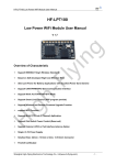
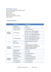
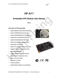
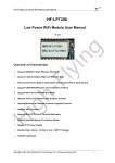
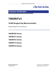
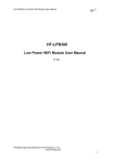
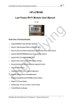
1
Low power wifi module UART TTL rs232 to 802.11 b/g/n converter
www.tcp232.net
Low Power WiFi Module User Manual
V 1.0
Overview of Characteristic
Support IEEE802.11b/g/n Wireless Standards
Fully Self-Contained Serial-to-Wireless Functionality
Ultra-Low-Power for Battery Applications with Excellent Power Save Scheme
Support UART/SPI/GPIO Data Communication Interface
Support Work As STA/Ad-Hoc Mode
Support SoftAP Mode with One STA Connected
Support Internal/External Antenna Option
Support AT+ Instruction Set for Configuration
Support UART Free/Auto Frame
Single +3.3V Power Supply
Smallest Size: 20 x 25mm
FCC/CE Certificate
-1-
Jinan USR Technology Co., Ltd.
Page 1 of 40
[email protected]
Low power wifi module UART TTL rs232 to 802.11 b/g/n converter
www.tcp232.net
TABLE OF CONTENTS
LIST OF FIGURES...................................................................................................................................4
LIST OF TABLES ....................................................................................................................................4
HISTORY..................................................................................................................................................5
1.
PRODUCT OVERVIEW ................................................................................................................6
1.1. General Description.................................................................................................................6
1.1.1
Device Features..................................................................................................................6
1.1.2
Device Paremeters .............................................................................................................7
1.1.3
Key Application ...................................................................................................................7
1.2.
Hardware Introduction ............................................................................................................8
1.2.1.
Pins Definition .....................................................................................................................8
1.2.2.
Electrical Characteristics ....................................................................................................9
1.2.3.
Mechanical Size................................................................................................................10
1.2.4.
External Antenna ..............................................................................................................10
1.2.5.
Evaluation Kit ....................................................................................................................10
1.3.
Typical Application ................................................................................................................12
1.3.1.
2.
3.
Hardware Typical Application ...........................................................................................12
FUNCTIONAL DESCRIPTION ..................................................................................................14
2.1. Wireless Networking .............................................................................................................14
2.1.1.
Basic Wireless Network Based On AP (Infrastructure) ....................................................14
2.1.2.
Wireless Network Based On Adhoc Network (Adhoc) .....................................................14
2.2.
Work Mode : Transparent Transmission Mode ..................................................................14
2.3.
UART Frame Scheme ............................................................................................................15
2.3.1.
UART Free-Frame ............................................................................................................15
2.3.2.
UART Auto-Frame ............................................................................................................15
2.4.
Encryption ..............................................................................................................................15
2.5.
Advanced WiFi Features .......................................................................................................16
2.6.
Soft AP Function Features....................................................................................................16
2.7.
Network Protocal ...................................................................................................................16
2.8.
Wireless Throughput Performance......................................................................................17
2.9.
Power Save Scheme ..............................................................................................................18
2.10.
Parameters Configuration .................................................................................................19
2.11.
Firmware Update ................................................................................................................19
2.12.
GPIO Function ....................................................................................................................20
OPERATION GUIDELINE ..........................................................................................................21
3.1. Low Power WiFi Module Usage Introduction......................................................................21
3.1.1.
Software Debug Tools ......................................................................................................21
3.1.2.
Network Connection .........................................................................................................21
3.1.3.
Module Debug ..................................................................................................................21
3.2.
Typical Application Examples ..............................................................................................23
3.2.1.
Wireless Control Application.............................................................................................23
3.2.2.
Remote Management Application ....................................................................................23
-2
Jinan USR Technology Co., Ltd.
Page 2 of 40
[email protected]
Low power wifi module UART TTL rs232 to 802.11 b/g/n converter
3.2.3.
4.
Transparent Serial Port Application..................................................................................24
AT+INSTRUCTION INTRODUCTION ......................................................................................25
4.1. Configuration Mode ...............................................................................................................25
4.1.1.
4.2.
5.
www.tcp232.net
Switch to Configuration Mode...........................................................................................25
AT+ Instruction Set Overview...............................................................................................26
4.2.1.
Instruction Syntax Format.................................................................................................26
4.2.2.
AT+ Instruction Set ...........................................................................................................27
4.2.2.1.
AT+E .............................................................................................................................28
4.2.2.2.
AT+WMODE .................................................................................................................28
4.2.2.3.
AT+ENTM .....................................................................................................................28
4.2.2.4.
AT+MID .........................................................................................................................29
4.2.2.5.
AT+VER ........................................................................................................................29
4.2.2.6.
AT+RELD ......................................................................................................................29
4.2.2.7.
AT+Z .............................................................................................................................29
4.2.2.8.
AT+H .............................................................................................................................29
4.2.2.9.
AT+UART......................................................................................................................30
4.2.2.10.
AT+ UARTF ...............................................................................................................30
4.2.2.11.
AT+ UARTFT.............................................................................................................30
4.2.2.12.
AT+ UARTFL .............................................................................................................31
4.2.2.13.
AT+ UARTTE.............................................................................................................31
4.2.2.14.
AT+NETP ..................................................................................................................31
4.2.2.15.
AT+ TCPLK ...............................................................................................................32
4.2.2.16.
AT+ TCPTO...............................................................................................................32
4.2.2.17.
AT+WSSSID..............................................................................................................32
4.2.2.18.
AT+WSKEY ...............................................................................................................33
4.2.2.19.
AT+ WANN ................................................................................................................33
4.2.2.20.
AT+ LANN .................................................................................................................33
4.2.2.21.
AT+ WSLK.................................................................................................................34
4.2.2.22.
AT+ WSLQ ................................................................................................................34
4.2.2.23.
AT+WSCAN...............................................................................................................34
4.2.2.24.
AT+PSPAR................................................................................................................34
4.2.2.25.
AT+MSLP ..................................................................................................................35
4.2.2.26.
AT+MSOPT ...............................................................................................................35
4.2.2.27.
AT+TSPAR ................................................................................................................36
4.2.2.28.
AT+WMAC.................................................................................................................36
4.2.2.29.
AT+WRMID ...............................................................................................................36
4.2.2.30.
AT+ASWD .................................................................................................................36
PACKAGE INFORMATION ........................................................................................................37
5.1. Recommended Reflow Profile ..............................................................................................37
5.2.
Device Handling Instruction (Module IC SMT Preparation)...............................................37
5.3.
Shipping Information.............................................................................................................38
APPENDIX A: HW REFERENCE DESIGN ......................................................................................3
-3-
Jinan USR Technology Co., Ltd.
Page 3 of 40
[email protected]
Low power wifi module UART TTL rs232 to 802.11 b/g/n converter
www.tcp232.net
LIST OF FIGURES
Figure 1.
Figure 2.
Low Power WiFi Module Demo..............................................................................................8
Low Power WiFi Module Pins Map ........................................................................................8
Figure 3.
Low Power WiFi Module Mechanical Dimension .................................................................10
Figure 4.
Low Power WiFi Module Evaluation Kit ...............................................................................11
Figure 5.
Low Power WiFi Module Hardware Typical Application.......................................................12
Figure 6.
Low Power WiFi Module Basic Wireless Network Structure................................................14
Figure 7.
Low Power WiFi Module Adhoc Network Structure .............................................................14
Figure 8.
STA Interface Debug Connection ........................................................................................21
Figure 9.
“CommTools” Serial Debug Tools........................................................................................21
Figure 10.
“TCPUDPDbg” Tools Create Connection.........................................................................22
Figure 11.
“TCPUDPDbg” Tools Setting............................................................................................22
Figure 12.
“TCPUDPDbg” Tools Connection.....................................................................................23
Figure 13.
Wireless Control Application.............................................................................................23
Figure 14.
Remote Management Application ....................................................................................24
Figure 15.
Transparent Serial Port Application..................................................................................24
Figure 16.
Low Power WiFi Module Default UART Port Parameters ................................................25
Figure 17.
Switch to Configuration Mode...........................................................................................25
Figure 18.
”AT+H” Instruction for Help...............................................................................................26
Figure 19.
Reflow Soldering Profile ...................................................................................................37
Figure 20.
Shipping Information.........................................................................................................38
LIST OF TABLES
Table 1
Table 2
Low Power WiFi Module Technical Specifications..................................................................7
Low Power WiFi Module Pins Definition .................................................................................8
Table 3
Low Power WiFi Module External Antenna Parameters .......................................................10
Table 4
Low Power WiFi Module Evaluation Kit Interface Description ..............................................11
Table 5
Low Power WiFi Module IP Stack Features..........................................................................17
Table 6
Low Power WiFi Module IPv4 Throughput............................................................................17
Table 7
Low Power WiFi Module IPv6 Throughput............................................................................17
Table 8
Power Consumption with Different Power Save Mode .........................................................18
Table 9
Usage Activity Wake up Time ................................................................................................19
Table 10
Low Power WiFi Module GPIO Pin Mapping Table ............................................................20
Table 11
Error Code Describtion........................................................................................................27
Table 12
AT+ Instruction Set List .......................................................................................................27
-4-
Jinan USR Technology Co., Ltd.
Page 4 of 40
[email protected]
Low power wifi module UART TTL rs232 to 802.11 b/g/n converter
www.tcp232.net
HISTORY
Ed. V0.1 Created on 7-26-2012.
Ed. V0.3 Add AT+ instruction set introduction.
Ed. V1.0 Released 9-17-2012.
-5-
Jinan USR Technology Co., Ltd.
Page 5 of 40
[email protected]
Low power wifi module UART TTL rs232 to 802.11 b/g/n converter
www.tcp232.net
1. PRODUCT OVERVIEW
1.1. General Description
The Low Power WiFi Module is a fully self-contained small form-factor, single stream, 802.11b/g/n WiFi module, which provide a wireless interface to any equipment with a serial or SPI interface for data
transfer.Low Power WiFi Module integrate MAC, baseband processor, RF transceiver with power
amplifier in hardware and all Wi-Fi protocol and configuration functionality and networking stack, in
embedded firmware to make a fully self-contained 802.11b/g/n Wi-Fi solution for a variety of
applications.
The Low Power WiFi Module is targeted at applications that send infrequent data packets over the
network. Typically, these 802.11 applications will place a higher priority on system cost, power
consumption, ease of use, and fast wake-up times as compared to high throughput.
The Low Power WiFi Module employs the world's lowest power consumption embedded architecture.
It has been optimized for all kinds of client applications in the home automation, smart grid, handheld
device, personal medical application and industrial control that have lower data rates, and transmit or
receive data on an infrequent basis. The module features standby current consumption of less than
1uA while still monitoring peripherals.
The Low Power WiFi Module integrates all Wi-Fi functionality into a low-profile, 20 mm x 25 mm SMT
module package that can be easily mounted on main PCB with application specific circuits. Also,
module provides built-in antenna, external antenna connector and an interface port to the carrier
board.
1.1.1 Device Features
Single stream Wi-Fi @ 2.4 GHz with support for WEP security mode as well as WPA/WPA2
Fully self-contained serial-to-wireless functionality.
Ultra-low-power operation with all kinds of power-save modes.
Includes all the protocol and configuration functions for Wi-Fi connectivity.
WPS support
SoftAP mode support
Host interface through Serial Interface and SPI.
Wide range of connector ports including SPI, UART ports and ADC/DAC, PWM, GPIO ports.
Integrated chip antenna, antenna connector, and RF line output options.
Optional support for built-in web server.
Compact surface mount module 20x25mm.
Full IPv4 and IPv6 stack.
Low power RTOS and drivers.
FCC Certified.
RoHS and CE compliant.
Single supply – 3.3V operation.
-6
Low Power WiFi Module User Manual V1.0
Jinan USR Technology Co., Ltd.
Page 6 of 40
[email protected]
Low power wifi module UART TTL rs232 to 802.11 b/g/n converter
www.tcp232.net
1.1.2 Device Paremeters
Table 1
Class
Wireless
Low Power WiFi Module Technical Specifications
Item
Parameters
Certification
FCC/CE
Wireless standard
Frequency range
802.11 b/g/n
2.412GHz-2.484GHz
802.11b: +18.5 dBm (@1Mbps)
802.11g: +16.5 dBm (@54Mbps)
802.11n: +10.5 dBm (@HT20, MCS7)
802.11b: -87 dBm (@11Mbps ,CCK)
802.11g: -74dBm (@54Mbps, OFDM)
802.11n: -71dBm (@HT20, MCS7)
External:I-PEX Connector
Internal:On-board chip antenna
RF Line: link to main board through pad
UART
GPIOs
Others: SPI, ADC/DAC, PWM…
3.1~3.6V
Peak [Continuous TX]: 200mA
Normal [WiFi ON/OFF, DTIM=100ms]:
Average. 5mA, Peak: 200mA
Deep Sleep: [WiFi OFF]: <~2uA
Standby [WiFi Shutdown]: <1uA
Refer “Power Save Scheme” Chapter
Transmit Power
Parameters
Receiver Sensitivity
Antenna Option
Data Interface
Operating Voltage
Hardware
Operating Current
Parameters
Operating
Temperature
Storage Temperature
Dimensions and Size
Network Type
Security Mechanisms
Encryption
Software
Parameters
Transition Time
Serial command
Network Protocol
User Configuration
-30℃- 85℃
-40℃- 125℃
20×25×2mm
STA /Ad-Hoc/SoftAP mode
WEP/WPA-PSK/WPA2-PSK/WPS
WEP64/WEP128/TKIP/AES
Deep Sleep to Normal: ~115ms
Standby to Normal: 195ms (Same AP)
Standby to Normal: 500ms (rescan)
AT+instruction set
IPv4, IPv6,TCP/UDP/FTP/HTTP
AT+instruction set. Android/ iOS
1.1.3 Key Application
Remote equipment monitoring
Asset tracking and telemetry
Security
Industrial sensors and controls
Home automation
Medical devices
-7-
Jinan USR Technology Co., Ltd.
Page 7 of 40
[email protected]
Low power wifi module UART TTL rs232 to 802.11 b/g/n converter
www.tcp232.net
1.2. Hardware Introduction
Figure 1.
Low Power WiFi Module Demo
1.2.1 Pins Definition
Figure 2.
Low Power WiFi Module Pins Map
Table2
Low Power WiFi Module Pins Definition
Pin
Description
Name
Note
GND
Directio
n
Power
1,17,22,2
4
2
3
4
Ground
No Connect
WPS Input (GPIO3)
UART1 Data Receive
NC
WPS
UART1_RX
O
I, IPU
I
UART1 Data Transmit
Module Reset signal
Module Ready Indicator
(GPIO7)
UART1_TX
nReset
nReady
O
I, IPU
O, IPU
Reserved for RF testing.
WiFi Protected Setup input.
Low Energy UART (Optional)
Default as GPIO functional pin
5
6
7
“Low” effective reset input.
“0” - Finish boot up process;
“1” - Module boot up not finish.
-8Jinan USR Technology Co., Ltd.
Page 8 of 40
[email protected]
Low power wifi module UART TTL rs232 to 802.11 b/g/n converter
www.tcp232.net
8
Pin Sleep Indicator
(GPIO8)
Sleep_ON
O, IPD
9
I2C Serial Data
(GPIO9)
I2C Serial Clock
(GPIO10)
WiFi Status Indication
(GPIO11)
Restore Configuration
(GPIO12)
I2C_SDA
I/O, IPU
“0”- Module in sleep status;
“1”- Module in awake status;
No connect if sleep not used.
I2C Serial Data input/output.
I2C_SCL
O, IPU
I2C Serial Clock Line output.
nLINK
O, IPU
nReload
I, IPU
13
Firmware Update Enable
UD
I, IPD
14,15
16
18
No Connect
VCC
UART0 Data Transmit
NC
VCC3V3
UART0_TX
I/O
Power
O
19
20
UART0 Data Receive
Pin Sleep Control
(GPIO20)
UART0_RX
Sleep_RQ
I
I, IPD
“0”- WIFI connected
“1”- No WIFI connection
Module will restore factory
default configuration after set
this pin “0” more than 3s, then
set “1”. No connect if not used.
“0”- Module normal operation.
“1”- Module ready for firmware
update through UART0 after
reset operation.
Reserved for MFG testing.
3.3V@ 250mA
General Data Communication
Interface
21
23
GPIO functional pin
2.4GHz Antenna line out
GPIO21
Ant_2.4G
I/O
O
10
11
12
1.2.2.
“0”- Drive module to sleep;
“1”- Wake up the module;
No connect if sleep not used.
GPIO, PWM functional pin
Must 50ohm line
Electrical Characteristics
Absolute Maximum Ratings:
Power Supply & Power Consumption:
-9-
Jinan USR Technology Co., Ltd.
Page 9 of 40
[email protected]
Low power wifi module UART TTL rs232 to 802.11 b/g/n converter
Input leakage current
I/O pull up resistor
www.tcp232.net
+/-25
nA
Kohm
40
I/O pull down resistor
Analog input range
40
0
3
Kohm
V
Analog output range
0
3
V
1.2.3. Mechanical Size
Low Power WiFi Modules physical size (Unit: mm) as follows:
Figure 3.
1.2.4.
Low Power WiFi Module Mechanical Dimension
External Antenna
Low Power WiFi Module supports internal antenna and external antenna option for user dedicated
application.
If user select external antenna, Low Power WiFi Modules must be connected to the 2.4G antenna
according to IEEE 802.11b/g/n standards.
The antenna parameters required as follows:
Table 3
1.2.5.
Low Power WiFi Module External Antenna Parameters
Item
Frequency range
Parameters
2.4~2.5GHz
Impedance
VSWR
Return Loss
Connector Type
50 Ohm
2 (Max)
-10dB (Max)
I-PEX or populate directly
Evaluation Kit
Manufacturer provides the evaluation kit to promote user to familiar the product and develop the
detailed application. The evaluation kit shown as below, user can connect to Low Power WiFi Module
- 10
Jinan USR Technology Co., Ltd.
Page 10 of 40
[email protected]
Low power wifi module UART TTL rs232 to 802.11 b/g/n converter
www.tcp232.net
with the RS-232 UART port or Wireless port to configure the parameters, manage the module or do
the some functional tests.
Figure 4.
Low Power WiFi Module Evaluation Kit
The external interface description for evaluation kit as follows:
Table 4
Function
External
Interface
Name
COM1
Description
Main data/command RS-232 interface
P1
3-Pin UART0 RS-232 interface.
COM2
Low Power data RS-232 interface (Optional)
P2
3-Pin UART1 RS-232 interface.
DC5-18V
DC jack for power in, 5~15V input
ATT
2.4GHz SMA connector for external antenna.
JP2
GPIO
Debug
JP1
LED
Button
Low Power WiFi Module Evaluation Kit Interface Description
Power
nLink
nReady
Sleep_ON
I/O21
nReset
nReload
WPS
Sleep_RQ
Low Power WiFi Module power current test interface
connector
Low Power WiFi Module GPIO function extend
interface connector
Reserved, leave open
Firmware Update Jumper.
Leave open for normal operation. Add Jumper for
updated Low Power WiFi Module firmware
download from COM1.
3.3V Power Indicator
nLink -WiFi LINK Indicator
nReady – Module Bootup Ready Indicator
Sleep_ON-Module asleep or awake Indicator
GPIO21 functional Indicator, PWM
Used to reset the module.
Restore factory default configuration after push this
pin more than 3s.
WPS Button
Pin Sleep Control button, more than 1s to put
module in standby mode.
- 11 -
Jinan USR Technology Co., Ltd.
Page 11 of 40
[email protected]
Low power wifi module UART TTL rs232 to 802.11 b/g/n converter
www.tcp232.net
1.3. Typical Application
1.3.1.
Hardware Typical Application
Figure 5.
Low Power WiFi Module Hardware Typical Application
Notes
Notes:
nReset- Module hardware reset signal. Input. Logics “0” effective.
There is pull-up resister internal and no external pull-up required. When module power up or some
issue happened, MCU need assert nRST signal “0” at least 10ms, then set” 1” to keep module fully
reset.
nLink- Module WIFI connection status indication. Output.
When module connects to AP (AP associated), this pin will output “0”. This signal used to judge if
module already at WiFi connection status. Thers is pull-up resister internal and no external pull-up
required. If n Link function not required, can leave this pin open.
nReady- Module boot up ready signal. Output. Logics “0” effective.
The module will output “0” after normal boot up. This signal used to judge if module finish boot up and
ready for application or working at normal mode. If nReady function not required, can leave this pin
open.
WPS – module auto-negotiation with AP and acquire password and build link
User can de-asser this pin low ”0”, after 500ms, then asser this pin high “1” to enable the auto
negotiation.if AP also push its WPS button, then Module and AP will start auto-negotiation and
module acquire password and build link. Next time, module will link with same AP without autonegotiation required. User can use “AT+WSSSID” and “AT+WSKEY” command to query SSID and
password.
- 12 -
Jinan USR Technology Co., Ltd.
Page 12 of 40
[email protected]
Low power wifi module UART TTL rs232 to 802.11 b/g/n converter
www.tcp232.net
nReload
nReload- Module restore to factory default configuration.Input. Logics “0” effective.
User can de-assert nReload signal “0” more than 3s through button or MCU pin, then release, module
will restore to factory default configuration and re-start boot up process. Thers is pull-up resister
internal and no external pull-up required. If nReload function not required, can leave this pin open.
Sleep-RQ- Module Pin Sleep Control. Input.
The user should de-assert this pin low “0”, after 1’s assert to high ”1” to put the module to sleep status.
Also at the deep sleep/standby mode, user can de-assert this pin low “0”, after 1’s assert to high ”1”
to put the module to wake up the module. If user doesn't use pin sleep function, can leave this pin
open.
Sleep-ON- Module Pin Sleep Indicator. Output.
This pin is used to indicate that the module is asleep (Module output “0”) or awake (Module output “1”)
status. If user doesn't use pin sleep function, can leave this pin open.
Detailed Sleep function describtion, pls refer to 2.9.
UART0_TXD/RXD
UART0_TXD/RXD- UART port data transmit and receive signal.
- 13 -
Jinan USR Technology Co., Ltd.
Page 13 of 40
[email protected]
Low power wifi module UART TTL rs232 to 802.11 b/g/n converter
www.tcp232.net
2. FUNCTIONAL DESCRIPTION
2.1. Wireless Networking
2.1.1.
Basic Wireless Network Based On AP (Infrastructure)
Infrastructure: it’s also called basic network. It built by AP and many STAs which join in.
The characters of network of this type are that AP is the centre, and all communication between STAs
is transmitted through the AP. The figure following shows such type of networking.
Figure 6.
2.1.2.
Low Power WiFi Module Basic Wireless Network Structure
Wireless Network Based On Adhoc Network (Adhoc)
Adhoc: It’s also called independent basic service set, and it’s built by two STAs without AP, this type
of network is a loose structure, all the STAs in the network can communicate directly. Note that ad hoc
networks are point to point and that there can only be two nodes in the network, a creator and a joiner.
Set up the creator first, and then the joiner.
Figure 7.
Low Power WiFi Module Adhoc Network Structure
2.2. Work Mode : Transparent Transmission Mode
Low Power WiFi Module support serial interface transparent transmission mode. The benefit of this
mode is achieves a plug and play serial data port, and reduces user complexity furthest. In this mode,
user should only configure the necessary parameters. After power on, module can automatically
connect to the default wireless network and server.
As in this mode, the module's serial port always work in the transparent transmission mode, so users
- 14 -
Jinan USR Technology Co., Ltd.
Page 14 of 40
[email protected]
Low power wifi module UART TTL rs232 to 802.11 b/g/n converter
www.tcp232.net
only need to think of it as a virtual serial cable, and send and receive data as using a simple serial. In
other words, the serial cable of users’ original serial devices is directly replaced with the module; user
devices can be easy for wireless data transmission without any changes.
The transparent transmission mode can fully compatible with user’s original software platform and
reduce the software development effort for integrate wireless data transmission.
2.3. UART Frame Scheme
2.3.1.
UART Free-Frame
Low Power WiFi Module support UART free-frame function. If user select open this function, module
will check the intervals between any two bytes when reciving UART data. If this interval time exceeds
defined value (50ms default), Low Power WiFi Module will think it as the end of one frame and transfer
this free-frame to WiFi port, or Low Power WiFi Module will receive UART data untill 1400 bytes, then
transfer 1400 bytes frame to WiFi port.
Low Power WiFi Module’s default interval time is 50ms. User can also set this interval to fast (10ms)
through AT command. But user have to consider if user MCU can send UART data with 10ms
interval ,or the UART data may be divide as fragment.
Through AT command: AT+UARTTE=fash/normal, user can set the interval time: fast (10ms) and
normal (50ms).
2.3.2.
UART Auto-Frame
Low Power WiFi Module support UART auto-frame function. If user select open this function and
setting auto-frame trigger length and auto-frame trigger time parameters, then module will auto
framing the data which received from UART port and transmitting to the network as pre-defined data
structure.
Auto-frame trigger length
length: The fixed data length that module used to transmitting to the
network.
Auto-frame trigger time: After the trigger time, if UART port received data can’t reach autoframe trigger length, then module will transmitting available data to the network and bypass
the auto-frame trigger length condition.
Detailed UART auto-frame function can refer to AT+ instruction set “UARTF/UARTFT/UARTFL”
introduction.
2.4. Encryption
Encryption is a method of scrambling a message that makes it unreadable to unwanted parties,
adding a degree of secure communications. There are different protocols for providing encryption, and
the Low Power WiFi Module supports following:
WEP
- 15
Jinan USR Technology Co., Ltd.
Page 15 of 40
[email protected]
Low power wifi module UART TTL rs232 to 802.11 b/g/n converter
www.tcp232.net
WPA-PSK/TKIP
WPA-PSK/AES
WPA2-PSK/TKIP
WPA2-PSK/AES
2.5. Advanced WiFi Features
Low Power WiFi Module automatically implements a variety of advanced WiFi features, these WiFi
features includes:
WWR, 802.11d
WiFi Protected Setup (WPS) 2.0
Self-managed power state handling
Self-contained beacon processing
Shared authentication
2.6. Soft AP Function Features
Low Power WiFi Module supports Soft AP mode for user application development and testing of their
product. The AP features includes:
802.11 b/g/n AP mode
Customized SoftAP setting, include
Channel
Beacon interval
Regulatory
Country code setting
Inactivity time
Security settings
IP settings
But, HP-LPA’s Soft AP feature also has following constraints:
The number of STAs that can connect is limited to 1
DTIM Value limit id fixed to 1
No support for 802.11n aggregation
No DHCP server support
Security is limited to WPA2-PSK/AES and open only
2.7. Network Protocal
Low Power WiFi Module includes a fully IPv4 and IPv6 capable stack supporting TCP and UDP
connection.Following table shows the key features of the Low Power WiFi Module IP stack, which
including support for DHCP, multicast, and ARP.
The Frame size limits are (including IP headers):
Tranmit
TCP/UDP/ICMP (v4): 1576
ICMP (v6): 1576
- 16 -
Jinan USR Technology Co., Ltd.
Page 16 of 40
[email protected]
Low power wifi module UART TTL rs232 to 802.11 b/g/n converter
www.tcp232.net
UCP/UDP (v6): 1220
Receive
TCP/UDP (v4): 1516
TCP/UDP (v6): 1496
ICMPv4 and ICMPv6: 5000
Table 5
Low Power WiFi Module IP Stack Features
Feature
Support
ARP
Supported
Forwarding
Supported
Fragmentation/Reassembly
Planned
IPv4/v6 Header Processing
Supported
UDP/TCP Socket Support
Supported
DHCP v4
Neighbor Discovery
Client Support
Supported
Broadcast/Multicast
Path MTU Discovery
Address Auto-Configuration
Multicast
TCP Zero Copy Feature
Supported
Supported
Supported
Planned
Supported
2.8. Wireless Throughput Performance
Performance is affected by many factors. The Low Power WiFi Module itself can deliver throughputs
at experted 11n rates. However, systerm constraints due to cost and other reasons may affect the net
end to end throughput. The perforamce measured for IPv4 is doing using 1400 byte packets.
Performance measured for IPv6 is doning using 1400 byte packets. The result as following tables:
Table 6
Low Power WiFi Module IPv4 Throughput
IPv4
Offload
UDP
Uplink (Low Power WiFi Module
AP)
5.51 Mbps
Downlink (AP Low Power WiFi
Module)
6.01 Mbps
TCP
5.14 Mbps
5.96 Mbps
Table 7
Low Power WiFi Module IPv6 Throughput
IPv6
Offload
UDP
Uplink (Low Power WiFi Module
AP)
5.10 Mbps
Downlink (AP Low Power WiFi
Module)
5.63 Mbps
TCP
5.00 Mbps
5.62 Mbps
- 17 -
Jinan USR Technology Co., Ltd.
Page 17 of 40
[email protected]
Low power wifi module UART TTL rs232 to 802.11 b/g/n converter
www.tcp232.net
2.9. Power Save Scheme
Low Power WiFi Module can work at three modes based on different power save scheme:
Normal (Active/Sleep) Mode - AP Associated, WiFi ON/OFF based on internal control
Deep Sleep Mode - Non AP Associated, WiFi OFF
Standby Mode - Non AP Associated, WiFi Shut dwon
Normal (Active/Sleep) Mode Normal mode support two work option: One is no DTIM related (Default
mode), module will monitor the interval to Active/Sleep. The other is DTIM related mode, whcih allows
the module to sync up with beacons sent from the AP which contains the DTIM (Delivery Traffic
Indication Message). The DTIM indicates when broadcast and multicast data will be sent on the
network. This property is configured on the AP (Default value is 1, which means DTIM= 100ms) and is
typically configured as the number of beacons between each beacon with DTIM.
Deep Sleep/Standby Mode allows the WiFi circuitry to be “OFF” status or powered down, which
results in the lower/lowest sleep current, but at the expense of longer wake up times. This is due to
the module associating with the access point every time when it wakes up. The intent of this option is
to allow for longer sleep times.
Following typical measurement parameters can be used for select suitable power save scheme based
on the real application case:
Table 8
Power Consumption with Different Power Save Mode
WiFi Mode
Condition
Average Current
Peak Current
Standby
WiFi Shutdown
20nA ~0.9uA
< 1uA
Deep Sleep
WiFi OFF
~2uA
< 10uA
Normal
(Active/Sleep)
Normal
(Active/Sleep)
Normal
(Active/Sleep)
WiFi ON - AP Connected
DTIM = 100ms
WiFi ON – AP Connected
DTIM = 500ms
WiFi ON – AP Connected
DTIM = 1000ms
~ 5mA
< 220mA
~ 1mA
< 220mA
~ 0.5mA
< 220mA
In addition, for deep sleep/standby mode, module provides three wakes up options, user can select
one or whole as the module wake up option. Refer to AT Instruction (Power Management Instruction
Set) for more detailed setting.
Pin Wake Up
UART Wake Up
Timeout Wake Up
Pin Wake Up Option allows an external microcontroller to determine when Low Power WiFi Module
should sleep and when it should wake by controlling the “Sleep_RQ” and “Sleep_ON” pin. at the deep
sleep/standby mode, user can de-assert this pin low “0”, after 1’s assert to high ”1” to put the module
to wake up the module. If user doesn't use pin sleep function, can leave this pin open.
- 18 -
Jinan USR Technology Co., Ltd.
Page 18 of 40
[email protected]
Low power wifi module UART TTL rs232 to 802.11 b/g/n converter
www.tcp232.net
UART Wake Up Option. Low Power WiFi Module can use AT command to put module into
normal/sleep mode. When module works at deep sleep or standby mode, user can use ”AT+MSLP
=normal” to wake up module. Refer to 4.2.2.23 for more detail.
Timeout Wake Up Option allows the sleep timeout period to be configured through the use of AT
Instruction.In this option, the module will exit sleep based on the <Timeout> AT Instruction parameters.
For control battery usage, user can increase <Timeout> period. It is user’s responsibility to configure <
Timeout > as needed every time. User can set <Timeout> parameter cyclic or every time for each
cycle, which provide much flexibility for control and synchronous in each side.
Following typical wake up parameters based on different conditions can be used for select suitable
sleep scheme based on the real application case.
Table 9
Usage Activity Wake up Time
Condition
Typical Wake up Time
From “OFF” until ready to transmit when STA loses connection on
wakeup
(And re-associating to the same AP on the same channel)
From “OFF” until ready to transmit when STA loses connection on
wakeup
(And a complete rescan is required)
190ms
500ms
2.10. Parameters Configuration
Low Power WiFi Module supports AT+instruction set configuration parameters:
AT+instruction set configuration means user configure parameters through serial interface command.
Refer to “AT+instruction set” chapter for more detail.
2.11. Firmware Update
Low Power WiFi Module supports firmware update though UART0 interface.
To enter the firmware update mode, Pin UD (pin 13) must be pulled high and then the module must be
reset. If Pin UD is low (Low Power WiFi Module has internal pull-down for this pin. Leaving this pin
unconnected is low), the module will check the firmware in the flash. If contains a valid firmware, the
module will continue to run the firmware. If there is not a valid firmware present, module will sleep to
conserve power, while periodically checking the pin UD.
The firmware update though UART0 interface now.The UART0 use 1 stop bit, no parity and 8 data
bits. To enable a wide variety of different terminals Low Power WiFi Module uses autobaud. The
autobaud functionality sense the baudrate used by the terminal program and adjusts accordingly.This
is done by sending one capital 'U' to the module. The module senses the timing between bits and
adjusts its own prescaler to match the sensed baudrate. The module works with baudrates in the
range from 57600 to 460800 for firmware update usage.
Note: Always confirm with Manufacturer technical support before any firmware update operation. Or it
may damage the module permanently.
- 19 -
Jinan USR Technology Co., Ltd.
Page 19 of 40
[email protected]
Low power wifi module UART TTL rs232 to 802.11 b/g/n converter
www.tcp232.net
2.12. GPIO Function
Low Power WiFi Module can provide maximum 11 GPIO pins, Refer to “1.2.1 Pin Definition” charter,
which include 2 Low Power UART pins, 2 I2C interface pins, 2 Pin sleep control pins, 2 Link status pin,
1 reloafd functional pin, 1 PWM control pin and 1 general GPIO pin. All these pins can be customized
as GPIO pins if these functions are not required. As GPIO functional pin, user devices can read/write
GPIO pins status through AT+instruction set.
Table 10
GPIO
Low Power WiFi Module GPIO Pin Mapping Table
GPIO3
Configured
Function
WPS
Describtion
GPIO4
UART1 Data Receive
GPIO5
GPIO20
UART1 Data
Transmit
Sleep_RQ
GPIO8
Sleep_ON
GPIO9
I2C_SDA
GPIO10
I2C_SCL
I2C EEPROM
interface
GPIO11
nLINK
WiFi Link status
“nLINK”
O,IPU
GPIO12
nReload
nReload function
“nReload”
I,IPU
GPIO7
nReady
nReady function
“nReady”
O,IPU
GPIO21
GPIO21
GPIO function
GPIO21
I/O
WiFi Protected
Setup
Low Energy UART
(Optional)
Pin Sleep Control
Default
Setting
Type
WPS
I,IPU
GPIO4
I/O
GPIO5
I/O
Sleep_RQ
I, IPD
Sleep_ON
O,OPD
I2C_SDA
I/O, IPU
I2C_SCL
O, IPU
- 20 -
Jinan USR Technology Co., Ltd.
Page 20 of 40
[email protected]
Low power wifi module UART TTL rs232 to 802.11 b/g/n converter
www.tcp232.net
3. OPERATION GUIDELINE
3.1. Low Power WiFi Module Usage Introduction
3.1.1.
Software Debug Tools
Manufacturer use two common software tools debugging and applying Low Power WiFi Module.
(User can also select other tools used to debug serial port).
Serial Debugging Software: ComTools
Ethernet Debugging Software: TCPUDPDbg
3.1.2.
Network Connection
User can use folloing method to connect Low Power WiFi Module base on dedicated application.
Low Power WiFi Module and debug PC2 connect to a wireless AP, another PC1 (or user device)
connect to Low Power WiFi Module with serial port:
Figure 8.
3.1.3.
STA Interface Debug Connection
Module Debug
PC1 open “CommTools” program, setting the same serial port parameters with Low Power WiFi
Module and open serial port connection.
Figure 9.
“CommTools” Serial Debug Tools
- 21 -
Jinan USR Technology Co., Ltd.
Page 21 of 40
[email protected]
Low power wifi module UART TTL rs232 to 802.11 b/g/n converter
www.tcp232.net
PC2 open “TCPUDPDbg” program, and create a new connection. If Low Power WiFi Module
configured as Server mode, “TCPUDPDbg” Tools shall create “Client “mode connection. Or otherwise,
create a “Server” mode connection.
Figure 10.
“TCPUDPDbg” Tools Create Connection
Then setting the TCP/UDP connection parameters. Default as following:
Figure 11.
“TCPUDPDbg” Tools Setting
Then, click “Create” button to create a connection.
- 22 -
Jinan USR Technology Co., Ltd.
Page 22 of 40
[email protected]
Low power wifi module UART TTL rs232 to 802.11 b/g/n converter
www.tcp232.net
Figure 12.
“TCPUDPDbg” Tools Connection
Now, in transparent transmission mode, data can be transferred from “CommTools” program to
“TCPUDPDbg” program, or in reverse. You can see data in receiver side will keep same as in sender
side.
3.2. Typical Application Examples
3.2.1.
Wireless Control Application
Figure 13. Wireless Control Application
For this wireless control application, Low Power WiFi Module works as Ad-Hoc mode. Module’s serial
port connects to user device. So, control agent (Smart phone for this example) can manage and
control the user device through the wireless connection with Low Power WiFi Module.
3.2.2.
Remote Management Application
- 23 -
Jinan USR Technology Co., Ltd.
Page 23 of 40
[email protected]
Low power wifi module UART TTL rs232 to 802.11 b/g/n converter
www.tcp232.net
Figure 14. Remote Management Application
For this remote management application, Low Power WiFi Module works as STA mode and connects
to Internet through wireless AP. Module configured as TCP Client and communicates with remote
TCP server at Internet. Module’s serial port connects to user device.
So, user device’s data or sampling information can send to remote TCP server for storage or
processing. Also remote TCP server can send command to control and manage the user device
through the wireless network.
3.2.3.
Transparent Serial Port Application
For this transparent serial port application, two Low Power WiFi Modules connect as below figures to
build up a transparent serial port connection. Low Power WiFi Module works as Ad-Hoc mode to
connect each other.
Figure 15. Transparent Serial Port Application
- 24 -
Jinan USR Technology Co., Ltd.
Page 24 of 40
[email protected]
Low power wifi module UART TTL rs232 to 802.11 b/g/n converter
www.tcp232.net
4. AT+INSTRUCTION INTRODUCTION
4.1. Configuration Mode
When Low Power WiFi Module power up, it will default works as transparent transmission mode, then
user can switch to configuration mode by serial port command. Low Power WiFi Module UART default
parameters setting as below figure,
Figure 16. Low Power WiFi Module Default UART Port Parameters
In configuration mode, user can setting the module through AT+ instruction set, which cover all web
page setting function.
4.1.1.
Switch to Configuration Mode
Two steps to finish switching from transparent transmission mode to configuration mode.
”, and feedback “a” as confirmation.
UART input “+++
+++””, after module receive “+++
+++”
” to go into AT+
UART input “a”, after module receive “a” and feedback “+ok
+ok”
instruction set configuration mode.
Figure 17. Switch to Configuration Mode
Notes:
1. When user input “+++” (No “Enter” key required), the UART port will display feedback information
“a”, and not display input information”+++” as above UART display.
2. Any other input or wrong step to UART port will cause the module still works as original
mode (transparent transmission).
- 25 -
Jinan USR Technology Co., Ltd.
Page 25 of 40
[email protected]
Low power wifi module UART TTL rs232 to 802.11 b/g/n converter
www.tcp232.net
4.2. AT+ Instruction Set Overview
User can input AT+ Instruction through hyper terminal or other serial debug terminal, also can
program the AT+ Instruction to script. User can also input “AT+H” to list all AT+ Instruction and
description to start.
Figure 18. ”AT+H” Instruction for Help
4.2.1.
Instruction Syntax Format
AT+Instruction protocol is based on the instruction of ASCII command style, the description of syntax
format as follow.
Format Description
< >: Means the parts must be included
[ ]:
Means the optional part
Command Message
…]<CR>
AT+<CMD>[op][para-1,para-2,para-3,para-4
AT+<CMD>[op][para-1,para-2,para-3,para-4…
AT+: Prefix of command message;
CMD: Command string;
[op]:
Symbol of command operator,
“=” : The command requires parameters input;
“NULL”: Query the current command parameters setting;
[para-n]: Parameters input for setting if required;
<CR>:”Enter” Key, it’s 0x0a or 0x0d in ASCII;
Notes: When input AT+Instruction, “AT+<CMD>” character will display capital letter automatic and
other parts will not change as you input.
- 26 -
Jinan USR Technology Co., Ltd.
Page 26 of 40
[email protected]
Low power wifi module UART TTL rs232 to 802.11 b/g/n converter
www.tcp232.net
Response Message
…]<CR><LF><CR><LF>
+<RSP>[op] [para-1,para-2,para-3,para-4
[para-1,para-2,para-3,para-4…
+: Prefix of response message;
RSP: Response string;
“ok” : Success
“ERR”: Failure
[op] : =
[para-n]: Parameters if query command or Error code when error happened;
<CR>: ASCII 0x0d;
<LF>: ASCIII 0x0a;
Error Code
Table 11
Error Code
-1
-2
-3
-4
-5
4.2.2.
Error Code Describtion
Description
Invalid Command Format
Invalid Command
Invalid Operation Symbol
Invalid Parameter
Operation Not Permitted
AT+ Instruction Set
Table 12
AT+ Instruction Set List
Instruction
Description
<null>
NULL
Managment Instruction Set
E
Open/Close show back function
WMODE
Set/Query WIFI work mode (ADHOC or STA)
ENTM
Set module into transparent transmition mode
MID
Query module ID information
VER
Query module software version information
RELD
Restore to factory default setting
Z
Re-start module
H
Help
UART Instruction Set
UART
Set/Query serial port parameters
UARTF
Open/Close UART auto-frame function
UARTFT
Set/Query UART auto-frame trigger time
UARTFL
Set/Query UART auto-frame trigger length
UARTTE
Set/Query UART free-frame triggerf time between two
bytes
Network Instruction Set
NETP
Set/Query network protocol parameters
TCPLK
Query if TCP link already build-up
- 27 -
Jinan USR Technology Co., Ltd.
Page 27 of 40
[email protected]
Low power wifi module UART TTL rs232 to 802.11 b/g/n converter
www.tcp232.net
TCPTO
Set/Query TCP timeout
WiFi STA Instruction Set
WSKEY
Set/Query WIFI security parameters as STA
WSSSID
Set/Query WIFI target AP SSID parameters as STA
WANN
Set/Query WAN setting, only effective as STA mode
WSLK
Query WiFi link status as STA
WSLQ
Query WiFi signal strength as STA
WSCAN
Seek AP when module works as STA mode
LANN
Set/Query LAN setting,only effective as ADHOC mode
Power Management Instruction Set
PSPAR
Set/Query power save parameters at NORMAL mode
MSOPT
Set/Query wake up option parameters
MSLP
Set/Query deep sleep/standby mode parameters
TSPAR
Set/Query timeout wake up parameters
Others Instruction Set
WMAC
Query WiFi interface MAC address
WRMID
Set module ID
ASWD
Set/Query WiFi configuration code
4.2.2.1. AT+E
Function: Open/Close show back function;
Format:
AT+E<CR>
+ok<CR>< LF ><CR>< LF >
When Low Power WiFi Module firstly switch from transparent transmission to configuration mode,
show back status is open, input “AT+E” to close show back function, input“AT+E” again to open show
back function.
4.2.2.2. AT+WMODE
Function: Set/Query WIFI work mode;
Format:
Query Operation
AT+WMODE<CR>
+ok=<mode><CR>< LF ><CR>< LF >
Set Operation
AT+ WMODE=<mode><CR>
+ok<CR>< LF ><CR>< LF >
Parameters:
mode:WIFI work mode
ADHOC
STA
4.2.2.3. AT+ENTM
Function: Set module into transparent transmition mode;
Format:
- 28 -
Jinan USR Technology Co., Ltd.
Page 28 of 40
[email protected]
Low power wifi module UART TTL rs232 to 802.11 b/g/n converter
www.tcp232.net
AT+ENTM<CR>
+ok<CR>< LF ><CR>< LF >
When operate this command, module switch from configuration mode to transparent transmission
mode.
4.2.2.4. AT+MID
Function: Query module ID information;
Format:
Query Operation
AT+MID<CR>
+ok=<module_id><CR>< LF ><CR>< LF >
Parameters:
module_id: Module ID information;
Low Power WiFi Module;
Notes: User can set this parameter through AT+WRMID.
4.2.2.5. AT+VER
Function: Query module software version information;
Format:
Query Operation
AT+VER<CR>
+ok=<ver><CR>< LF ><CR>< LF >
Parameters:
ver: Module software version information;
4.2.2.6. AT+RELD
Function: module restore to factory default setting;
Format:
Set Operation
AT+ RELD<CR>
…<CR>< LF ><CR>< LF >
+ok=rebooting
+ok=rebooting…
When operate this command, module will restore to factory default setting and reboot.
4.2.2.7. AT+Z
Function: Re-start module;
Format:
AT+ Z<CR>
4.2.2.8. AT+H
Function: Help;
Format:
Query Operation
AT+H<CR>
+ok=<commod help><CR>< LF ><CR>< LF >
- 29 -
Jinan USR Technology Co., Ltd.
Page 29 of 40
[email protected]
Low power wifi module UART TTL rs232 to 802.11 b/g/n converter
www.tcp232.net
Parameters:
commod help: command introduction;
4.2.2.9. AT+UART
Function: Set/Query serial port parameters;
Format:
Query Operation
AT+UART<CR>
+ok=<baudrate,data_bits,stop_bit,parity><CR>< LF ><CR>< LF >
Set Operation
AT+UART=<baudrate,data_bits,stop_bit,parity><CR>
+ok<CR>< LF ><CR>< LF >
Parameters:
baudrate:
300,600,1200,1800,2400,4800,9600,19200,38400,57600,115200,230400,380
400
data_bits:
8
stop_bits:
1,2
parity:
NONE,EVEN,ODD
4.2.2.10. AT+ UARTF
Function: Open/Close UART auto-frame function;
Format:
Query Operation
AT+ UARTF<CR>
+ok=<para><CR>< LF ><CR>< LF >
Set Operation
AT+ UARTF=<para ><CR>
+ok<CR>< LF ><CR>< LF >
Parameters:
para:
disable
- Close auto-frame function;
enable
- Open auto-frame function;
4.2.2.11. AT+ UARTFT
Function: Set/Query UART auto-frame trigger time;
Format:
Query Operation
AT+ UARTFT<CR>
+ok=<time><CR>< LF ><CR>< LF >
- 30 -
Jinan USR Technology Co., Ltd.
Page 30 of 40
[email protected]
Low power wifi module UART TTL rs232 to 802.11 b/g/n converter
www.tcp232.net
Set Operation
AT+ UARTFT=<time ><CR>
+ok<CR>< LF ><CR>< LF >
Parameters:
time: Range 100 ~10000; Unit: ms. Auto-frame trigger time
4.2.2.12. AT+ UARTFL
Function: Set/Query UART auto-frame trigger length;
Format:
Query Operation
AT+ UARTFL<CR>
+ok=<len><CR>< LF ><CR>< LF >
Set Operation
AT+ UARTFL=<len ><CR>
+ok<CR>< LF ><CR>< LF >
Parameters:
len: Range 16 ~1400; Unit: Byte. Auto-frame trigger length;
4.2.2.13. AT+ UARTTE
Function: Set/Query UART free-frame trigger time between two bytes;
Format:
Query Operation
AT+ UARTTE<CR>
+ok=<mode><CR>< LF ><CR>< LF >
Set Operation
AT+ UARTTE=<mode><CR>
+ok<CR>< LF ><CR>< LF >
Parameters:
mode:
fast: free-frame trigger time between two bytes is 10ms;
normal: free-frame trigger time between two bytes is 50ms;
4.2.2.14. AT+NETP
Function: Set/Query network protocol parameters;
Format:
Query Operation
AT+NETP<CR>
+ok=<protocol,CS,port,IP><CR>< LF ><CR>< LF >
Set Operation
AT+NETP=<protocol,CS,port,IP><CR>
+ok<CR>< LF ><CR>< LF >
Parameters:
protocol:
TCP
- 31 -
Jinan USR Technology Co., Ltd.
Page 31 of 40
[email protected]
Low power wifi module UART TTL rs232 to 802.11 b/g/n converter
www.tcp232.net
UDP
CS: Network mode:
SERVER
CLIENT
Port: protocol port ID: Decimal digit and less than 65535
IP: Server’s IP address when module set as client
4.2.2.15. AT+ TCPLK
Function: Query if TCP link already build-up;
Format:
AT+ TCPLK<CR>
+ok=<sta><CR>< LF ><CR>< LF >
Parameters:
sta.: if module already setup TCP link;
on: TCP link setup;
off: TCP link not setup;
4.2.2.16. AT+ TCPTO
Function: Set/Query TCP timeout;
Format:
Query Operation
AT+ TCPTO<CR>
+ok=<time><CR>< LF ><CR>< LF >
Set Operation
AT+ TCPTO=<time ><CR>
+ok<CR>< LF ><CR>< LF >
Parameters:
time: TCP timeout time.
<= 600, (600s);
>=0, (0 means no timeout);
Default, 300s;
4.2.2.17. AT+WSSSID
Function: Set/Query WIFI target AP SSID parameters as STA.
Format:
Query Operation
AT+WSSSID<CR>
+ok=<ap
+ok=<ap’’s ssid><CR>< LF ><CR>< LF >
Set Operation
AT+ WSSSID=<ap
WSSSID=<ap’’s ssid ><CR>
+ok<CR>< LF ><CR>< LF >
Parameters:
ap’s ssid: AP’s SSID (Within 20 character);
- 32 -
Jinan USR Technology Co., Ltd.
Page 32 of 40
[email protected]
Low power wifi module UART TTL rs232 to 802.11 b/g/n converter
www.tcp232.net
4.2.2.18. AT+WSKEY
Function: Set/Query WIFI security parameters as STA;
Format:
Query Operation
AT+WSKEY<CR>
+ok=<auth,encry,key><CR>< LF ><CR>< LF >
Set Operation
AT+ WSKEY=< auth,encry,key><CR>
+ok<CR>< LF ><CR>< LF >
Parameters:
auth: Authentication mode
OPEN
SHARED
WPAPSK
WPA2PSK
encry:Encryption algorithm
NONE: When “auth=OPEN”, effective
WEP: When “auth=OPEN” or “SHARED”, effective
TKIP: When ”auth= WPAPSK” or “WPA2PSK”, effective
AES:
When “auth= WPAPSK” “WPA2PSK”, effective
key: password, ASCII code, shall less than 64 bit and greater than 8bit
4.2.2.19. AT+ WANN
Function: Set/Query WAN setting, only effective as STA mode;
Format:
Query Operation
AT+WANN<CR>
+ok=<mode,address,mask,gateway><CR>< LF ><CR>< LF >
Set Operation
AT+ WANN=< mode,address,mask,gateway ><CR>
+ok<CR>< LF ><CR>< LF >
Parameters:
mode: IP setting for WAN port
static: Static IP
DHCP: Dynamic IP
address: WAN port IP address;
mask: WAN port subnet mask;
gateway: WAN port gateway address;
4.2.2.20. AT+ LANN
Function: Set/Query the IP address under ADHOC mode;
Format:
Query Operation
- 33 -
Jinan USR Technology Co., Ltd.
Page 33 of 40
[email protected]
Low power wifi module UART TTL rs232 to 802.11 b/g/n converter
www.tcp232.net
AT+LANN<CR>
+ok=<ipaddress,mask><CR>< LF ><CR>< LF >
Set Operation
AT+ LANN=< ipaddress,mask><CR>
+ok<CR>< LF ><CR>< LF >
Parameters:
ipaddress: IP address under ADHOC mode;
mask: Net mask under ADHOC mode;
4.2.2.21. AT+ WSLK
Function: Query WiFi link status as STA
Format:
Query Operation
AT+ WSLK<CR>
+ok=<ret><CR>< LF ><CR>< LF >
Parameters:
ret
”Disconnected”, if no WiFi connection;
”AP’ SSID(AP’s MAC” ), if WiFi connection available;
”RF Off”, if WiFi OFF;
4.2.2.22. AT+ WSLQ
Function: Query WiFi signal strength as STA
Format:
Query Operation
AT+ WSLQ<CR>
+ok=<ret><CR>< LF ><CR>< LF >
Parameters:
ret
”Disconnected”, if no WiFi connection;
”AP’s WiFi signal strength” , if WiFi connection available;
4.2.2.23. AT+WSCAN
Function: Seek AP when module works as STA mode;
Format:
AT+ WSCAN<CR>
+ok=<ap_site><CR>< LF ><CR>< LF >
Parameters:
ap_site: AP searched;
4.2.2.24. AT+PSPAR
Function: Set/ Query power save parameters at Normal mode;
Format:
- 34 -
Jinan USR Technology Co., Ltd.
Page 34 of 40
[email protected]
Low power wifi module UART TTL rs232 to 802.11 b/g/n converter
www.tcp232.net
Query Operation
AT+ PSPAR<CR>
+ok=<mode> <CR>< LF ><CR>< LF >
Set Operation
AT+ PSPAR=<mode> <CR>< LF ><CR>< LF >
Parameters:
mode:
pf:Continuous TX Mode (NO WiFi OFF)
Default, 100ms interval
ps1:Normal Mode, Disable DTIM (Default,
interval)
ps2:Normal Mode, Enable DTIM
4.2.2.25. AT+MSLP
Function: Set/Query deep sleep/standby mode parameters;
Format:
Query Operation
AT+ MSLP<CR>
+ok=<ret><CR>< LF ><CR>< LF >
Set Operation
AT+ MSLP=<mode><CR>< LF ><CR>< LF >
Parameters:
ret:
normal: normal mode (ps1: 100ms interval)
deep sleep: deep sleep mode [WiFi OFF]
standby: WiFi shut down mode
mode:
normal: normal mode (ps1: 100ms interval)
dslp: deep sleep mode [WiFi OFF]
standby: WiFi shut down mode
4.2.2.26. AT+MSOPT
Function: Set/Query wake up option parameters;
Format:
Query Operation
AT+ MSOPT<CR>
+ok=<wakeup_mode> <CR>< LF ><CR>< LF >
Set Operation
AT+ MSOPT=<wakeup_mode> <CR>< LF ><CR>< LF >
Parameters:
Wakeup_mode:
0b0001:UART Wake up
0b0010:Pin Wake up
0b0100:Timeout Wake up
Note: These 3 options can multi-selection, such as 0b0111 means all three wakes up option enabled.
- 35 -
Jinan USR Technology Co., Ltd.
Page 35 of 40
[email protected]
Low power wifi module UART TTL rs232 to 802.11 b/g/n converter
www.tcp232.net
4.2.2.27. AT+TSPAR
Function: Set/Query timeout wake up parameters;
Format:
Query Operation
AT+ TSPAR<CR>
+ok=<timeout> <CR>< LF ><CR>< LF >
Set Operation
AT+ TSPAR=<timeout> <CR>< LF ><CR>< LF >
Parameters:
timeout: set timeout time, unit: second.
4.2.2.28. AT+WMAC
Function: Query WiFi interface MAC address;
Format:
Query Operation
AT+ WMAC<CR>
+ok=<wmac> <CR>< LF ><CR>< LF >
Parameters:
wmac: query WiFi interface MAC address.
4.2.2.29. AT+WRMID
Function: Set module ID;
Format:
Set Operation
AT+ WRMID=<wrmid> <CR>< LF ><CR>< LF >
Parameters:
wrmid: set module’s ID (within 20 characters).
4.2.2.30. AT+ASWD
Function: Set/Query WiFi Configuration Password;
Format:
Query Operation
AT+ ASWD<CR>
+ok=<aswd> <CR>< LF ><CR>< LF >
Set Operation
AT+ ASWD=<aswd> <CR>< LF ><CR>< LF >
Parameters:
aswd: WiFi Configuration Password (within 20 characters).
- 36 -
Jinan USR Technology Co., Ltd.
Page 36 of 40
[email protected]
Low power wifi module UART TTL rs232 to 802.11 b/g/n converter
www.tcp232.net
5. PACKAGE INFORMATION
5.1. Recommended Reflow Profile
Figure 19. Reflow Soldering Profile
NO.
Item
1
Reflow
Time
Note: 1.
2
Peak-Temp
supply N2 for reflow oven.
Temperature
(Degree)
Time of above 220
Time(Sec
)
35~55 sec
260 max
Recommend to
2. N2 atmosphere during reflow (O2<300ppm)
5.2. Device Handling Instruction (Module IC SMT Preparation)
Shelf life in sealed bag: 12 months, at <30℃ and <60% relative humidity (RH)
1
.
After bag is opened, devices that will be re-baked required after last baked with window time
2
168 hours.
.
Recommend to oven bake with N2 supplied
Recommend end to reflow oven with N2 supplied
3
Baked required with 24 hours at 125+-5℃ before rework process for two modules, one is
.
new module and two is board with module
4
Recommend to store at ≦10% RH with vacuum packing
.
If SMT process needs twice reflow:
5
(1) Top side SMT and reflow
(2) Bottom side SMT and reflow
.
Case 1: Wifi module mounted on top side. Need to bake when bottom side process over 168
hours window time, no need to bake within 168 hours
6
Case 2: Wifi module mounted on bottom side, follow normal bake rule before process
.
Note: Window time means from last bake end to next reflow start that has 168 hours space.
7
.
- 37 -
Jinan USR Technology Co., Ltd.
Page 37 of 40
[email protected]
Low power wifi module UART TTL rs232 to 802.11 b/g/n converter
www.tcp232.net
5.3. Shipping Information
DRYPACK BAG
DRYPACK BAG HOLE DIRECTION
AFFIX PACKING LABEL
1 UNIT DESICCANT
AFFIX WARNING LABEL
PINK BUBBLE WRAP
HUMIDITY INDICATOR CARD
Figure 20. Shipping Information
Note: 1 tray = 168pcs
1 box = 10 trays = 10 * 168pcs=1,680pcs
- 38 -
Jinan USR Technology Co., Ltd.
Page 38 of 40
[email protected]
Low power wifi module UART TTL rs232 to 802.11 b/g/n converter
www.tcp232.net
APPENDIX A: HW REFERENCE DESIGN
-39-
Jinan USR Technology Co., Ltd.
Page 39 of 40
[email protected]
Low power wifi module UART TTL rs232 to 802.11 b/g/n converter
www.tcp232.net
6. Contact us
Contact us:
Name: Jinan USR Technology Co., Ltd.
Website: http://www.usr.cn http://www.tcp232.net
Address: Shengfu garden, D5-3-302, Jinan, Shandong, China
Email: [email protected]
MSN: [email protected]
Phone: 86-531-66592361
-40Jinan USR Technology Co., Ltd.
Page 40 of 40
[email protected]