1
PSZ 19:16(Pind.1/13)
UNIVERSITI TEKNOLOGI MALAYSIA
DECLARATION OF THESIS / UNDERGRADUATE PROJECT REPORT
Author’s full name : MUHAMMAD ASYRAF BIN BAHARUDDIN
Date of Birth
: 01.06.1992
Title
: AN UNDERWATER ULTRASONIC TRACKING DEVICE
Academic Session : 2014/2015
I declare that this thesisis classified as:
CONFIDENTIAL
(Contains confidential information under the Official Secret Act
1972)*
RESTRICTED
(Contains restricted information as
organization where research was done)*
OPEN ACCESS
I agree that my thesis to be published as online open access
(full text)
specified
by
the
I acknowledged that Universiti Teknologi Malaysia reserves the right as follows:
1. The thesis is the property of Universiti Teknologi Malaysia
2. The Library of Universiti Teknologi Malaysia has the right to make copies for the
purpose of research only.
Certified by:
NOTES:
SIGNATURE
SIGNATURE OF SUPERVISOR
920601-01-5913
Assoc. Prof. Dr.Sallehuddin bin
Ibrahim
(NEW IC NO/PASSPORT)
NAME OF SUPERVISOR
Date: 25st JUNE 2015
Date: 25st JUNE 2015
*
If the thesis is CONFIDENTAL or RESTRICTED, please attach with the letter from
the organization with period and reasons for confidentiality or restriction.
ii
“I hereby declare that I have read this final year project report and in my/our*opinion
this final year project report is sufficient in terms of scope and quality for theaward
of the degree of Bachelor of Electrical (Instrumentation and Control) Engineering”
Signature
: ………………………….........
Name of Supervisor
: Assoc. Prof. Dr. Sallehuddin bin
Ibrahim
Date
: 25th JUNE 2015
iii
AN UNDERWATER ULTRASONIC TRACKING DEVICE
MUHAMMAD ASYRAF BIN BAHARUDDIN
A final year project report submitted inpartialfulfilment of the
requirements for the award of the degree of
Bachelor of Engineering (Electrical – Instrumentation and Control)
Faculty of Electrical Engineering
Universiti Teknologi Malaysia
JUNE 2015
iv
I declare that this final year project report entitled “an underwater ultrasonic
tracking device” is the result of my own research except as cited in the references.
The final year project report has not been accepted for any degree and is not
concurrently submitted in candidature of any other degree.
Signature
:
....................................................
Name
:
MUHAMMAD ASYRAF BIN BAHARUDDIN
Date
:
25th JUNE 2015
v
Special dedicated for my parents, siblings and friends
Thanks for being supporting and encouragement
vi
ACKNOWLEDGEMENT
Praised be to Allah for His blessings. First and foremost, I would like to
thanks to Allah because He give me the strength to complete this undergraduate
project paper writing. The project is beginning from the Final Year Project 1 for the
semester 1 and Final Year Project 2 for semester 2.
Secondly, I would like to thanks and express my gratitude to my supervisor
which is Assosiate Professor Dr Sallehuddin Bin Ibrahim. He is the one who help
and guide me along this 2 semester. He is also gives me an inspiration while carrying
out the project. I will always remember because he always gives me a moral support.
Lastly, I would like to thanks to all my family members because of their
moral support. To all my friends, especially SKEI’s students who gives me a hand
while completing this project.
vii
ABSTRACT
Various industries require a precise, linear indication of the depth of water in
a specific part of the water. This demands a continuous level measurement.
Ultrasonic detectors can measures the distance between theseabed to the surface of
the water. To measure level and depth, with an ultrasonic range detector, the module
is mounted at the bottom of the sea in example, the seabed, looking up the surface.
We must measure the time between the transmit pulse and the echo received pulses.
Since the ultrasonic signal is travelling at the speed of sound, the time between
transmission and echo received is a measure of the distance to the surface, water
depth. The underwater ultrasonic tracking device here is focused on low cost
material. It is used to search an object under the water. The sensor only transmitted
to the large size of area. As a conclusion, it can detect within a range of 7cm.
viii
ABSTRAK
Pelbagai industry memerlukan, petunjuk linear tepat kedalam air di bahagian
tertentu dalam air. Ini memerlukan ukuran tahap yang berterusan. Pengesan
ultrasonic boleh mengukur antara permukaan dasar air ke permukaan air. Untuk
mengukur tahap dan kedalamannya, dengan pelbagai pengesan ultrasonic yang ada,
modul dipasang di bahagian bawah laut. Sebagai contoh, dasar laut, dilihat ke atas
permukaan air. Kita mesti mengukur masa antara denyutan penghantar dan gema
menerima denyutan. Selepas isyarat ultrasonic bergerak dengan kelajuan bunyi,
masa antara penghantaran dan echo diterima adalah ukuran jarak ke permukaan iaitu
kedalaman air. Peranti pengesan ultrasonic dalam air pada projek ini member
tumpuan kepada bahan kos rendah. Ia digunakan untuk mencari objek di bawah air.
Sensor hanya dihantar kepada saiz besar kawasan. Kesimpulannya, ia boleh
mengesan dalam pelbagai 7cm.
ix
TABLE OF CONTENTS
CHAPTER
TITLE
PAGE
ACKNOWLEDGEMENT
ABSTRACT
ABSTRAK
TABLE OF CONTENTS
LIST OF FIGURE
LIST OF TABLES
LIST OF ABBREVIATIONS
LIST OF APPENDICES
1
vi
vii
viii
ix
xi
xiii
xiv
xv
1.1
INTRODUCTION
Background
1
1
1.2
Problem Statement
2
1.3
Objectives
3
1.4
Scope Of Project
3
1.5
Organization Of Thesis
3
2.1
LITERATURE REVIEW
Introduction
4
4
2.2
Underwater Ultrasonic Tracking System
4
2.3
Ultrasonic Sensor
5
2.3.1Velocity Of Ultrasonic and Wavelength
7
2.3.2 Wave Propagation
8
2.3.3 Speed of Sound Waves in Air and Water
9
2
3
3.1
3.2
3.3
3.4
METHODOLOGY
10
Project Overview
11
Project Workflow
12
Underwater Ultrasonic Tracking Device
13
Hardware Development
13
3.4.1 Block Diagram and Flowchart of Underwater
Ultrasonic Tracking Device
13
x
3.5
3.6
4
3.4.2 Main Component in the Circuitry of Underwater
Ultrasonic Tracking Device
15
Hardware
15
3.5.1 Arduino UNO
15
3.5.2 Power
17
3.5.3 Memory Organization
18
3.5.4 HC-SR04
19
3.5.5 Basic Principle
21
3.5.6 Pin Configuration
22
3.5.7 Operation
23
3.5.8 Power HD 3001HB Servo Motor
24
3.5.9 The Dimension of the Power HD
3001HB Servo Motor
27
3.5.10 Power HD 3001 HB Working’s Principle 27
Software Implementation
28
3.6.1 Processing Software
28
3.6.2 Processing Development Environment
(PDE)
30
4.1
RESULT AND DISCUSSION
Introduction
31
31
4.2
Tracking System
31
4.3
4.2.1 Experimental In Air
4.2.2 Experimental In Water
4.2.3 Rotational System
Overall System Design
31
35
40
42
5.1
5.2
5.3
CONCLUSION
Introduction
Conclusion
Future Work
44
44
44
45
PROJECT MANAGEMENT
Introduction
6.1.1 Project Schedule
46
46
46
5
6
6.1
REFERENCES
APPENDICES A-B
48
50-52
xi
LIST OF FIGURES
FIGURE NO
TITLE
PAGE
2.1
The formula of wavelength
2.2
Illustration of the particle motion versus the direction of
wave
3.1
7
8
Overall design flow of underwater ultrasonic tracking
device
11
3.2
Flowchart of project flow
12
3.3
Block diagram of underwater ultrasonic tracking device
13
3.4
Flowchart of underwater ultrasonic tracking device
14
3.5
The Front Part ofArduino UNO R3
16
3.6
The Back Part of Arduino UNO R3
16
3.7
ATmega328 Pin out Diagram
18
3.8
ATmega328 Key Parameter
19
3.9
HC-SR04
20
3.10
The movement of sound wave after reach the object
22
3.11
HC-SR04 Pin Configuration
23
3.12
HC-SR04 Timing Diagram
24
3.13
The wire connection
25
3.14
Processing Display Window
29
3.15
Processing Development Environment Display Window
30
4.1
The data recorded based on the distance of object in the air 32
4.2
Graph of sensor detected distance vs distance measures
4.3
Hardware implementation (HC-SR04 sensor) for tracking
33
system
33
4.4
Hardware implementation for housing
35
4.5
Hardware implementation for first attempt
36
xii
4.6
The processing display window showing the detection
object
37
4.7
The distance value of ultrasonic sensor
37
4.8
The value of distance before calibrating the resolution
38
4.9
Graph of output value vs reference point
39
4.10
The rotation of ultrasonic sensor in the water
41
4.11
The limitation of servo motor
41
4.12
Schematic diagram of project
42
4.13
The overall hardware of circuit diagram
43
4.14
Overall hardware design
43
6.1
Gantt chart
47
xiii
LIST OF TABLES
TABLE NO
TITLE
PAGE
1
Power pins of Arduino board
17
2
The specification of servo motor
26
3
Result of sensor detected and measures distance
32
4
The result of reference point and output value
40
5
Project budget
47
xiv
LIST OF ABBREVIATIONS
AC
Alternating Current
AVR
Advanced Virtual RISC
DC
Direct Current
EEPROM
Electricity Erasable Programmable Read-Only Memory
I/O
Input / Output
IDE
Integrated Development Environment
LED
Light Emitting Diode
PDE
Processing Development Environment
PWM
Pulse Width Modulation
RC
Radio Control
SRAM
Static Random-Access Memory
USB
Universal Serial Bus
xv
LIST OF APPENDICES
APPENDIX
TITLE
PAGE
A
Tracking System Coding
50
B
Image Processing Coding
52
1
CHAPTER 1
INTRODUCTION
1.1
Background
Ultrasonic sensor has been applied since 1917 by Paul Langevin while he
was trying to emit sound waves in the sea water. He is also known as the father of
ultrasonic[1]. Nowadays, the developing of science for sound wave has been
implemented in various applications. The system can be applied for the sound
communication of submarines, measuring depth of sea, level of the tank or some
more. Ultrasound is also widely used in physical check up or investigations. In
industry, ultrasonic is used for cleaning, emulsifying or else. In biological, the
ultrasonic used for killing bacteria.
The term ultrasonic refers to the frequency of sound above 20 kHz. Basically,
the usage of ultrasonic in medical can be extended more than 10 MHz. For the
animals such as bat vision, dolphins or else commonly use a range of frequency
around 20 to 100 kHz. Commonly, the high frequency usage about 1 to 20 MHz used
in medical treatment. For any industries application, there are only use near to 20
kHz[2].
As stated above, the demanding of ultrasonic become increasing in many
type of industry. So the performance of ultrasonic can be different depends on the
characteristic, operating, specification and action taken by each industry. The
ultrasonic also had been increase their capability which is it is being use for
navigation or collision avoidance application[3]. For instrumentation application, it
2
is suitable to build up a measuring ultrasonic sensor such as finding or locating an
object. Nowadays, the underwater application also has been developed. The usage of
ultrasonic in the water can be seen through naval application such as communication
system, detecting object or else.
1.2
Problem Statement
In some cases, a suffocated person or object cannot be found because the
body object is carried away by the swift water or muddy water. For a few moments,
the dead bodies will start to sink to the bottom of a river or the sea. It will become
more difficult to search the dead body because there is no exactly coordination of the
dead body. It might take some times to search only one person in one time. To
remedy this condition, an underwater ultrasonic tracking device that uses an
ultrasonic has been developed.
Nowadays, there are a lot of ultrasonic sensor device invented but the usage
of ultrasonic depends on the characteristic or requirement of the application itself.
This is because not all the ultrasonic sensor has the same frequencies. For example,
the speed of sound in air is around 340 m/s while the speed in water is 1500 m/s. By
looking at the differences of medium, the ultrasonic sensor must be able to measure
the distance inside the water. From those characteristics, the ultrasound sensor can
be provided based on the desired specification of the transducer.
3
1.3
Objective
The main objective is to view the surface area underwater below 1m range.
The other objectives are as follows:
To assist the authority in searches an object inside the water.
To be used in a shallow water area.
To display the position of an object in the water by using a processing
software.
1.4
Scope of Project
There are several of project’s scope that can be implemented. The scope is
includes:
Using Arduino UNO and processing.
Using ultrasonic sensor (HC-SR04) to send and receive signal by
immersing underwater.
1.5
Using servo motor to keep rotating the sensor by 45° until 135°.
Organization of the Thesis
The thesis contains of an Introduction, Literature Review, Methodology,
Result and Discussion, Conclusion and lastly Project management.
Chapter 1 will be discussed about the problem statement, objectives and
scope of the project. Chapter 2 will be discussed the literature reviews. Chapter 3
will be discussed about the methodology. Chapter 4 will be discussed about the
results and discussion. Chapter 5 will be discussedabout the conclusion and
recommendation. Lastly, chapter 6 will be discussed about project management.
4
CHAPTER 2
LITERATURE REVIEW
2.1
Introduction
This chapter will review the relevant literature onunderwater ultrasonic
tracking.
2.2
Underwater Ultrasonic Tracking System
Underwater ultrasonic tracking device is one of the technologies used to
detect an object in the water. Nowadays, there are a lot of underwater tracking
device invented. Mostly, the price is very expensive. There are a few techniques of
underwater ultrasonic sensor application:
a) Underwater imaging system using acoustic holography
This type of system was developed to view some objects in muddy
water. The development is focus on to get the image by inventing remotecontrolled underwater machines. The image is not very clear because of the
color of water itself. This is because the light has been burst and spreading.
The system’s ability is it able to show the real time 3D images. Other than
that, the image can be calibrated by mean of single receiving or transmitting
process[4].
5
b) Underwater Object recognition technique using ultrasonic
The system is about the multifunction development where it is the
combination of an acoustic lens, multiple transmitters and a distributed
receiver. To get the view of image, this technique use the camera with a
frequency of 1 MHz and this technique can measure size and position of the
object as well. The development is based on the differential frequency
modulation technique which is related to the frequency domain analysis[5].
c) Detection and Tracking of Underwater Object based on Forward-Scan Sonar
The system is about the development of forward-scan sonar. The
system has its own specification which is it is use the Gabor filter. As
additional information, image produced by sonar are low contrast and high
noise. So, Gabor filter technique can be used for detecting and tracking
object underwater clearly by using Kalman filter as extracting method[6].
2.3
Ultrasonic Sensor
Ultrasonic sensor is a transducer which is has both transmitter and receiver to
emit and receive signal. The concept of principle ultrasonic sensor is same alike
sonar or radar where it spreading a signal to the target by interpreting the echoes.
There are two types of ultrasonic sensor which active and passive ultrasonic sensor.
The active ultrasonic sensor will generate high frequency and measure the echo
bounces back by the sensor. The measurement also involving the time interval of the
transmission and receiving the echo from the object to get know the distance. While
the passive ultrasonic sensor, the ultrasonic sound will be detected by a microphone
under a certain conditions.
.
The ultrasonic sensor can be used for measuring position of the object, the
distance of the object, the level of tank or channel and also speed of wind. As
additional information, to measure distance or level or speed, the time interval
6
between transmitter and echo must be calculate. Another application of ultrasonic
sensor includes sonar, non-destructive testing and radar. Those are the type of
application focus on industry. For medical, it is suitable to make an ultrasonography
as an alternative way in medication technology.
Ultrasonic sensor or known as transducer basically generating a sound wave
with a range of frequency above 18 kHz by converting electrical energy to the sound
wave and then the echo signal will converted the sound waves to the electrical so
that it can be measured and displayed by the sensor device.
The technology of ultrasonic sensor is quite limited depends on the density or
shape or the material itself. For example, foam on the top of water surface can affect
the reading of level sensor itself.
7
2.3.1
Velocity of Ultrasound and Wavelength
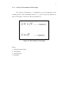
The velocity of ultrasound, c is formulated at a given temperature and a
constant pressure. The relationship between T, f, c and λ is given by Equation (1)
and (2). The Figure 2.1 below are the given formula [7]:
Figure 2.1: The formula of wavelength
Where
c = Material sound velocity
λ = Wavelength
T = Period of time
f = frequency
8
2.3.2
Wave Propagation
In many aspects, ultrasound is one the waves that can be found in the wave
spectrum such as microwave and it is very similar to light or other magnetic waves
form. The frequency of each type is different based on the propagation of waves in
different type of medium. The velocity also changed depends on the type of medium.
The concept of ultrasonic is same as light. It can be seen and refracted while going
through each medium to another medium. So, this will be effect the speed of sound
and refracted around a barrier. The energy also spreading just like a particles or dust
scattered below a light[8].
Ultrasound is a type of mechanical energy. It vibrates and can be penetrate
into any type of barrier such as liquid, gas and solid as well. Because of the
similarities characteristic between light and electromagnetic waves, they are just
same[9].
Basically, there are heats losses happen in the air. This is because the energy
is absorbed by the air and there is many factor that will give an effect to the losses of
heat such as molecular vibration modes, air viscosity heat conduction and
composition of air[10].
Figure 1.2: Illustration of the particle motion versus the direction of
wave
9
2.3.3
Speed of sound waves in air and water
There are different medium in this world which are solid, liquid and gas. So,
the velocity of sound is depends on each medium that it pass through. For example,
the velocity of sound is different between air and liquid but in term of speed, the
velocity of sound wave in water is faster than in air.
There are several factors that affect the velocity of sound which is the
temperature, pressure and the salinity. For example, the ultrasound waves was
disturbing by a particles of the high salinity of the sea water which is the particles is
quite scattered and sometimes absorb or reflect the sound waves.
The case of sea water because of the wavelength and the frequency of sound
waves are inversely proportional to the characteristic of ultrasound waves. The fact
is the lower the frequency signals, the longer the sound wavelength based on the
formula speed of sound as stated before. As a conclusion, a lower frequency can
travel long distance away without any losses of signals strength. For example,
ultrasound waves used for naval communication systems. It is developed by using a
low frequency and long wavelength so that it can be enhanced the communication
while submerging submarines[11].
10
CHAPTER 3
METHODOLOGY
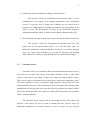
Chapter 3 describes the methodology of the projectbeginning with the
hardware implementationfollowed by software system development ultrasonic
tracking device.
11
3.1
Project Overview
The construction of an underwater ultrasonic tracking device consists of two
parts, which are hardware design and software design. Hardware design consists of
servo motor, Arduino UNO, HC-SR04 ultrasonic sensor, bread board and housing.
The ultrasonic sensor is used to detect or find out an object and send the signal back
to the receiver. Lastly, the object's position will be display by a processing display
window. Then, the servo will be rotate to detect an object within a limited range. By
using this technique, display window can display an object's positioned as long as the
object between the ranges of ultrasonic.
Software design is implemented by using an Arduino IDE and processing
development environment (PDE) software which are designed by using C
programming and C++ programming.
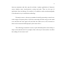
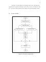
Figure 3.1: Overall design flow of underwater ultrasonic tracking device
12
The Figure 3.1 shows that the overall design of the system. The input of the
systemconsists of signal from ultrasonic sensor. The servo motor will rotate 45° until
135°. The result of object position will be display at the processing display window.
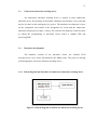
3.2
Project workflow
Figure 3.2: Flowchart of project flow
13
3.3
Underwater ultrasonic tracking device
An underwater ultrasonic tracking device is similar to other underwater
ultrasonic device development in the market. Hardware and software is two parts that
need to be done in this tracking device project. The hardware development is focus
on the component used which is the designation of circuit and the underwater
ultrasonic tracking device shape / casing. The software development is based on how
to coding the programming of ultrasonic sensor which is Arduino IDE and
processing PDE.
3.4
Hardware development
The hardware consists of the ultrasonic sensor, the Arduino UNO
microprocessor, servo sensor and ultrasonic HC-SR04 sensor. The project is starting
with designing the circuit for ultrasonic tracking device.
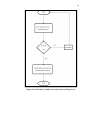
3.4.1
Block diagram and flowchart of underwater ultrasonic tracking device
Figure 3.3: Block diagram of underwater ultrasonic tracking device
14
Figure 3.4: Flowchart of underwater ultrasonic tracking device
15
3.4.2
Main components in the underwater ultrasonic tracking device
. The hardware of this project consists of an open-source hardware board
designed around an 8-bit Atmel AVR microcontroller. Current models feature a USB
interface, 6 analog input pins, as well as 14 digital I/O pins that can accommodate
various extension boards.
Arduino was introduced in 2005. The designer tried to provide an
inexpensive and easy way for students, professionals and hobbyists to create devices
that interact the environment by using sensors and actuator. It comes with a simple
integrated development environment (IDE) that runs on regular personal computers
and allows users to write programs for Arduino using C or C++.
3.5
Hardware
3.5.1
Arduino UNO
The Arduino UNO microcontroller is a single board microcontroller. Thus, it
is developed to make the beginner or expert easy to build interactive development
environments [12].
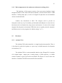
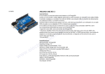
The Arduino UNO is a microcontroller based on the ATmega328. It consists
of 14 digital inputs / output pins, 6 analog inputs, a USB connector, a 16 MHz
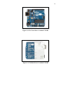
ceramic resonator, a power jack and a reset button. The Figures 3.5 and 3.6 show the
interface of Arduino UNO R3 microcontroller front and back.
16
Figure 3.5: The Front Part of Arduino UNO R3
Figure 3.6: The Back Part of Arduino UNO R3
17
3.5.2
Power
The good thing about Arduino UNO that power can be supplied by using a
USB connection comes from the laptop or external power supply from AC-DC
adapter or battery. The specification of external power supply or battery must be
followed the Arduino UNO power’s jack on the board which is about 2.1 mm centerpositive plug. Lastly, the connection of battery must be plug into the Gnd and Vin
pins[13]. The power pins are stated as follows:
Table 1: Power Pins of Arduino Board
Type of Pins
Description
Vin
The input voltage to the Arduino board which is it
opposed to 5v from the USB connection or other
regulated power source
5V
This pin outputs a regulated 5V from the regulator on the
board.
3v3
A 3.3 volt supply generated by the on-board regulator.
Maximum current draw is 50 mA
GND
Ground pins
IOREF
This pin on the Arduino board provides the voltage
reference with which the microcontroller operates. A
properly configured shield can read the IOREF pin
voltage and select the appropriate power source or enable
voltage translators on the outputs for working with the 5V
or 3.3V.
18
3.5.3
Memory Organization
Basically, an Arduino UNO microcontroller use ATmega328. The
ATmega328 has 32 KB. It also has 2 KB of SRAM and 1 KB of EEPROM (which
can be read and written with the EEPROM library). Figure 3.7 shows ATmega328
pin out.
Figure 3.7: ATmega328 Pin out Diagram
19
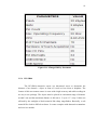
Figure 3.8: ATmega328 Key Parameter
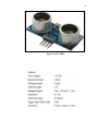
3.5.4
HC-SR04
The HC-SR04 ultrasonic sensor use ultrasound waves to determine the
distance of an obstacle / object in front of it such as bat vision or dolphins. The
feature of this non-contact sensor is come with a high accuracy and stable readings in
an easy to use package. The object must be placed in a minimum range of distance
around 2 cm and the maximum distance is 400 cm or 1" up to 13 " away. It does not
affected by the sunlight or black material like sharp rangefinders. Basically, a soft
material like cloth is difficult to detect. It comes complete with ultrasonic transmitter
and receiver module.
20
Figure 3.9: HC-SR04
21
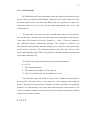
3.5.5
Basic Principle
HC-SR04 ultrasonic sensor transmitter emits the signal in one direction while
the time start to be calculated immediately. Ultrasonic waves will be dispersed in the
air and the signal will be come back after hit the object or any particles in front of it.
Lastly, the ultrasonic receiver will stop the timing immediately after receives the
reflected waves.
The ultrasonic waves has a velocity of sound about 340 m/s in air based on
the recorded time t. the time travel was taken between the transmitter to the distance
of the object. The formula of velocity of sound is s = 340t / 2. Those are known as
time difference distance measurement principle. This principle is related to the
measuring the time beginning from the emitting to the reflection of the signal when
hit the object or obstacle. The calculation based on the time and velocity of the
barrier and transmitter signal. Thus, the principle of ultrasonic distance measurement
is the same with radar [14].
The following are the ultrasonic distance measurement formula:
L=CxT
L - The measured distance
C - The ultrasonic spreading velocity in the air
T - Time (T is half the time of a transmitter to receive)
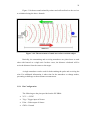
The ultrasonic sensor HC-SR04 is using a time of flight as measurement of
the properties of acoustic waves. it also known as "echo ranging" in the reflection
mode. A short burst of sound will be emitted by ultrasonic transmitter in a particular
direction. The pulse bounces off a target and return back after a time interval t. The
receiver records the length of this time interval, and calculates the distance travelled
r based on the speed of sound c:
r=c*t
22
Figure 3.10 shows sound emitted by emitter and reflected back to the receiver
as calculated using the above formula.
Figure 3.10: The movement of sound wave after reach the object
Basically, the transmitting and receiving transducers are placed next to each
other with housed as a single unit. In these cases, the distance calculated will be
twice the distance from the sensor to the target.
A single transducer can be used for both emitting the pulse and receiving the
echo. For additional information, it takes time for the transducer to change modes,
presenting a challenge to short-distance measurement.
3.5.6
Pin Configuration
The following are the pins provided on the HC-SR04:
VCC = +5VDC
Trig = Trigger input of Sensor
Echo = Echo output of Sensor
GND = Ground
23
Figure 3.11: HC-SR04 Pin Configuration
3.5.7
Operation
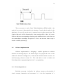
Figure 3.12 shows the time diagram for HC-SR04 ultrasonic sensor. This type
of sensor measure a pulse when HC-SR04 received a high pulse which is 5v equals
to 10 us. The ultrasonic sensor will be sent out 8 cycle of pulse at 40 kHz. It will
delay for a moment so that the ultrasonic sensor will received back the echo signal
with a high input 5v. The following are the way how to measure the width of Echo
pin and to obtain the distance:
Time = Width of Echo pulse, in uS (micro second)
Distance in centimeters = Time / 58
Distance in inches = Time / 148
Or the speed of sound, which is 340m/s
24
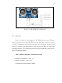
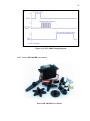
Figure 3.12: HC-SR04 Timing Diagram
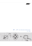
3.5.8
Power HD 3001HB servo motor
Power HD 3001HB Servo Motor
25
The power HD 3001HB servo motor is used to move the ultrasonic servo
within a rangeof degree from 45° until 135°. The figure 15 below shows the wire
connection of the power HD 3001 servo motor.
Figure 3.13: The wire connection
This type of servo motor has been used because of their specification which is
it made of plastic gear RC with 4.4kg.cm holding torque. Based on the project, it is
capable to hold the sensor housing to make it moveable. This type of servo is RC
servo motor. RC servo motor is a radio control which is converted electric from the
receiver back into movement and simply plug into a specific receiver channel. The
movement meaning that the servo will be only moving as much as the transmitter
stick on the device is moved. One of the advantage by using RC servo is the DC
brush motor is able to control its rotation angle. The following are the specifications
of the power HD 3001HB servo motor.
26
Table 2: The specification of servo motor
Size
Weight
Digital/Analog
Speed @ 6V
Stall Torque @6V
Speed @ 6V
Stall Torque @6V
Lead Length
Hardware Included
40.7 x 20.5 x 39.5mm
43g
Analog
0.12 sec/60°
4.4kg/cm
0.15 sec/60°
3.5kg/cm
11in (279.4mm)
Yes
27
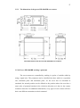
3.5.9
The dimension of the power HD 3001HB servo motor
The Dimension of the Power HD 3001HB Servo Motor
3.5.10 Power HD 3001HB working’s principle
The servo motors are controlled by sending it a pulse of variable width by
using a signal wire. The parameter can be classified into three which is a repetition
rate, minimum pulse and maximum pulse. As the servo has its constraint in
rotational, the neutral position can be defined as the position where the servo has a
same value of potential rotation in the clockwise direction as it does in the counter
clockwise direction. For additional information, every types of servo motor will have
their own different constraints on their rotational.
28
This servo motor is used a Pulse Width Modulation (PWM) which is the
angle of servo motor is determined by the duration of a pulse that is applied to the
signal wire. In every 20 ms the servo is expected to see a pulse sent to them. The
length of the pulse will be determined by motor turning which is how far it turns.
However, the exact correspondence between pulse width and servo varies from one
servo manufacturer to another. The pulse of 1.5 ms is not an exact value to stay in
neutral or middle position[15].
3.6
Software implementation
Software implementation is designing a suitable algorithm to calculate
distance for detecting object in the limited region. To program the code of this
underwater ultrasonic tracking device, it must use the Arduino software version 1.5.4
and Processing software version 2.2.1. The code which is used in Aduino and
Processing software programming based on C++ programming.
3.6.1
Processing Software
Basically, processing is related to the software concept to the principle of
visual concepts, interaction and movement. It is also the integration of a
29
programming language environment, development, and teaching methods into a
unified system. Processing was created for processing fundamentals of computer
programming within the context of visual and also as a software sketchbook. Besides
that, it is also used as prototype manufacturing, an output and production.
The processing language is specifically designed to generate and modify
images especially for this project. It can be achieved the clarity and advanced
features. All the beginners can write their own programs and the advanced user also
can employ and write libraries with additional function. The system provides many
computer graphics and interaction techniques including image processing, vector
drawing, colour models, mouse and keyboard events, object-oriented programming
and network communication,. The libraries are capable to generate sound,
send/receive data in diverse formats, and to import or export 2D and 3D file formats
[16].
Figure 3.14: Processing Display Window
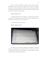
30
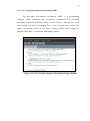
3.6.2
Processing Development Environment (PDE)
The processing development environment (PDE) is a programming
languages, online community and development environment. The processing
development environment (PDE) consists of a text console, a message area, a text
editor writing code, tabs for managing files, a series of menus and a toolbar with
buttons for common actions. It will show a display window when running the
program. The Figure 3.15 shows the PDE display window.
Figure 3.15: Processing Development Environment Display Window
31
CHAPTER 4
RESULT AND DISCUSSION
4.1
Introduction
Chapter four is about the experiments carried out to get the result. The
experiment is the limitation of ultrasonic sensor and to display the object position at
the processing display window.
4.2 Tracking system
4.2.1
Experimental in air
The ultrasonic HC-SR04 was used to detect the object or obstacle in the free
space (air). As additional information, when ultrasonic sensor sent the signal from
transmitter to the barrier, the echo will be reflected back to the receiver so that it will
convert to the image processing to view the obstacle’s position. The signal’s
frequency sent by transmitter is 40 kHz. So it is able to go through air easily. Then
the data will be recorded on the screen based on the distance away from the object
and also the degrees of rotational. Figure 18 shows an object detected due to signal
bounce back to the receiver.
The distance between the obstacle and ultrasonic sensor in can be determined
by using the formula distance=time/58. It also shows the degree of rotation for each
32
distance sensed by ultrasonic due to the rotation of servo motor within the ranges of
45° until 135° by using the formula angle = float(Theta) /180 * pi.
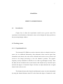
Figure 4.1: The data recorded based on the distance of object in the air
Table 3: Result of sensor detected and measures distance
Distance Measurement (cm)
Sensor Detected (cm)
5
5
10
10
15
15
20
20
25
25
33
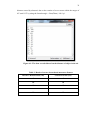
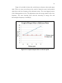
Figure 4.2: Graph of sensor detected distance vs distance measures
Table 3 and Figure 4.2 show the differences between ultrasonic sensor
measurement and the actual measurement between the object and ultrasonic sensor.
There are no error between the result of ultrasonic sensor and measured values
because of ultrasonic transmit signal in the air is smooth. This project is limited by
the frequency of ultrasonic sensor and the low cost of material. Hence, it only shows
the transmitted signal with a limited range of distance and the value is reliable.
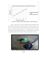
Figure 4.3: Hardware implementation (HC-SR04 sensor) for tracking
system
34
Figure 4.3 shows the hardware implementation of a tracking system. The
ultrasonic sensor was designed to be waterproof. The element being used was food
wrapping as a cover of ultrasonic transmitter and receiver. This is due to the dead
zone of ultrasonic sensor. Dead zone can be called as blind zone. Basically,
ultrasonic sensor have a "dead zone" in front of them which is the object cannot be
detected by transmitter signal. This is because they deflected the wave back before
the receiver signal is operational. In other word, the resonance from the transmitter
signal is force the receiver signal to pause a moment before starting to listen for the
echo.
The LED on the above picture show that the ultrasonic HC-SR04 sensor
working on the food wrapping. Even though the transmitter and receiver are both
were cover by food wrapping but the signal still can be transmit and receive since the
object in front of it. The following are the dead / blind zone of ultrasonic sensor.
35
4.2.2
Experimental in water
Sound waves are one of the compression wave based on the audible
spectrum. As human being, we are only using a range of frequency about 20 Hz up to
20 kHz. Besides that, marine life has their own range of frequency which is more
than 20 kHz. Sound outside the human hearing range of frequencies also known as
infrasound which is below 20 Hz and ultrasound which is above 20 kHz [17].
This experimental was carried out by immersing the ultrasonic HC-SR04
covering with food wrapping into the water. As a result, a food wrapping can
withstand with the water and there is no leaking either at the food wrapping or
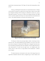
housing. The Figure 4.4 shows that hardware implementation for housing.
Figure 4.4: Hardware implementation for housing
The housing made up from an environmental casing. This is due to the
rusting factor. An environmental casing is one way to reduce the environment
pollution and also it can be used for many times. For the first attempt to make
housing, perspex was choose because of the endurance is high quality but at the same
time it is difficult to produce. In additional, the project is focus more to the low cost
36
material and environmental aspect. The Figure 4.5 shows the housing made up from
prespex.
This type of housing still cannot achieve the requirement because of leakage
in the housing. The prespex was glued with a hot glue gun so that the water cannot
pass through the housing. The first attempt was failed and it needs to be re-do by
using others alternative. It also gives an effect to the reading of ultrasonic HC-SR04
sensor to emit the signal because the glue was scattered and close the transmitter and
receiver. The reading of distance is not achieves the consistence value.
Figure 4.5: Hardware implementation for first attempt
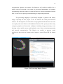
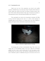
The Figure 4.6 shows the processing display window is detecting an object
inside the water. The signal transmitted by the transmitter is not get an exact value
due to the low frequency of ultrasonic HC-SR04 sensor. It happens only in the water
due to the different propagation paths. The transmitted / reflected signal will not have
same characteristics as a pulse near the signal source. An elongated pulse from
seismic sources is often occurs at a long distances when transmission / reflection
process happen.
The object detection is only placed on the centre of the image because the
signal has its limitation inside the water by using this type of sensor. Based on the
37
datasheet of HC-SR04 ultrasonic sensor, the frequency of ultrasound is fixed to 40
kHz. The sensor is unable to increase the voltage due to the fixed voltage. In theory,
the power of signal transmitted can be increase and it possible to penetrate the solid
medium by amplified the voltage supplier.
Figure 4.6: The processing display window showing the detection object
Figure 4.7: The distance value of ultrasonic sensor
38
Figure 4.7 shows the limitation of ultrasonic sensor when the signal is
transmitted but with a short range of distance. This is because the coding of
ultrasonic sensor has been changed. The formula of speed of sound is not exactly like
the datasheet’s formula but the constant value of the formula was changed to get the
real value. The exact speed of sound formula:
Distance = distance1 / 58
As additional information, the wavelength of a sound between air and water
is equal. It can be divided into two types of sound wave which is 20 KHz where 75 m
long in the water and 20 Hz where 17 m long in the air.
The formula being used as shown below:
Distance = distance1 / 1500
Figure 4.8: The value of distance before calibrating the resolution
The Figure 4.8 above shows the resolution before calibration. The resolution
of distance is too high because of the smallest change of constant value in the speed
of sound formula. By putting a large number of constant values so that the
resolutionbecome smaller as shown in figure 24.
39
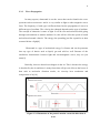
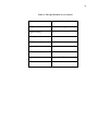
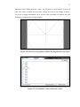
Figure 4.9 and table 4 shows the result between reference object and output
value. There are some errors between the result of ultrasonic sensor and measured
values due to the low frequency of the ultrasonic sensor. The errors happen because
of the inhomogeneous waves. The phenomena cause the energy transfer with a low
frequency. The cases showing itself with the increasing of energy flux and
decreasing the frequency of sound[18].
Figure 4.9: Graph of output value vs reference point
40
Table 4: The result of reference point and output value
4.2.3
Reference point (cm)
Output value (cm)
7
7
9
7
11
7
13
7
15
7
Rotational system
The energy of electromagnetic wave will be slowed down when it pass
through into the water. This is because the ability of the sound wave has a limited
range of distance. This is happen when the signal inferred each other. To get the
exact value, they must use a special specification of the underwater sound waves
equipment.
As an alternative way, the rotational of the project is limited from 45° until
135°. The first attempt was to put some degree so that the ultrasonic sensor can
detect the object inside the water. In theory, the movement of water give an effect to
the signal of ultrasonic sensor due to the particles of water itself does not synchronise
each other. The Figure 4.10 shows that the rotational ultrasonic sensor with a smooth
water propagation.
41
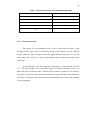
Figure 4.10: The rotation of ultrasonic sensor in the water
45°
45°
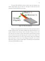
Figure 4.11: The limitation of servo motor
Figure 4.11 shows that the limitation of servo motor can be implemented in
this project. The red line is the showing that 45° until 135°. So the object detection
image will be display within a range of the limitation only.
42
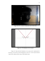
4.3
Overall system design
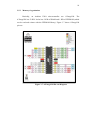
Figure 4.12 shows the schematic diagram of this project. HC-SR04 ultrasonic
sensor, the connection of digital input Port 8 is for trigger pin while digital input port
7 is for echo respectively. The connection of the servo motor is at the digital input
port 9.
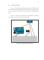
Figure 4.13 shows the overall hardware of circuit diagram. The ultrasonic
sensor and servo motor are connected to the Arduino UNO.
Figure 4.12: Schematic diagram of project
43
Figure 4.13: The overall hardware of circuit diagram
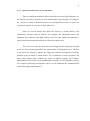
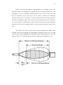
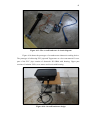
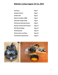
Figure 4.14 shows the prototype of an underwater ultrasonic tracking device.
The prototype is built using PVC pipe and Tupperware as a low cost material. Lower
part of the PVC pipe consists of ultrasonic HC-SR04 with housing. Upper part
consists of Arduino UNO, servo motor and circuit with housing.
Figure 4.14: Overall hardware design
44
CHAPTER 5
CONCLUSION
5.1
Introduction
Chapter five concludes the whole project of an ultrasonic underwater tracking
device. Several recommendations for the future work are stated as well.
5.2
Conclusion
As a conclusion, the projectincludes the combination of ultrasonic sensor,
servo motor, and Arduino UNO R3 for tracking object in the water. The development
environment consists of two types which are Arduino IDE and Processing (PDE).
Two main objectives which isto find object in the water and to display the position of
an object by using a processing software is successfully implemented even though
the signal of ultrasonic sensor did not get exact value which is the range of signal
transmitted is around 7 cm.
The hardware and software of the project had been successfully implemented
andworked as the requirements. The prototype of an underwater ultrasonic tracking
device is built and the function meets some of the objectives of this project.
45
5.3
Future work
Several future planning are suggested and recommended so that the project
can be improved. The accuracy of the obstacle detection can be increased. Therefore,
the frequency of the ultrasonic sensor must be higher than frequency of water and the
rotational of servo motor should be improved. The servo motor can be adjusted to
detect fast moving objects. Moreover, the degree of rotational can be increase to
360°.
The processing image can be improved by putting a distance of object’s
detection. The ultrasonic sensorshould be able to capture distance precisely.
46
CHAPTER 6
PROJECT MANAGEMENT
6.1
Introduction
The project management is very important as a smoothness of the project
planning. It is consists of the overall planning control and coordination of a project,
from inception through to completion. The process is about the responsibilities for all
phase of a project. They are combined all the phase within one multi-disciplinary
function[19].
6.1.1
Project schedule
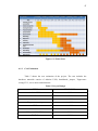
The Figure 6.1 shows the Gantt chart for both semester 1 and semester 2. For
semester 1, the project is focus on the research of the fabrication. Ultrasonic sensor
and servo motor are studied to get the function and design. For semester 2, the
project is focus on the programming on tracking system including IDE and PDE.
After that, the circuit for the design is built up. The prototype of a project needs to
test and calibrate to ensure the requirement achieve the objective.
47
Figure 6.1: Gantt chart
6.1.2
Cost Estimation
Table 5 shows the cost estimation of the project. The cost includes the
hardware materials consist of Arduino UNO, breadboard, jumper, Tupperware
casing, PVC, servo motor and ultrasonic.
Table 5: Project Budget
ITEM
PRICE (RM)
Arduino UNO
40.00
Breadboard
7.90
jumper
Available
Tupperware casing
Available
PVC
Available
Servo Motor
39.00
Ultrasonic HC-SR04
39.00
TOTAL
125.90
48
REFERENCES
[1]
Mason,
W.P.
Sonics
and
Ultrasonics:
Early
History
and
Applications.Ultrasonics Symposium in 1976.
[2]
M.Teshingwara, F.S., H. Teramoto, high resolution and fast responce
range finder for industrial use in air. OMRON Tateisi Electronics Co.
1989.
[3]
Chou, T.N.,M. J. Usher,An integrated ultrasonic system for detection,
Macmillan Publishers Ltd, 1985.
[4]
Kazuhiro, T.F, underwater imaging system using acoustic holography.
2000.
[5]
M.Ashraf,
J.L.,
Underwater
Object
recognition
technique
using
ultrasonics. 1994.
[6]
Xie, S., et al., Detection and Tracking of Underwater ObjectBased on
Forward-Scan Sonar. 1985.
[7]
Abidin, M.S.b.Z., Ultrasonic Fuel Tank Level Measuring System. 2008.
[8]
Elastic Wave Propagation and Associated Phenomena, in Ultrasonics,
CRC Press. p. 27-100. 2011.
[9]
Pain, H.J., The Physics of Vibrations and Waves. 5th ed. Chichester, New
York: Wiley. 1999.
[10]
Lindsay, K., Ultrasonic Sensors, in Control and Mechatronics, CRC Press.
p. 1-15. 2011.
49
[11]
Lerner, K.L., Sound Transmission in the Ocean, in water encylopedia science and issues.
[12]
O.s.A.P.R. Official slogan". Arduino Project.2013.
[13]
http://arduino.cc/en/Main/ArduinoBoardUno.
[14]
Guide, H.-S.U.M.U., HC-SR04 Ultrasonic Module User Guide
[15]
Technologies, C., HD-3001HB/1501MG RC Servo Motor User's Manual in
v1.0. May 2014.
[16]
Fry, C.R.a.B., Processing: A Programming Handbook for Visual
Designers and Artists. Published August 2007.
[17]
Producers, I.A.o.O.G., Fundamentals of underwater sound. May 2008.
[18]
Godin, O.A., Transmission of Low-Frequency Sound through the Waterto-Air Interface. September 6, 2006.
[19]
Taylor & Francis, What is Project Management?, in Project Management
Framework. 2003.
50
APPENDIX A
Tracking System Coding
#define ECHOPIN 7
// Pin to receive echo pulse
#define TRIGPIN 8
#include <Servo.h>
Servo myservo; // create servo object to control a servo
intpos = 0; // variable to store the servo position
void setup()
{
Serial.begin(9600);
myservo.attach(9); // attaches the servo on pin 9 to the servo object
pinMode(3,OUTPUT);
pinMode(12,OUTPUT);
pinMode(13,INPUT);
pinMode(ECHOPIN, INPUT);
pinMode(TRIGPIN, OUTPUT);
}
void Print (int R , int T)
{
Serial.print(R);Serial.print(", ");
Serial.print(T);Serial.println(".");
delay(100);
}
float Distance ()
{
51
digitalWrite(TRIGPIN, LOW);
delayMicroseconds(2);
digitalWrite(TRIGPIN, HIGH);
delayMicroseconds(10);
digitalWrite(TRIGPIN, LOW);
// Distance Calculation
float distance = pulseIn(ECHOPIN, HIGH);
distance= distance/1200;
return(distance);
}
void loop()
{
myservo.write(45); // tell servo to go to position in variable 'pos'
delay(2000);
for(pos = 45; pos <= 135; pos += 3) // goes from 45 degrees to 135 degrees
{ // in steps of 1 degree
myservo.write(pos); // tell servo to go to position in variable 'pos'
Print(Distance() , pos);
delay(10); // waits 15ms for the servo to reach the position
}
delay(1000);
for(pos = 135; pos>= 45; pos-=3) // goes from 135 degrees to 45 degrees
{
myservo.write(pos); // tell servo to go to position in variable 'pos'
Print(Distance() , pos);
delay(10); // waits 15ms for the servo to reach the position
}
}
52
APPENDIX B
Image Processing Coding
importprocessing.serial.*;
Serial port;
Serial port2;
String data = "";
String Radius = "";
String Theta = "";
int index = 0;
float distance = 0;
float angle = 0;
float pi = 22.0/7;
void setup()
{
size(1000,1000);
background(255,255,255);
ellipse(500,500,1000,1000);
line(500,0,500,1000);
line(0,500,1000,500);
line(500,500,1000,0);
line(500,500,0,0);
port = new Serial(this, "COM3", 9600);
port.bufferUntil('.');
}
void draw()
{
53
}
voidserialEvent(Serial port)
{
data = port.readStringUntil('.');
data = data.substring(0, data.length() - 1);
index = data.indexOf(",");
Radius = data.substring(0, index);
Theta = data.substring (index+1 ,data.length());
translate(500,500);
point (0,0);
distance = float(Radius);
angle = float(Theta) /180 * pi;
fill(30,200,30);
ellipse(distance * cos(angle) , -1 * distance * sin(angle) , 5,5);
}