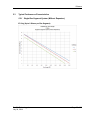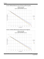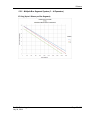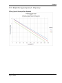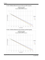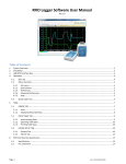
1
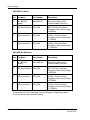
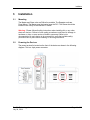
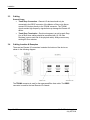
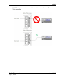
IMC-BHx-AC Industrial Media Converter Ethernet over Belden 9463 “Blue Hose” July 24, 2014 INSTALLATION GUIDE IMC-BHx-AC Installation Guide Your Feedback Please We always want you to feel that you made the right decision to use our products. If you have suggestions, comments, compliments or complaints about our products, documentation, or support, please write or call us. How to Contact Us ProSoft Technology 5201 Truxtun Ave., 3rd Floor Bakersfield, CA 93309 +1 (661) 716-5100 +1 (661) 716-5101 (Fax) www.prosoft-technology.com [email protected] Copyright © 2014 ProSoft Technology, Inc., All rights reserved. IMC-BHx-AC Installation Guide July 24, 2014 ProSoft Technology® Product Documentation In an effort to conserve paper, ProSoft Technology no longer includes printed manuals with our product shipments. User Manuals, Datasheets, Sample Ladder Files, and Configuration Files are provided on the ® enclosed DVD in Adobe Acrobat Reader file format (.PDFs). These product documentation files may also be freely downloaded from our web site: www.prosoft-technology.com ProSoft Technology, Inc. July 24, 2014 Page 3 of 30 IMC-BHx-AC Installation Guide Page 4 of 30 ProSoft Technology, Inc. July 24, 2014 IMC-BHx-AC Installation Guide Contents Your Feedback Please ........................................................................................................................ 3 How to Contact Us .............................................................................................................................. 3 ® ProSoft Technology Product Documentation .................................................................................... 3 1 Start Here 1.1 1.2 1.3 2 Master........................................................................................................................ 8 Slave.......................................................................................................................... 8 Repeater .................................................................................................................... 8 Before You Begin 2.1 3 Installation 3.5.1 4 4.1 11 Mounting .................................................................................................................. 11 Powering the Devices .............................................................................................. 11 Cabling .................................................................................................................... 12 Cabling Location & Examples ................................................................................. 12 Using a Repeater .................................................................................................... 17 Using Repeaters on the Network ............................................................................ 17 LED Functionality 5 9 Package Content ....................................................................................................... 9 3.1 3.2 3.3 3.4 3.5 19 Remote I/O Serial Status LEDs ............................................................................... 19 Reference 5.1 5.2 5.3 5.3.1 5.3.2 5.3.3 6 7 21 Device Specifications .............................................................................................. 21 Maximum System Specifications ............................................................................ 22 Typical Performance Characteristics ...................................................................... 23 Single Bus Segment System (Without Repeaters) ................................................. 23 Multiple Bus Segment System (1 – 4 Repeaters) ................................................... 25 Multiple Bus Segment System (5 – 8 Repeaters) ................................................... 27 Support, Service & Warranty 29 Contacting Technical Support ........................................................................................................... 29 6.1 Warranty Information ............................................................................................... 30 ProSoft Technology, Inc. July 24, 2014 Page 5 of 30 Start Here 1 Start Here The IMC-BHx-AC family of media converters allow for the simultaneous multidrop transport of EtherNet/IP™ and Remote I/O data over repurposed Belden 9463 “Blue Hose” cabling. Each Master (IMC-BHM-AC) and Slave (IMC-BHS-AC) module supports Remote I/O networks operating at 57.6K or 115.2K baud rates. The modules are automatically configured to the baud rate of the remote I/O data. Three Ethernet ports are also available on the Master and Slave modules allowing up to three Ethernet devices to be connected to the media converter before a switch is required. Both EtherNet/IP™ and Remote I/O data are simultaneously encoded by the Master or Slave module into a modulated broadband signal that is transported via a baseband subcarrier over the repurposed “Blue Hose” cabling. The complex waveform carrying EtherNet/IP and Remote I/O data is then received by the Master or Slave module and the original EtherNet/IP and Remote I/O data is decoded. ProSoft Technology, Inc. July 24, 2014 Page 7 of 30 Start Here Additionally, Repeater modules (IMC-BHR-AC) can be used to transport the combined EtherNet/IP and Remote I/O signal even further for applications that require longer lengths of “Blue Hose” cable. 1.1 Master Each network requires one Master device. The device is installed within 25 feet of the controller and provides: 3 Ethernet ports (expandable via switch) 1 RIO Trunk port 1 RIO Drop port Note: The Trunk line requires a 150 Ohm resistor at each end. Each drop line also requires a 150 Ohm resistor. 1.2 Slave Each network requires at least one Slave device. Slaves communicate with the RIO nodes and provide: 3 Ethernet ports 1 RIO Trunk port 1 RIO Drop port Up to eight RIO nodes within 1000 feet may be daisy-chained off the drop line. 1.3 Repeater Repeaters are required when there are more than six Media Converter Slaves and/or the maximum trunk cable length exceeds the maximum distance specified in the table at the end of this guide. Page 8 of 30 ProSoft Technology, Inc. July 24, 2014 Before You Begin 2 Before You Begin Consider the following points before installing the module: 2.1 Each system requires one Master unit connected to the PLC Each system can have up to six Slave units before a Repeater is required Each Slave unit can have up to eight Remote I/O nodes connected to it A Repeater is required if the overall network distance exceeds 1300 to 1750 feet (see Performance Chart at the end of this guide) Package Content The following tables show the components including with IMC-BHx-AC modules. Ensure that all items are present before starting the installation. IMC-BHM-AC (Master) Qty Part Name Part Number Description 1 IMC-BHM-AC Module IMC-BHM-AC Ethernet over Blue Hose Industrial Media Converter 4 150 Ohm Resistors 102-1500 RES 150 Ohm Term Block Pluggable, GRN, Screw Flange (144-0050) 2 3-pin Connectors 357-0149 CONN, 3 Pos Term Block Pluggable, GRN, Screw Flange (173-0008) 1 4-pin Connectors 357-0148 CONN, 4 Pos Term Block Pluggable, GRN, Screw Flange (173-00009) 1 ProSoft Solutions DVD DVD-001 Contains documentation for the IMC-BHx-AC ProSoft Technology, Inc. July 24, 2014 Page 9 of 30 Before You Begin IMC-BHS-AC (Slave) Qty Part Name Part Number Description 1 IMC-BHS-AC Module IMC-BHS-AC Ethernet over Blue Hose Industrial Media Converter 4 150 Ohm Resistors 102-1500 RES 150 Ohm Term Block Pluggable, GRN, Screw Flange (144-0050) 2 3-pin Connectors 357-0149 CONN, 3 Pos Term Block Pluggable, GRN, Screw Flange (173-0008) 1 4-pin Connectors 357-0148 CONN, 4 Pos Term Block Pluggable, GRN, Screw Flange (173-00009) Qty Part Name Part Number Description 1 IMC-BHR-AC Module IMC-BHR-AC Ethernet over Blue Hose Industrial Media Converter 4 150 Ohm Resistors 102-1500 RES 150 Ohm Term Block Pluggable, GRN, Screw Flange (144-0050) 2 3-pin Connectors 357-0149 CONN, 3 Pos Term Block Pluggable, GRN, Screw Flange (173-0008) 1 4-pin Connectors 357-0148 CONN, 4 Pos Term Block Pluggable, GRN, Screw Flange (173-00009) IMC-BHR-AC (Repeater) Please contact ProSoft Technology Technical Support for replacement parts if any of the above components are missing. Page 10 of 30 ProSoft Technology, Inc. July 24, 2014 Installation 3 Installation 3.1 Mounting The Master and Slave units are DIN-rail mountable. The Repeater units are Panel Mount. The Master must be located near the PLC. The Slaves should be located in the vicinity of the Remote I/O nodes. Warning: Please follow all safety instructions when installing this or any other electronic devices. Failure to follow safety procedures could result in damage to hardware or data, or even serious of death to personnel. Refer to the documentation for each device to be connected to verify that suitable safety procedures are in place before installing or servicing this device. 3.2 Powering the Devices The power terminal is located on the front of the device as shown in the following diagram. This is a 4-pin power connector. ProSoft Technology, Inc. July 24, 2014 Page 11 of 30 Installation 3.3 Cabling General Usage Trunk /Drop Connection – Remote I/O devices should only be connected to the DROP connector of the Master or Slave units. Never connect RIO devices directly to the TRUNK connector. The TRUNK signals contain high-frequency signals that may damage the Remote I/O device. Trunk/ Drop Termination – Each trunk segment, as well as each Drop Line of Blue Hose cabling should be terminated with (2) 150 Ohm Resistors (one on each end of the physical cable). Always remove any existing 82 Ohm resistors. 3.4 Cabling Location & Examples There are two Remote I/O connectors located at the bottom of the device as shown in the following diagram. The TRUNK connector is used for the repurposed Blue Host cable. The DROP connector is used for the local Remote I/O network. Page 12 of 30 ProSoft Technology, Inc. July 24, 2014 Installation Do NOT attempt to connect a remote I/O network device to a Master or Slave Trunk connector. ProSoft Technology, Inc. July 24, 2014 Page 13 of 30 Installation The following diagram shows the cabling configuration between a PLC-5 and RIO devices: Page 14 of 30 ProSoft Technology, Inc. July 24, 2014 Installation The device also provides three RJ-45 Ethernet connectors located on the front of the unit. These are used for the CLX EtherNet/IP™ controllers. ProSoft Technology, Inc. July 24, 2014 Page 15 of 30 Installation Multipoint Example This example shows three Slaves connected to a single Master. Page 16 of 30 ProSoft Technology, Inc. July 24, 2014 Installation 3.5 Using a Repeater The number of Slave units and nodes dictate the usage of a Repeater. Refer to the Specification and Performance Charts. 3.5.1 Using Repeaters on the Network Repeaters should be used in a system when any of the following conditions exist: More than six slaves are being used. More than 1750 feet of Blue Hose Trunk will be used in an Ethernet-only system. More than 1300 feet of Blue Hose Trunk will be used in an Ethernet and Remote I/O system. ProSoft Technology, Inc. July 24, 2014 Page 17 of 30 Installation Page 18 of 30 ProSoft Technology, Inc. July 24, 2014 LED Functionality 4 LED Functionality 4.1 Remote I/O Serial Status LEDs Trunk Status LED = Trunk – (Green, Yellow, or Red). Monitors the status of the trunk connection between each Master, Slave, or Repeater. RIO Drop Status LED = DROP - (Green, Yellow, or Red). Monitors the status of local Remote I/O connections between Remote I/O nodes Color Status Description Green Remote I/O Good (RIO Traffic Active) Remote I/O Signal Detected. (Immediate LED response from Yellow to Green) Integration of RIO serial data wave for is acceptable Yellow Remote I/O Loss (RIO Timed Out) No Valid Remote Signaling Detected. (Analysis window time up to 30 seconds) Red Remote I/O Error (RIO Squelched) No Remote I/O Signal Detected. (Red error indicates RIO signal health is out of bounds) Integration of RIO serial data waveform is outside of acceptable operating range. Squelch activated causes module to stop all transmission into Trunk and Drop when Red. . ProSoft Technology, Inc. July 24, 2014 Page 19 of 30 LED Functionality 50/60HZ POWER N L1 120/240 VOLTS AC G Trunk TRUNK LED 1 SH 2 TRUNK PORT 1 TRUNK CONNECTOR PORT 2 ETHERNET 1 SH 2 DROP PORT 3 DROP CONNECTOR Drop DROP LED BOTTOM FRONT Page 20 of 30 ProSoft Technology, Inc. July 24, 2014 Reference 5 Reference 5.1 Device Specifications IMC-BHM-AC (Master) Dimensions: Weight: Power: Operating Temp: Storage Temp: Humidity: LEDs (G,Y, R) Ethernet Ports: Cabling Type (Trunk Drop): Ethernet Bandwidth: Remote I/O Baud Rates: Din Rail Mountable: 8.3 x.2.7 x 4.3 in. (2.10 x 67.6 x 108.7mm) 1 lb 15 oz. (0.879 kg) 120/240 VAC (-15%/+10%) 60/50 Hz 2 Amps Max (5 Watt Nom) 0°C to +60°C -40°C to +80°C 10% to 90% (non-condensing) Trunk Status (Tri0Color), Drop Status (Tri-Color) Local 3 Port 10/100 Ethernet RJ-45 Belden 9463 “Blue Hose” 1-4 Mbps (20-40 Mbps Peak) 57.6K and 115.2K Yes IMC-BHS-AC (Slave) Dimensions: Weight: Power: Operating Temp: Storage Temp: Humidity: LEDs (G,Y, R) Ethernet Ports: Cabling Type (Trunk Drop): Ethernet Bandwidth: Remote I/O Baud Rates: Din Rail Mountable: ProSoft Technology, Inc. July 24, 2014 8.3 x.2.7 x 4.3 in. (2.10 x 67.6 x 108.7mm) 1 lb 15 oz. (0.879 kg) 120/240 VAC (-15%/+10%) 60/50 Hz 2 Amps Max (5 Watt Nom) 0°C to +60°C -40°C to +80°C 10% to 90% (non-condensing) Trunk Status (Tri0Color), Drop Status (Tri-Color) Local 3 Port 10/100 Ethernet RJ-45 Belden 9463 “Blue Hose” 1-4 Mbps (20-40 Mbps Peak) 57.6K and 115.2K Yes Page 21 of 30 Reference IMC-BHR-AC (Repeater) Dimensions: Weight: Power: Operating Temp: Storage Temp: Humidity: Cabling Type (Uplink Trunk/Downlink Trunk): Ethernet Bandwidth: Remote I/O Baud Rates: Din Rail Mountable: 5.2 13.5 x.11 x 5.5 in. (342.9 x 279.4 x 139.7 mm) 11 lbs 6 oz. (5.159 kg) 120/240 VAC (-15%/+10%) 60/50 Hz 4 Amps Max (10 Watt Nom) 0°C to +60°C -40°C to +80°C 10% to 90% (non-condensing) Belden 9463 “Blue Hose” 1-4 Mbps (20-40 Mbps Peak) 57.6K and 115.2K Yes Maximum System Specifications Single Trunk Segment Systems (Without Repeaters) Number of RIO devices on Drop: Drop Overall Length: Number of Slaves on Trunk: Trunk Overall Length (Ethernet and Remote I/O: Trunk Overall Length: 8 1000 feet 8 1300 feet 1600 feet Multiple Trunk Segment Systems (With Repeaters) Number of RIO devices on Drop: Drop Overall Length: Number of Slaves on Trunk: Trunk Overall Length (Ethernet and Remote I/O: Trunk Overall Length: Page 22 of 30 8 1000 feet 6 1200 feet 1750 feet ProSoft Technology, Inc. July 24, 2014 Reference 5.3 Typical Performance Characteristics 5.3.1 Single Bus Segment System (Without Repeaters) IP Only (Up to 8 Slaves per Bus Segment) ProSoft Technology, Inc. July 24, 2014 Page 23 of 30 Reference IP with 57.6K Baud Remote I/O (Up to 8 Slaves per Bus Segment) IP with 115.2K Baud Remote (Up to 8 Slaves per Bus Segment) Page 24 of 30 ProSoft Technology, Inc. July 24, 2014 Reference 5.3.2 Multiple Bus Segment System (1 – 4 Repeaters) IP Only (Up to 6 Slaves per Bus Segment) ProSoft Technology, Inc. July 24, 2014 Page 25 of 30 Reference IP with 57.6K Baud Remote I/O (Up to 6 Slaves per Bus Segment) IP with 115.2K Baud rate Remote I/O (Up to 6 Slaves per Bus Segment) Page 26 of 30 ProSoft Technology, Inc. July 24, 2014 Reference 5.3.3 Multiple Bus Segment System (5 – 8 Repeaters) IP Only (Up to 6 Slaves per Bus Segment) ProSoft Technology, Inc. July 24, 2014 Page 27 of 30 Reference IP with 57.6K Baud Remote I/O (Up to 6 Slaves per Bus Segment) IP with 115.2K Baud Remote I/O (Up to 6 Slaves per Bus Segment) Page 28 of 30 ProSoft Technology, Inc. July 24, 2014 Support, Service & Warranty 6 Support, Service & Warranty Contacting Technical Support ProSoft Technology, Inc. (ProSoft) is committed to providing the most efficient and effective support possible. Before calling, please gather the following information to assist in expediting this process: Product Version Number System architecture Network details If the issue is hardware related, we will also need information regarding: Module configuration and associated ladder files, if any Module operation and any unusual behavior Configuration/Debug status information LED patterns Details about the serial, Ethernet or fieldbus devices interfaced to the module, if any. Note: For technical support calls within the United States, an after-hours answering system allows 24-hour/7-days-a-week pager access to one of our qualified Technical and/or Application Support Engineers. Detailed contact information for all our worldwide locations is available on the following page. ProSoft Technology, Inc. July 24, 2014 Page 29 of 30 Support, Service & Warranty Internet Web Site: www.prosoft-technology.com/support E-mail address: [email protected] Asia Pacific (location in Malaysia) Tel: +603.7724.2080, E-mail: [email protected] Languages spoken include: Chinese, English Asia Pacific (location in China) Tel: +86.21.5187.7337 x888, E-mail: [email protected] Languages spoken include: Chinese, English Europe (location in Toulouse, France) Tel: +33 (0) 5.34.36.87.20, E-mail: [email protected] Languages spoken include: French, English Europe (location in Dubai, UAE) Tel: +971-4-214-6911, E-mail: [email protected] Languages spoken include: English, Hindi North America (location in California) Tel: +1.661.716.5100, E-mail: [email protected] Languages spoken include: English, Spanish Latin America (Oficina Regional) Tel: +1-281-2989109, E-Mail: [email protected] Languages spoken include: Spanish, English Latin America Tel: +52-222-3-99-6565, (location in Puebla, Mexico) E-mail: [email protected] Languages spoken include: Spanish Brasil (location in Sao Paulo) 6.1 Tel: +55-11-5083-3776, E-mail: [email protected] Languages spoken include: Portuguese, English Warranty Information For complete details regarding ProSoft Technology’s TERMS & CONDITIONS OF SALE, WARRANTY, SUPPORT, SERVICE AND RETURN MATERIAL AUTHORIZATION INSTRUCTIONS please see the documents on the Product DVD or go to www.prosoft-technology/warranty Documentation is subject to change without notice. Page 30 of 30 ProSoft Technology, Inc. July 24, 2014