1
Dialogic® DSI Signaling Servers
SS7G41 Hardware Manual
www.dialogic.com
Copyright and Legal Notice
Copyright © 2012-2013. Dialogic Inc. All Rights Reserved. You may not reproduce this document in whole or in part without permission in
writing from Dialogic Inc. at the address provided below.
All contents of this document are furnished for informational use only and are subject to change without notice and do not represent a
commitment on the part of Dialogic Inc. and its affiliates or subsidiaries ("Dialogic"). Reasonable effort is made to ensure the accuracy of the
information contained in the document. However, Dialogic does not warrant the accuracy of this information and cannot accept responsibility for
errors, inaccuracies or omissions that may be contained in this document.
IINFORMATION IN THIS DOCUMENT IS PROVIDED IN CONNECTION WITH DIALOGIC® PRODUCTS. NO LICENSE, EXPRESS OR IMPLIED, BY
ESTOPPEL OR OTHERWISE, TO ANY INTELLECTUAL PROPERTY RIGHTS IS GRANTED BY THIS DOCUMENT. EXCEPT AS PROVIDED IN A SIGNED
AGREEMENT BETWEEN YOU AND DIALOGIC, DIALOGIC ASSUMES NO LIABILITY WHATSOEVER, AND DIALOGIC DISCLAIMS ANY EXPRESS OR
IMPLIED WARRANTY, RELATING TO SALE AND/OR USE OF DIALOGIC PRODUCTS INCLUDING LIABILITY OR WARRANTIES RELATING TO
FITNESS FOR A PARTICULAR PURPOSE, MERCHANTABILITY, OR INFRINGEMENT OF ANY INTELLECTUAL PROPERTY RIGHT OF A THIRD PARTY.
Dialogic products are not intended for use in certain safety-affecting situations. Please see http://www.dialogic.com/company/terms-ofuse.aspx for more details.
Due to differing national regulations and approval requirements, certain Dialogic products may be suitable for use only in specific countries, and
thus may not function properly in other countries. You are responsible for ensuring that your use of such products occurs only in the countries
where such use is suitable. For information on specific products, contact Dialogic Inc. at the address indicated below or on the web at
www.dialogic.com.
It is possible that the use or implementation of any one of the concepts, applications, or ideas described in this document, in marketing
collateral produced by or on web pages maintained by Dialogic may infringe one or more patents or other intellectual property rights owned by
third parties. Dialogic does not provide any intellectual property licenses with the sale of Dialogic products other than a license to use such
product in accordance with intellectual property owned or validly licensed by Dialogic and no such licenses are provided except pursuant to a
signed agreement with Dialogic. More detailed information about such intellectual property is available from Dialogic's legal department at 6700
de la Cote-de-Liesse Road, Suite 100, Borough of Saint-Laurent, Montreal, Quebec, Canada H4T 2B5. Dialogic encourages all users of its
products to procure all necessary intellectual property licenses required to implement any concepts or applications and does not
condone or encourage any intellectual property infringement and disclaims any responsibility related thereto. These intellectual
property licenses may differ from country to country and it is the responsibility of those who develop the concepts or
applications to be aware of and comply with different national license requirements.
Dialogic, Dialogic Pro, Dialogic Blue, Veraz, Brooktrout, Diva, BorderNet, PowerMedia, ControlSwitch, I-Gate, Mobile Experience Matters,
Network Fuel, Video is the New Voice, Making Innovation Thrive, Diastar, Cantata, TruFax, SwitchKit, Eiconcard, NMS Communications,
SIPcontrol, Exnet, EXS, Vision, inCloud9, NaturalAccess and Shiva, among others as well as related logos, are either registered trademarks or
trademarks of Dialogic Inc. and its affiliates or subsidiaries. Dialogic's trademarks may be used publicly only with permission from Dialogic.
Such permission may only be granted by Dialogic's legal department at 6700 de la Cote-de-Liesse Road, Suite 100, Borough of Saint-Laurent,
Montreal, Quebec, Canada H4T 2B5. Any authorized use of Dialogic's trademarks will be subject to full respect of the trademark guidelines
published by Dialogic from time to time and any use of Dialogic's trademarks requires proper acknowledgement.
The names of actual companies and products mentioned herein are the trademarks of their respective owners.
Publication Date: December 2013
Document Number: 64-1185-04
2
Dialogic® DSI Signaling Servers SS7G41 Hardware Manual Issue 4
3
Contents
Contents
1
Warnings, Cautions and Safety Information .............................................................. 7
1.1
Chapter Overview ............................................................................................... 7
1.2
Warnings, Cautions and Safety Information: English ................................................ 7
1.3
Avertissements: Français ....................................................................................15
1.4
Warnung: Deutsch .............................................................................................18
1.5
Avvertenza: Italiano ..........................................................................................21
1.6
Advertencia: Español.........................................................................................23
2
Introduction ............................................................................................................27
2.1
Chapter Overview ..............................................................................................27
2.2
About this Publication .........................................................................................27
2.3
Related Information ...........................................................................................27
2.3.1 Software Manuals ...................................................................................27
2.3.2 Signaling Board Documentation ................................................................28
2.4
Product Overview...............................................................................................28
2.4.1 Introduction ...........................................................................................28
2.4.2 Overview ...............................................................................................28
2.5
Dialogic® DSI SS7G41 Signaling Server Product Variants........................................29
2.6
Software Licenses ..............................................................................................29
2.7
Regulatory Specifications and Declarations ............................................................29
2.8
Hardware Warranty Information...........................................................................30
3
Features of the Dialogic® DSI SS7G41 Signaling Server...........................................31
3.1
Chapter Overview ..............................................................................................31
3.2
Physical Specifications ........................................................................................32
3.3
Environmental Specifications ...............................................................................33
3.4
Product Reliability ..............................................................................................34
3.5
Main Features ...................................................................................................34
3.5.1 Overview ...............................................................................................34
3.5.2 Server Components ................................................................................35
3.5.3 Front Panel ............................................................................................36
3.5.4 Rear Panel .............................................................................................36
3.6
Controls and Indicators.......................................................................................38
3.6.1 Main Switches and LEDs ..........................................................................38
3.6.2 Ethernet Port LEDs..................................................................................39
3.7
Signaling Boards................................................................................................40
3.8
Power Inputs.....................................................................................................40
3.8.1 AC Power Input ......................................................................................41
3.8.2 DC Power Input ......................................................................................42
3.9
PCM Interface Ports............................................................................................44
3.10 Signaling Links ..................................................................................................45
3.11 Ethernet Interfaces ............................................................................................46
3.12 Serial Port (COM1) .............................................................................................47
3.13 Universal Serial Bus (USB) Interface.....................................................................49
4
Working with the Dialogic® DSI SS7G41 Signaling Server .......................................51
4.1
Overview ..........................................................................................................51
4.2
Guidelines for Installation ...................................................................................51
4.3
Removing and Installing the Front Bezel ...............................................................52
4.3.1 Removing the Front Bezel ........................................................................52
4.3.2 Re-Installing the Front Bezel ....................................................................53
4.4
Removing and Installing the Chassis Cover............................................................53
4.4.1 Removing the Chassis Cover ....................................................................53
4.4.2 Installing the Chassis Cover .....................................................................54
4.5
Removing the Processor Air Duct .........................................................................56
4.6
Re-installing the Processor Air Duct ......................................................................57
4
Dialogic® DSI Signaling Servers SS7G41 Hardware Manual Issue 4
4.7
4.8
4.9
4.10
4.11
4.12
Grounding a DC-Powered System.........................................................................58
Replacing a Power Supply ...................................................................................59
4.8.1 Removing the Power Supply .....................................................................60
4.8.2 Installing the Power Supply ......................................................................61
Removing and Installing a Hard Disk Drive (HDD) ..................................................62
4.9.1 Removing the Hard Disk Drive ..................................................................62
4.9.2 Installing the New Hard Disk Drive ............................................................62
Preparing Dialogic® DSI SS7 Network Interface Boards for Installation .....................63
4.10.1 Preparing Dialogic® DSI SS7LDH4 Network Interface Boards for Installation ..63
4.10.2 Preparing Dialogic® DSI SS7MDL4 Network Interface Boards for Installation ..65
4.10.3 Installing or Replacing a Dialogic® DSI SS7 Network Interface Board ............66
Replacing a PCIe Board.......................................................................................66
4.11.1 Removing PCI Support Brackets and PCI Filler Plates ...................................66
4.11.2 Installing the PCIe Board(s) into the Chassis ..............................................67
4.11.3 Reinstalling and Adjusting the PCI Support Bracket .....................................70
Back-up Battery - Replacement............................................................................72
4.12.1 Replacing the Back-up Battery ..................................................................73
5
Contents
Revision History
6
Date
Issue No.
Description
December 2013
4
Update to SS7LD PCM Port diagram
Addition of part information for Rack Mount Kit 28"-35.5
February 2013
3
Addition of operating humidity data in Table 2
Addition of MTBF data for DSI SS7G41 accessories in Table 3
January 2012
2
Addition of MTBF data in Table 3
September 2011
1
General Availability
Dialogic® DSI Signaling Servers SS7G41 Hardware Manual Issue 4
1 Warnings, Cautions and Safety Information
1.1
Chapter Overview
This chapter contains the following warnings, cautions and safety information for the Dialogic®
DSI SS7G41 Signaling Servers:
• “Warnings, Cautions and Safety Information: English” on page 7
•
“Avertissements: Français” on page 15
•
“Warnung: Deutsch” on page 18
•
“Avvertenza: Italiano” on page 21
•
“Advertencia: Español” on page 23
1.2
Warnings, Cautions and Safety Information: English
Read all caution and safety statements in this document before performing any of the
instructions.
Note: Singular references (for example, “server” or “product” or “device”), below, refer to the
Dialogic® DSI SS7G41 Signaling Server.
Warning: Adherence to Safety and Assembly Instructions
Before working with your server product pay close attention to
these safety instructions. You must adhere to the assembly
instructions in this manual for compliance with existing product
certifications and approvals.
Warning: Hazardous Conditions, Power Supply
Hazardous voltage, current, and energy levels are present
inside the power supply.
The power supply in this product contains no user-serviceable
parts. There may be more than one supply in this product. Refer
servicing only to qualified personnel.
Warning: Power Button
The power button on the system does not turn off all system
power. To remove all power from the system, you must unplug/
disconnect the power cord(s) from the system.
Unplugging or disconnecting the power cords from the product
removes the +12 Volt standby power that is present when the
product is powered down (standby).
7
Chapter 1 Warnings, Cautions and Safety Information
If AC Power Supplies are Installed
Warning: AC Power Cord
Do not attempt to modify or use the supplied AC power cord if it
is not the exact type required. A product might be equipped
with more than one AC power cord.
You must use power cords that meet the following criteria:
• Rating: For U.S./Canada cords must be UL Listed/CSA
Certified type SJT, 18-3 AWG. For outside U.S./Canada cords
must be flexible harmonized (<HAR>) or VDE certified cord
with 3 x 0.75mm conductors rated 250 VAC.
• Connector, wall outlet end: Cords must be terminated in
grounding-type male plug designed for use in your region.
The connector must have certification marks showing
certification by an agency acceptable in your region and for
U.S. must be rated 125% of overall current rating of the
product.
• Connector, product end: The connectors that plug into the
AC receptacle on this product must be an IEC 320, sheet
C13, type female connector.
• Cord length: Cords must be less than 4.5 meters (14.76
feet) long.
Warning: Mains AC Power Disconnect
The AC power cord(s) is considered the mains disconnect for
the product and must be readily accessible when installed. If
the individual product power cord(s) will not be readily
accessible for disconnection then you are responsible for
installing an AC power disconnect for the entire rack unit. This
main disconnect must be readily accessible, and it must be
labeled as controlling power to the entire rack unit, not just to
this product. To remove all power, all AC cords must be removed
from the product.
Warning: Grounding the Rack Installation
To avoid the potential for an electrical shock hazard, you must
include a third wire safety ground conductor with the rack
installation. If the product power cord(s) is plugged into an AC
outlet that is part of the rack, then you must provide proper
grounding for the rack itself. If the product power cord(s) is
plugged into a wall AC outlet, the safety ground conductor in
the power cord(s) provides proper grounding only for this
product. You must provide additional, proper grounding for the
rack and other devices installed in it.
8
Dialogic® DSI Signaling Servers SS7G41 Hardware Manual Issue 4
Warning: Overcurrent Protection
The product is designed for an AC line voltage source with up to
20 Amps of overcurrent protection per cord feed. If the power
system for the equipment rack is installed on a branch circuit
with more than 20 Amps of protection, you must provide
supplemental protection for the product. The overall current
rating of the product configured with two power supplies is less
than 6 Amps.
If DC Power Supplies are Installed
Warning: Isolation
The product with DC input is to be installed in a Restricted
Access Location in accordance with articles 110-16, 110-17,
110-18, 110-26 and 110-271 of the National Electric Code,
ANSI/NFPA 70. The DC source must be electrically isolated by
double or reinforced insulation from any hazardous AC or DC
source. The DC source must be capable of providing up to 300
W of continuous power per feed pair.
Connection to a DC source should only be performed by a
QUALIFIED SERVICE TECHNICIAN.
Warning: Main DC Power Disconnect
You are responsible for installing a properly rated DC power
disconnect for the server. This DC power disconnect must be
readily accessible, and it must be labeled as controlling power
to the entire rack unit, not just to this product. The UL-listed
circuit breaker of a centralized DC power system may be used
as a disconnect device when easily accessible, and should be
rated at no more than 10 Amps.
Warning: Grounding the Server
These servers are intended for installation with an isolated DC
return (DC-I) and are to be installed in a Common Bonding
Network (CBN).
To avoid the potential for an electrical shock hazard, you must
reliably connect a safety ground conductor to the product. The
safety ground conductor must be a minimum 14 AWG
connected to the safety ground studs on the rear of the product
The safety ground conductor should be connected to the chassis
stud with a Listed closed two-hole crimp terminal having 5/8inch pitch. The nuts on the chassis earth ground studs should
be installed with a 10 in-lbs of torque.
The safety ground conductor provides proper grounding only for
the server. You must provide additional, proper grounding for
the rack and other devices installed in it.
9
Chapter 1 Warnings, Cautions and Safety Information
Warning: Overcurrent Protection
Overcurrent protection UL-listed circuit breakers must be
provided as part of each host equipment rack and must be
installed between the DC source and this product. The branch
circuit protection shall be rated minimum 75 VDC, 10 Amps
maximum per feed pair. If the DC power system for the
equipment rack is installed with more than 10 Amps of
protection, you must provide supplemental protection for this
product. The overall current rating of this product configured
with two power supplies is:
• Less than 7 Amps for the Dialogic® DSI SS7G41 Signaling
Server.
Warning: Danger of Explosion if Battery Replaced Incorrectly
Danger of explosion if the battery is incorrectly replaced.
Replace only with the same or equivalent type recommended by
the equipment manufacturer. Discard used batteries according
to manufacturer’s instructions.
Warning: Removing the Top Cover
To avoid injury from electrical and mechanical hazards, chassis
covers should only be removed by qualified service personnel.
SAFETY STEPS: Whenever you remove the chassis covers to
access the inside of the system, follow these steps:
1. Turn off all peripheral devices connected to the system.
2. Turn off the system by pressing the Power button.
3. Label and disconnect all telecommunication cables and all
other cables connected to connectors or ports on the back of
the system.
4. Unplug/disconnect the power cord(s) from the system.
5. Provide some electrostatic discharge (ESD) protection by
wearing an anti-static wrist strap attached to chassis ground
of the system—any unpainted metal surface—when handling
components.
6. Do not operate the system with the chassis covers removed.
After you have completed the five SAFETY steps above, you can
remove the system covers. To do this:
1. Remove and save the shipping screw, which retains the top
cover.
2. Remove the covers.
10
Dialogic® DSI Signaling Servers SS7G41 Hardware Manual Issue 4
For proper cooling and airflow, always reinstall the chassis
covers before turning on the system. Operating the system
without the covers in place can damage system parts. To install
the covers:
1. Check first to make sure you have not left loose tools or
parts inside the system.
2. Check that cables, add-in boards, and other components are
properly installed.
3. Attach the covers to the chassis with the screws removed
earlier, and tighten them firmly.
4. Connect all external cables and the power cord to the
system.
Warning: Hazardous Conditions and Parts
A microprocessor and heat sink might be hot if the system has
been running. Also, there might be sharp pins and edges on
some board and chassis parts. Contact should be made with
care. Consider wearing protective gloves.
Warning: Hazardous Conditions, Devices and Cables
Hazardous electrical conditions may be present on power,
telephone, and communication cables. Turn off the product and
unplug or disconnect power cords, telecommunications
systems, networks, and modems attached to the product before
removing the Top Cover. Otherwise, personal injury or
equipment damage can result.
Warning: Hazardous Conditions, Processors and Power Supplies
Thermal conditions may be present in the processor or memory
complex. Allow all fans to continue to run until they shut down
on their own after power has been turned off. After the fans
stop rotating, you can unplug or disconnect the power cords.
Warning: Heavy Equipment
Servers can be too heavy for a single person to lift or move
safely. Depending on the server, use two people or a mechanical
assist to lift or move the server.
11
Chapter 1 Warnings, Cautions and Safety Information
Warning: Anchor the Equipment Rack
The equipment rack must be anchored to an unmovable support
to prevent it from falling over when one or more products are
extended in front of the rack on slides. You must also consider
the weight of any other device installed in the rack. A crush
hazard exists should the rack tilt forward which could cause
serious injury.
Only use a screwdriver tip to push in lock tabs on rack slides. A
pinch hazard exists if fingers are used for this purpose. The
equipment rack must be installed according to the
manufacturer’s instructions.
Warning: Not intended for Direct Connection to Outside Plant
The telecommunication interfaces of this product are not
intended for direct connection to “outside plant” signal
conductors (metallic). The product shall be isolated, by channel
banks or office repeaters, from any connections to network or
terminal equipment, that lie outside of the same building. The
telecommunication interface connections are considered to be,
and meet the requirements of, SELV circuits (not TNV). Refer
also to any region specific regulatory requirements of network
connection in the Dialogic® DSI SS7G41 Signaling Servers
Regulatory Notices.
Note: For some geographic regions, and subject to limitations,
the T1/E1 ports of Dialogic® DSI SS7MDL4 Network Interface
Boards in Dialogic® DSI SS7G41 product may be connected to
“outside plant” signal conductors, and therefore become TNV-1
circuits. See Dialogic DSI SS7G41 Signaling Servers Regulatory
Notice.
12
Dialogic® DSI Signaling Servers SS7G41 Hardware Manual Issue 4
Warning: Maintaining Your Product’s UL Listing
To maintain the UL listing and compliance to other regulatory
certifications and/or declarations, use only the described,
regulated components specified in this manual. Use of other
products / components will void the UL listing and other
regulatory approvals of the product and will most likely result in
non-compliance with product regulations in the region(s) in
which the product is sold. In addition, the following conditions
must be adhered to and the following regulated components
must be used. Interchanging or using other components will
void the UL listing and other product certifications and
approvals.
• Add-in boards must have a printed wiring board
flammability rating of minimum UL94V-1. Add-in boards
containing external power connectors and/or lithium
batteries must be UL recognized or UL listed. Any add-in
board containing modem telecommunication circuitry must
be UL listed. In addition, the modem must have the
appropriate telecommunications, safety, and EMC approvals
for the region in which it is sold.
• Peripheral Storage Devices must be a UL recognized or UL
listed accessory and TUV or VDE licensed. Maximum power
rating of any one device is 19 watts. Total server
configuration is not to exceed the maximum loading
conditions of the power supply.
Caution: Alarms Connector
Do not apply more than 60 Volts (maximum) to any pin or
combination of pins on the Alarms connector.
Caution: System Designed to Operate in Office Environment
The system is designed to operate in a typical office
environment. Choose a site that is:
• Clean and free of airborne particles (other than normal room
dust).
• Well-ventilated and away from sources of heat including
direct sunlight.
• Away from sources of vibration or physical shock.
• Isolated from strong electromagnetic fields produced by
electrical devices.
• Protected when in regions that are susceptible to electrical
storms. We recommend you plug your system into a surge
suppressor and disconnect telecommunication lines to your
modem during an electrical storm.
• Provided with a properly grounded wall outlet.
• Provided with sufficient space to access the power supply
cords, because they serve as the product’s mains power
disconnect.
13
Chapter 1 Warnings, Cautions and Safety Information
Caution: Cooling and Air Flow
For proper cooling and airflow, always install the top cover
before turning on the product. Operating the product without
the Top Cover in place can damage product components.
Caution: Anti-Static Handling Procedures
The product contains Electrostatic Sensitive Devices (ESDs),
which may be permanently damaged if incorrectly handled. If
modules are removed from the chassis they must be handled in
accordance with appropriate anti-static handling procedures.
Refer to IEC61340-5-1 Electrostatics - Part 5-1: Protection of
electronic devices from electrostatic phenomena - General
requirements for further details. If you are not familiar with ESD
precautions, visit http://www.dialogic.com/support/hwinstall/
and click on the appropriate link to learn more.
Caution: Electrostatic Discharge (ESD) and ESD Protection
ESD can damage Hard Disk Drives (HDDs), boards, and other
parts. We recommend that you do all procedures in this manual
only at an ESD-protected workstation. If one is not available,
provide some ESD protection by wearing an anti-static wrist
strap attached to chassis ground (any unpainted metal surface)
on your product when handling parts.
Caution: ESD and Board Handling
Always handle boards carefully. They can be extremely sensitive
to ESD. Hold boards only by their edges. After removing a board
from its protective wrapper or from the product, place it on a
grounded surface free of static electricity. Do not slide boards
over any surface.
Caution: Temperature
Operating temperature
The temperature in which:
• The Dialogic® DSI SS7G41 Signaling Server operates when
installed in an equipment rack must not go below 5°C
(41°F) or rise above 40°C (104°F). Extreme fluctuations in
temperature can cause a variety of problems in your
product.
Non-operating temperature
The temperature in which:
• The Dialogic® DSI SS7G41 Signaling Server must be kept
when not operational must not go below -40°C (-40 °F) or
rise above 70 °C (158 °F).
14
Dialogic® DSI Signaling Servers SS7G41 Hardware Manual Issue 4
Caution: Ventilation
The equipment rack must provide sufficient airflow to the front
of the product to maintain proper cooling. The rack must also
include ventilation sufficient to exhaust a maximum of:
• 580 BTUs (352 Watts) per hour for the Dialogic® DSI
SS7G41 Signaling Server.
The rack selected and the ventilation provided must be suitable
to the environment in which the product will be used.
DISCLAIMER: Emissions
For EMC (Electromagnetic Compatibility) compliance with your
local regional rules and regulations, the final configuration of
your end system product may require additional EMC
compliance testing. For more information, please contact your
local Dialogic Representative.
Refer to the Dialogic® DSI SS7G41 Signaling Servers
Regulatory Notices for product Safety and EMC regulatory
compliance information. This is an FCC (Federal
Communications Commission) Class A device.
1.3
Avertissements: Français
Le bloc d'alimentation de ce produit ne contient aucune pièce
pouvant être réparée par l'utilisateur. Ce produit peut contenir
plusieurs blocs d'alimentation. Veuillez contacter un technicien
qualifié en cas de problème.
Ne pas essayer d'utiliser ni de modifier le câble d'alimentation
CA fourni, s'il ne correspond pas exactement au type requis. Un
produit peut être équipé de plus d'un câble d'alimentation CA.
Le bouton d'alimentation du système n'éteint pas toutes les
alimentations CA du système. Pour mettre complètement le
système hors tension, vous devez débrancher chaque cordon
d'alimentation CA de sa prise.
15
Chapter 1 Warnings, Cautions and Safety Information
Pour éviter toute lésion à la suite de risques électriques et
mécaniques, les panneaux du châssis ne doivent être démontés
que par un personnel qualifié.
CONSIGNES DE SÉCURITÉ : Lorsque vous retirez les panneaux
du châssis pour accéder à l'intérieur du système, suivez les
étapes ci-dessous:
1. Mettez hors tension tous les périphériques connectés au
système.
2. Mettez hors tension le système en appuyant sur le bouton
d'alimentation.
3. Débranchez tous les cordons d'alimentation CA du système
ou des prises murales.
4. Identifiez et déconnectez tous les câbles de
télécommunications et tous les autres câbles reliés aux
connecteurs E/S ou aux ports derrière le système.
5. Pour prévenir les décharges électrostatiques lorsque vous
touchez aux composants, portez une bande antistatique
pour poignet et reliez-la à la masse du système (toute
surface métallique non peinte du boîtier).
6. Ne faites pas fonctionner le système si les panneaux du
châssis sont enlevés.
Après avoir suivi les six consignes de SECURITE ci-dessus, vous
pouvez retirer les panneaux du système. Pour effectuer cette
opération:
1. Retirez et conservez toutes les vis des panneaux.
2. Retirez les panneaux.
Afin de permettre le refroidissement et l'aération du système,
réinstallez toujours les panneaux du châssis avant de mettre le
système sous tension. Le fonctionnement du système en
l'absence des panneaux risque d'endommager ses pièces. Pour
installer les panneaux, procédez comme suit:
1. Assurez-vous ne pas avoir oublié d'outils ou de pièces
démontées dans le système.
2. Assurez-vous que les câbles, les cartes d'extension et les
autres composants sont bien installés.
3. Revissez solidement les panneaux du châssis avec les vis
retirées plus tôt.
4. Rebranchez tous les cordons d'alimentation CA et câbles
externes au système.
16
Dialogic® DSI Signaling Servers SS7G41 Hardware Manual Issue 4
Le microprocesseur et le dissipateur de chaleur peuvent être
chauds si le système a été sous tension. Faites également
attention aux broches aiguës des cartes et aux bords tranchants
du capot. Les contacts doivent être établis avec soin. L'usage de
gants de protection est conseillé.
Danger d'explosion si la batterie n'est pas remontée
correctement. Remplacer uniquement par une pile du même
type ou de type équivalent recommandé par le fabricant.
Débarrassez-vous des piles usagées conformément aux
instructions du fabricant.
Le système a été conçu pour fonctionner dans un cadre de
travail normal. L'emplacement choisi doit être:
• Propre et dépourvu de poussières en suspension (sauf la
poussière normale).
• Bien aéré et loin des sources de chaleur, y compris du soleil
direct.
• À l'abri des chocs et des sources de vibration.
• Isolé des forts champs électromagnétiques générés par des
appareils électriques.
• Protégé s'il se trouve dans des régions sujettes aux orages
magnétiques. Nous vous recommandons de connecter votre
système à un suppresseur de surtension et de déconnecter
les lignes de télécommunications de votre modem pendant
un orage magnétique.
• Muni d'une prise murale correctement mise à la terre.
• Suffisamment spacieux pour vous permettre d'accéder aux
câbles d'alimentation (ceux-ci étant le seul moyen de mettre
le système hors tension).
Il se peut que les serveurs soient trop lourds pour qu'une seule
personne puisse les soulever et les déplacer en toute sécurité.
En fonction du serveur, utilisez deux personnes ou utilisez un
équipement mécanique auxiliaire pour soulever ou déplacer le
serveur.
17
Chapter 1 Warnings, Cautions and Safety Information
1.4
Warnung: Deutsch
Das Netzteil dieses Computers enthält keine
wartungsbedürftigen Teile. Dieses Produkt kann über mehrere
Netzteile verfügen. Überlassen Sie Wartungsarbeiten nur
qualifizierten Fachleuten.
Versuchen Sie nicht, das mitgelieferte Netzkabel zu verändern
oder einzusetzen, wenn es nicht exakt dem benötigten Kabeltyp
entspricht. Das Produkt kann über mehrere Netzkabel verfügen.
Durch Ausschalten des Netzschalters wird die
Wechselstromversorgung des Systems
nicht unterbrochen. Um das System vom Netz zu trennen,
müssen Sie das Netzkabel
aus der Steckdose oder vom Netzteil abziehen.
18
Dialogic® DSI Signaling Servers SS7G41 Hardware Manual Issue 4
Vermeiden Sie Verletzungen aufgrund elektrischer oder
mechanischer Gefahren; lassen Sie daher den Gehäusedeckel
nur von technisch qualifiziertem Personal abnehmen.
SICHERHEITSHINWEISE: Beachten Sie beim Abnehmen der
Gehäuseabdeckung und Arbeiten im Inneren des Systems
folgende Schritte:
1. Schalten Sie alle am System angeschlossenen
Peripheriegeräte ab.
2. Drücken Sie den Netzschalter, um das System abzuschalten.
3. Ziehen Sie alle Wechselstromkabel vom System und den
Steckdosen ab.
4. Kennzeichnen Sie alle Telekommunikationsleitungen und
sonstigen Kabel an den E/A-Steckern bzw. Anschlüssen an
der Rückseite des Systems, und trennen Sie diese vom
Netz.
5. Um sich gegen elektrostatische Entladung zu schützen,
sollten Sie eine Antistatik-Manschette tragen, die Sie beim
Arbeiten mit Komponenten zur Erdung an einem beliebigen
unlackierten Metallteil befestigen.
6. Nehmen Sie das System nicht ohne Abdeckung in Betrieb.
Nachdem Sie die fünf Sicherheitshinweise oben beachtet haben,
können Sie die Gehäuseabdeckung abnehmen. Gehen Sie wie
folgt vor:
1. Entfernen Sie sämtliche Schrauben der Gehäuseabdeckung,
und bewahren Sie diese auf.
2. Nehmen Sie die Gehäuseabdeckung ab.
Um eine ordnungsgemäße Kühlung und Belüftung zu
gewährleisten, sollten Sie stets die Gehäuseabdeckung
anbringen, bevor Sie das System in Betrieb nehmen. Wenn das
System ohne obere und vordere Abdeckung betrieben wird,
kann es zu einer Beschädigung der Systemkomponenten
kommen. So entfernen Sie die Gehäuseabdeckung:
1. Prüfen Sie, daß weder Werkzeuge noch Kleinteile im Innern
des Systems vergessen wurden.
2. Prüfen Sie, ob die Kabel und anderen Komponenten richtig
installiert sind.
3. Schrauben Sie die Abdeckung mit den zuvor gelösten
Schrauben gut am Gehäuse fest.
4. Schließen Sie alle externen Kabel und das Netzkabel an das
System an.
19
Chapter 1 Warnings, Cautions and Safety Information
Mikroprozessor und Kühlkörper können heiß sein, wenn das
System längere Zeit eingeschaltet war. Einige Platinen- und
Gehäuseteile können scharfe Spitzen und Kanten aufweisen.
Gehen Sie auf jeden Fall mit Vorsicht heran. Das Tragen von
Schutzhandschuhen wird empfohlen.
Wird die Batterie unsachgemäß ausgewechselt, besteht
Explosionsgefahr. Ersetzen Sie die Batterie nur durch denselben
oder einen gleichwertigen Batterietyp, der vom Gerätehersteller
empfohlen wird. Entsorgen Sie verbrauchte Batterien gemäß
den Herstellerempfehlungen.
Das System ist für den Betrieb innerhalb normaler
Büroumgebungen geeignet. Der Standort sollte folgende
Anforderungen erfüllen:
• Saubere, möglichst staubfreie Umgebung.
• Gut belüftet und weit entfernt von Wärmequellen wie direkte
Sonneneinstrahlung.
• Vibrations- und erschütterungsfreie Umgebung.
• Abgeschirmt von starken elektromagnetischen Feldern, die
durch elektrische Geräte erzeugt werden.
• Entsprechender Schutz bei Betrieb in gewittergefährdeten
Gebieten. Es empfiehlt sich, den Computer über einen
Überspannungsschutz anzuschließen und die Verbindung
zwischen dem Modem und dem Telefonanschluß im Falle
eines Gewitters zu trennen.
• Ausgestattet mit einer ordnungsgemäß geerdeten
Wandsteckdose.
• Sorgen Sie für ausreichend Platz, damit das Servernetzkabel
problemlos erreicht werden kann, da das Gerät nur über
dieses Kabel vom Netz
getrennt wird.
Um einen Server sicher anzuheben und zu bewegen ist eine
Person nicht ausreichend. Bewegen Sie den Server, je nach
Größe, entweder zu zweit oder mittels einer mechanischen
Hilfe.
20
Dialogic® DSI Signaling Servers SS7G41 Hardware Manual Issue 4
1.5
Avvertenza: Italiano
L'alimentatore contenuto nel computer non contiene parti
riparabili dall'utente. Questo prodotto può essere fornito con più
alimentatori. Per l'assistenza fare riferimento solo a personale
qualificato.
Non tentare di modificare o utilizzare cavi di alimentazione in
c.a. che non siano del tipo prescritto. Un prodotto potrebbe
contenere più di un cavo di alimentazione in c.a.
L'interruttore di accensione del sistema non scollega tutta
l'alimentazione in c.a. del sistema. Per scollegare tutta
l'alimentazione in c.a., è necessario disinserire ogni cavo di
alimentazione in c.a. dalla presa a muro o dall'alimentatore.
Per evitare incidenti elettrici e meccanici, i coperchi del telaio
devono essere rimossi da personale qualificato.
MISURE DI SICUREZZA: Nel caso sia necessario rimuovere i
coperchi del telaio per accedere alle parti interne del sistema,
procedere nel seguente modo:
1. Spegnere tutte le periferiche collegate al sistema.
2. Spegnere il sistema premendo il pulsante di accensione.
3. Scollegare tutti i cavi di alimentazione in c.a. dal sistema o
dalle prese a muro.
4. Apporre un'etichetta e scollegare tutti i cavi di
telecomunicazione e i cavi collegati ai connettori di I/O o alle
porte sulla parte posteriore del sistema.
5. Assicurare un minimo di protezione da scariche
elettrostatiche (ESD) indossando un bracciale antistatico
collegato a un componente metallico non verniciato del
telaio quando si maneggiano i componenti.
6. Non attivare il sistema nel caso in cui i coperchi del telaio
siano stati rimossi.
21
Chapter 1 Warnings, Cautions and Safety Information
Dopo aver effettuato le operazioni di SICUREZZA descritte in
precedenza, è possibile rimuovere i coperchi del sistema.
Procedere nel modo seguente:
1. Rimuovere e conservare tutte le viti dei coperchi.
2. Rimuovere i coperchi.
Per evitare che il sistema si surriscaldi e per garantire una
ventilazione adeguata, reinstallare sempre i coperchi prima di
attivare il sistema. Se si attiva il sistema senza aver
riposizionato i coperchi correttamente, alcune parti del sistema
potrebbero risultare danneggiate. Per installare i coperchi:
1. Verificare innanzitutto di non aver lasciato utensili o altre
parti all'interno del sistema.
2. Verificare che i cavi, le schede aggiuntive e gli altri
componenti siano stati installati correttamente.
3. Fissare saldamente i coperchi al telaio utilizzando le viti
precedentemente rimosse.
4. Collegare tutti i cavi esterni e il cavo o i cavi di
alimentazione in c.a. al sistema.
Se il sistema è stato in funzione, il microprocessore e il
dissipatore di calore potrebbero essere caldi. Inoltre su alcune
parti della scheda e del telaio potrebbero esserci piedini
appuntiti e bordi taglienti. Prestare quindi molta attenzione nel
toccarli. Indossare guanti protettivi.
Se sostituita in modo errato, la batteria potrebbe esplodere.
Sostituire le batterie scariche solo con batterie originali o del
tipo consigliato dal produttore dell'apparecchiatura. Per lo
smaltimento delle batterie usate attenersi alle istruzioni del
produttore.
22
Dialogic® DSI Signaling Servers SS7G41 Hardware Manual Issue 4
Il sistema è concepito per l'utilizzo in ambienti adibiti a ufficio.
Scegliere una postazione con le caratteristiche riportate di
seguito.
• Pulita, priva di particelle diverse dalla polvere normalmente
presente nell'ambiente di lavoro.
• Aerata e lontana da fonti di calore, compresa la luce solare
diretta.
• Lontana da fonti di vibrazione o urti.
• Isolata da forti campi elettromagnetici prodotti da
apparecchi elettrici.
• Protetta nelle regioni soggette a temporali. Durante un
temporale, si consiglia di collegare il sistema a un limitatore
di corrente e di scollegare le linee di telecomunicazione dal
modem.
• La posizione prescelta deve essere dotata di una presa a
muro con adeguata messa a terra.
• Deve inoltre esserci sufficiente spazio per accedere ai cavi di
alimentazione nel caso sia necessario scollegare
l'alimentazione principale.
I server possono risultare troppo pesanti per essere sollevati o
spostati da una sola persona. Alcuni server devono dunque
essere sollevati o spostati da due persone o da un assistente
tecnico.
1.6
Advertencia: Español
La fuente de alimentación de este producto no contiene piezas
que puedan ser reparadas por el usuario. Puede que haya más
de una fuente de alimentación en este producto. Para las
reparaciones, consulte sólo con el personal cualificado.
No intente modifica ni utilizar el cable de alimentación de CA
suministrado si no es del tipo exacto requerido. Un producto
puede estar equipado con más de un cable de alimentación de
CA.
23
Chapter 1 Warnings, Cautions and Safety Information
El botón de alimentación del sistema no desactiva toda la
alimentación de CA del sistema. Para eliminar toda la
alimentación de CA del sistema, deberá desenchufar todos los
cables de alimentación de CA del enchufe de pared o de la
fuente de alimentación.
Para evitar lesiones causadas por descargas eléctricas y
mecánicas, únicamente puede retirar las cubiertas de las
carcasas el personal técnico cualificado.
PASOS DE SEGURIDAD: Siempre que retire las cubiertas de
las carcasas para acceder al interior del sistema, siga las
instrucciones que se especifican a continuación:
1. Desactive todos los dispositivos periféricos conectados al
sistema.
2. Pulse el botón de alimentación para desactivar el sistema.
3. Desenchufe todos los cables de alimentación de CA del
sistema o de los enchufes de pared.
4. Etiquete y desconecte todas las líneas de
telecomunicaciones y todos los cables conectados a los
puertos o conectores de E/S de la parte posterior del
sistema.
5. Para contar con cierto grado de protección contra descargas
electrostáticas (ESD), utilice un brazalete antiestático
conectado a la toma de tierra del sistema (cualquier
superficie de metal que no esté pintada) al manipular sus
componentes.
6. No utilice el sistema sin las cubiertas de la carcasa.
Una vez que haya completado los cinco pasos de SEGURIDAD,
podrá retirar las cubiertas del sistema. Para ello:
1. Retire y guarde todos los tornillos de las cubiertas.
2. Retire las cubiertas.
24
Dialogic® DSI Signaling Servers SS7G41 Hardware Manual Issue 4
Para obtener una ventilación y un flujo de aire adecuados,
reinstale siempre las cubiertas de la carcasa antes de encender
el sistema. Si utiliza el sistema sin las cubiertas en su lugar,
puede que se dañen algunas piezas del sistema. Para instalar
las cubiertas:
1. Asegúrese primero de no haber dejado piezas o
herramientas sueltas en el sistema.
2. Compruebe que los cables, tarjetas adicionales y demás
componentes están correctamente instalados.
3. Fije las cubiertas a la carcasa con los tornillos que ha
retirado anteriormente y apriételos firmemente.
4. Conecte todos los cables externos y los cables de
alimentación de CA al sistema.
Puede que el microprocesador y el disipador de calor se
recalienten si se ha estado ejecutando el sistema. Asimismo,
puede que algunas tarjetas o piezas de la carcasa tengan
patillas o bordes afilados. Los contactos deberán realizarse
cuidadosamente. Puede que sea conveniente llevar guantes de
protección.
Existe peligro de explosión si la batería se sustituye
incorrectamente. Sustitúyala sólo por el mismo tipo o uno
equivalente recomendado por el fabricante del equipo. Deseche
las baterías usadas según las instrucciones del fabricante.
25
Chapter 1 Warnings, Cautions and Safety Information
El sistema está diseñado para que funcione en un entorno de
oficina típico. Elija un emplazamiento:
• Limpio y libre de partículas de transportadas por aire
(aparte del polvo normal de la habitación).
• Bien ventilado y alejado de las fuentes de calor, incluida la
luz del sol directa.
• Alejado de las fuentes de vibración o de los golpes físicos.
• Aislado de campos electromagnéticos fuertes producidos por
dispositivos eléctricos.
• Protegido, si se encuentra en regiones susceptibles de
tormentas eléctricas. Se recomienda que enchufe el sistema
a un supresor de sobretensiones y desconecte las líneas de
telecomunicaciones al módem durante una tormenta
eléctrica.
• Que tenga un enchufe de pared correctamente conectado a
tierra.
• Con suficiente espacio para acceder a los cables de la fuente
de alimentación, ya que éstos sirven como desconectador de
alimentación principal del sistema.
Los servidores pueden ser demasiado pesados para que una
sola persona los levante o los mueva de forma segura.
Dependiendo del servido, utilice dos personas o una ayuda
mecánica para levantar o mover el servidor.
26
Dialogic® DSI Signaling Servers SS7G41 Hardware Manual Issue 4
2 Introduction
2.1
Chapter Overview
This chapter contains the following topics:
•
•
•
•
•
•
“About this Publication” on page 27
“Related Information” on page 27
“Product Overview” on page 28.
“Software Licenses” on page 29
“Regulatory Specifications and Declarations” on page 29
“Hardware Warranty Information” on page 30
2.2
About this Publication
This manual addresses the hardware aspects of the Dialogic® DSI SS7G41 Signaling Servers.
Throughout this manual, the Signaling Servers may be referred to:
•
“SS7G41 Signaling Server” or “SS7G41”.
This manual includes the following:
•
A functional description of the internal hardware modules.
•
Details of interface connections (including pinouts) on the Signaling Servers.
•
Installation instructions.
In addition, the manual describes maintenance procedures, allowing you to make module-level
replacements in the field.
It is divided into the following sections:
• Essential safety warnings and cautions. See Chapter 1.
• General introductory information, including information about related documentation and
software licensing information (this chapter).
• A section that contains information specific to the SS7G41 Signaling Server. See “Features of
the Dialogic® DSI SS7G41 Signaling Server” on page 31).
Important: It is essential that you read the warnings and cautions in Chapter 1 before you
start using this product.
2.3
Related Information
2.3.1
Software Manuals
This manual should be read in conjunction with the appropriate software manual:
• Dialogic® DSI Signaling Servers SS7G41 SIU Developers Manual
• Dialogic® DSI Signaling Servers SS7G41 SWS Developers Manual
• Dialogic® DSI Signaling Servers SS7G41 Operators Manual
27
Chapter 2 Introduction
These manuals provide details of operation, including the user interface, and a description of
configuration parameters and commands.
Other User Manuals
Other user manuals that you may find useful include:
•
Dialogic® DSI Signaling Servers SNMP User Manual (05-2616)
2.3.2
Signaling Board Documentation
The following documents provide information about the Dialogic® DSI SS7 Network Interface
Boards that can be installed in a SS7G41:
•
SS7MDL4 Installation Guide (60-0360)
•
SS7LDH4 Installation Guide (64-1130)
The current version of software and documentation supporting the SS7G41 product is available on
the web at: http://www.dialogic.com/support/helpweb/signaling.
2.4
Product Overview
2.4.1
Introduction
This section provides a brief overview of each the Dialogic® DSI SS7G41 Signaling Server.
2.4.2
Overview
The Dialogic® DSI SS7G41 Signaling Server is a compact 1U server, supporting up to two
Dialogic® DSI Network Interface Board.
SS7G41 Signaling Server Chassis
Depending on the product variant, the chassis of the SS7G41 Signaling Server includes:
• Either an AC-input or a DC-input power supply, with a single plug-in power supply module.
Optionally, a second module provides hot-swap redundancy.
•
•
•
•
A server board (containing one Intel Xeon processor).
Two hard disk drives, providing RAID redundancy
Zero, one, or two signaling boards
Four 1 Gigabit/s Ethernet ports as standard with up to two additional gigabit ethernet ports
using the SS7G41NIC accessory
• Cooling fans to cool the server board and other components. The power supplies have their
own cooling ventilation
For more information about the features of the SS7G41 Signaling Server, see “Features of the
Dialogic® DSI SS7G41 Signaling Server” on page 31.
28
Dialogic® DSI Signaling Servers SS7G41 Hardware Manual Issue 4
2.5
Dialogic® DSI SS7G41 Signaling Server Product
Variants
The SS7G41 Signaling Server has the following product variants.
Dialogic Part Number
Product ID
Description
310-949
SS7G41A00Q
Signaling Server, AC, 0 boards
310-948
SS7G41AL1Q
Signaling Server, AC, 1 SS7LD board
310-952
SS7G41AL2Q
Signaling Server, AC, 2 SS7LD boards
310-950
SS7G41AM1Q
Signaling Server, AC, 1 SS7MD board
310-951
SS7G41AM2Q
Signaling Server, AC, 2 SS7MD boards
310-953
SS7G41D00Q
Signaling Server, DC, 0 boards
310-956
SS7G41DL1Q
Signaling Server, DC, 1 SS7LD board
310-957
SS7G41DL2Q
Signaling Server, DC, 2 SS7LD boards
310-954
SS7G41DM1Q
Signaling Server, DC, 1 SS7MD board
310-955
SS7G41DM2Q
Signaling Server, DC, 2 SS7MD boards
300-409
SS7G41SACPSU
650W AC power supply
300-410
SS7G41SDCPSU
650W DC power supply
300-411
SS7G41BHDD
250GB SATA HDD
300-413
SS7G41RSLKIT
Rack Mount Kit 22"-30.5"
300-414
SS7G41NIC
Dual Gigabit Ethernet NIC
300-415
SS7G41RSLKITXL
Rack Mount Kit 28"-35.5"
2.6
Software Licenses
Refer to the Dialogic® DSI SS7G41 Operators Manual for a list of software licenses.
2.7
Regulatory Specifications and Declarations
Specifications demonstrating compliance, declarations of the manufacturer or importer and
general compliance information are detailed in the Dialogic® DSI SS7G41 and on the internet at:
http://www.dialogic.com/declarations.
29
Chapter 2 Introduction
2.8
Hardware Warranty Information
For information about the warranties that apply to this product, please refer to the following:
http://www.dialogic.com/warranties
30
Dialogic® DSI Signaling Servers SS7G41 Hardware Manual Issue 4
3 Features of the Dialogic® DSI SS7G41 Signaling
Server
3.1
Chapter Overview
This chapter contains the following topics:
•
“Physical Specifications” on page 32
•
“Environmental Specifications” on page 33
•
“Product Reliability” on page 34
•
“Main Features” on page 34
•
“Controls and Indicators” on page 38
•
“Signaling Boards” on page 40
•
“Power Inputs” on page 40
•
“PCM Interface Ports” on page 44
•
“Signaling Links” on page 45
•
“Serial Port (COM1)” on page 47
•
“Universal Serial Bus (USB) Interface” on page 49
31
Chapter 3 Features of the Dialogic® DSI SS7G41 Signaling Server
3.2
Physical Specifications
The physical specifications of the Dialogic® DSI SS7G41 Signaling Server are described as
follows.
Table 1. Physical Specifications
Dimension
Value
Height
1.74 inches (44mm)
Width
16.93 inches (430.0 mm)
Depth
20.4 inches (519 mm)
Front clearance
2.0 inches (76 mm)
Side clearance
1.0 inches (25 mm)
Rear clearance
3.6 inches (92 mm)
Weight (approximate)
26.8 lbs (12.16 kg)
One digital line interface
One SS7 interface
Redundant AC power
supplies
32
Dialogic® DSI Signaling Servers SS7G41 Hardware Manual Issue 4
3.3
Environmental Specifications
The environmental specifications of the SS7G41 are described as follows.
Table 2. Environmental Specifications
Environment
Specification
Temperature,
operating
+5° C to +40° C (+41° F to +104° F).
Temperature, nonoperating
-40° C to +70° C (-104° F to +158° F).
Altitude
0 to 900m (2,950 ft.) @ 35° C, temperature de-rated by 1°
C for each additional 300m (985 ft).
Humidity, operating
5% to 95%, non-condensing at temperature of 38° C.
Humidity, nonoperating
95%, non-condensing at temperatures of 23° C (73° F) to
40° C (104° F).
Acoustic
Sound power: = 7 bels at ambient temperatures <24° C
measured at bystander positions in operating mode.
System Cooling
Requirement
1200 BTU/hr with single power supply unit.
1250 BTU/hr with dual power supply units.
33
Chapter 3 Features of the Dialogic® DSI SS7G41 Signaling Server
3.4
Product Reliability
Product reliability is dependent upon the number of power supply modules and the number and
type of Dialogic® DSI SS7 Network Interface Boards. Table 3 shows the values of mean time
between failure (MTBF) in hours. Predictions are in accordance with the Telcordia Method @ 40°C.
Table 3. Calculated Product Reliability
Dialogic® DSI SS7MDL4 Network Interface Boards
MTBF (hours) with
No Boards
One SS7MDL4
Two SS7MDL4
Dual PSU's
AC: 133,000
DC: 135,000
AC: 114,000
DC: 115,000
AC: 100,000
DC: 100,000
Single PSU
AC: 82,000
DC: 93,000
AC: 75,000
DC: 83,000
AC: 68,000
DC: 75,000
Dialogic® DSI SS7LDL4 Network Interface Boards
MTBF (hours) with
No Boards
One SS7LDH4
Two SS7LDH4
Dual PSU's
AC: 133,000
DC: 135,000
AC: 111,000
DC: 112,000
AC: 95,000
DC: 96,000
Single PSU
AC: 82,000
DC: 93,000
AC: 73,000
DC: 81,000
AC: 66,000
DC: 72,000
Dialogic® DSI SS7G41 Accessories
300-409
SS7G41SACPSU
650W AC power
supply
208,010
300-410
SS7G41SDCPSU
650W DC power
supply
88,766
300-411
SS7G41BHDD
250GB SATA HDD
50,000
300-414
SS7G41NIC
Dual Gigabit Ethernet
NIC
750,000
3.5
Main Features
3.5.1
Overview
The server board supports the fitting of up to two Dialogic® DSI SS7LDH4 Network Interface
Boards, providing up to 16 LSL SS7 links each; or two Dialogic® DSI SS7MDL4 Network Interface
Boards, providing up to 124 LSL SS7 links each. It supports up to eight T1/E1 interfaces,
depending on the product variant.
The SS7G41 Signaling Server comes with two hard disk drives that are equipped with RAID
software, set up in a RAID 1 configuration.
The product is supplied with a single AC or DC power supply module, as determined at the time of
order.
34
Dialogic® DSI Signaling Servers SS7G41 Hardware Manual Issue 4
3.5.2
Server Components
The figure below shows the internal components of the SS7G41 with the top cover and front bezel
removed.
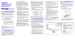
Figure 1. Server Components
A. Front Panel Bezel (removed for clarity)
B. Front Panel LEDs, Switches, and USB Port
C. Four Fan Assemblies
D. SATA hard disk drive bays (2)
E. System Memory
F. Processors and Heat Sinks
G. PCI Support Bracket (Full Length)
H. PCIe Board
I. Hardware RAID Controller board (Not fitted for the SS7G41 Signaling Servers)
J. Power Supply cage
Figure 1. is for reference only. The actual server may vary slightly in terms of boards installed.
35
Chapter 3 Features of the Dialogic® DSI SS7G41 Signaling Server
3.5.3
Front Panel
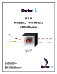
Front Panel with the Bezel Installed
The following figure shows the front panel of the SS7G41 with the bezel installed.
Figure 2. Front Panel (Bezel Installed)
Table 4. Front Panel (Bezel Installed)
Item
Description
A
USB Port
B
Reset Switch
C
Status LEDs
D
ID Switch
E
Power Switch
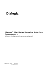
The following figure shows the front panel of the SS7G41 with the bezel removed.
Figure 3. Front Panel (Bezel Removed)
Table 5. Front Panel (Bezel Removed)
Item
3.5.4
Description
A
HDD bay 0 & 1
B
Fans
C
Front Panel; LEDs, Switches, and USB Port
Rear Panel
The following figure shows the rear panel of the SS7G41 Signaling Server.
36
Dialogic® DSI Signaling Servers SS7G41 Hardware Manual Issue 4
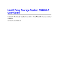
Figure 4. Rear Panel
Table 6. Rear Panel
Item
Description
A
AC (or DC) System Power modules
B
Ethernet ports 0, 1, 2 & 3
C
USB Interfaces
D
VGA video output port (Not used)
E
Serial port
F
PCIe Boards 0 & 1 (SS7 Interface & Digital line Interface boards)
G
Earth Ground
Note: Figure 4. shows a single AC-input power configuration with a filler module
on the right side. Item A can also be configured for Dual AC or Dual DC operation.
37
Chapter 3 Features of the Dialogic® DSI SS7G41 Signaling Server
3.6
Controls and Indicators
3.6.1
Main Switches and LEDs
The front panel of the SS7G41 includes several switches and indicators, which are located on the
front panel.
Figure 5. Switches and LEDs (Front Panel)
Component
Description
USB
Universal serial bus connector (USB 2.0).
RST
Reset button. Push to reboot the server.
Caution: Using this button may result in a service interruption.
38
M Fault
Minor fault indicating a warning. For example, the temperature of a
component has reached a critical temperature reading.
P Fault
Power supply fault. If there is a fault with a fan, temperature, or voltage
over/under reading, the LED illuminates and an audible alarm sounds.
Check the power supply module. Replace the faulty power supply module
with a good module to reset the P Fault LED.
C Fault
Critical fault indicating a non-recoverable event. The system will perform a
graceful shutdown to protect components from thermal damage.
HDD
Hard drive activity. Blinks when drives are being read or written to. It does
contain a fault indicator so it does not change color.
Dialogic® DSI Signaling Servers SS7G41 Hardware Manual Issue 4
3.6.2
Ethernet Port LEDs
Two indicator LEDs are provided for each of the four Ethernet ports. The LEDs are integrated into
the quad RJ45 stacking connector and are designed to support link and activity indications for
each of the four Ethernet ports. The green LED to the left of each connector indicates the status
and activity of the link, and the bi-color LED to the right of each Ethernet connector indicates link
speed. The following table lists the various LED indication combinations and their meanings.
Figure 6. Ethernet Port LEDs
Table 7. Ethernet Port LEDs
Link LED
Indication
Speed LED
Indication
Meaning
Off
Off
Port disconnected. No link
Solid green
Off
Port connected at 10 Mbps, no link activity
Solid green
Solid green
Port connected at 100 Mbps, no link activity
Solid green
Solid amber
Port connected at 1 Gbps, no link activity
Blinking
green
Off
Port connected at 10 Mbps, activity on link
Blinking
green
Solid green
Port connected at 100 Mbps, activity on link
Blinking
green
Solid amber
Port connected at 1 Gbps, activity on link
39
Chapter 3 Features of the Dialogic® DSI SS7G41 Signaling Server
3.7
Signaling Boards
The SS7G41 Signaling Server uses intelligent multi-port interface boards for the processing of
SS7 signaling links. The signaling boards are PCIe form factor boards that can occupy one board
position in a riser board mounted on the server board. SS7 signaling boards each provide four
primary-rate telecommunications (PCM) interfaces, configured at run-time under software control
to operate as a T1 or E1 interface with selectable line code and frame format.
The number of SS7 signaling links that can be terminated by an SS7 signaling board depends on
the board type as described below. Signaling links can operate at 64kb/s, 56kb/s or 48kb/s, and
support Q.703 Annex (HSL).
Depending on the variant, an SS7G41 can contain either one or two Dialogic® DSI SS7MDL4 OR
SS7LDH4 Network Interface Board.
Each SS7MDL4 board supports up to 124 channelized LSL links or four HSL SS7 links.
Each SS7LDH4 board on the SS7G41 supports up to 16 channelized LSL links.
Alternatively, the SS7G41 can be used without SS7 signaling boards, typically for use in SIGTRAN
signaling applications.
For more information about Dialogic SS7 Signaling Boards refer to the following:
http://www.dialogic.com/support/helpweb/signaling
3.8
Power Inputs
The SS7G41 Signaling Server can be ordered with one of the following:
• AC-input power supply
• DC-input power supply
The SS7G41 chassis can contain up to two power supply modules and can be configured as
follows:
• One power supply module installed (this is the factory standard setting). Units configured in
this manner can supply a fully loaded product, but do not provide dual redundancy. The
second position contains a filler module.
• Two power supply modules installed. Units configured in this manner are dual redundant. In
the event of a failure of any one power supply module, the operation of the product is
unaffected. When the product is configured with two power supply modules, the hot-swap
feature allows you to replace a failed module without interrupting system functionality.
Both power supplies provide Earth grounds, but it is advised to use the designated earth ground
connections provided in the back of the server.
40
Dialogic® DSI Signaling Servers SS7G41 Hardware Manual Issue 4
3.8.1
AC Power Input
Note: Ensure that the power source meets the requirements for mains AC power disconnect
and “overcurrent protection” as described in “Warnings, Cautions and Safety
Information: English” on page 7.
The AC power supply module specification is described as follows.
Input
topology
AC input power connectors for each AC-input power
supply module
Connector
type
IEC 320 -C4 Sheet 13.
Input voltage
90VAC to 264VAC.
Frequency
range
Maximum
continuous
input current
47 – 63Hz
8A @ 90 – 132Vac
4A @ 180 – 264Vac
Input Current
The maximum allowable input current shall be 15 Amps
Efficiency
83% minimum at 100-264VAC for the Max load
A single IEC320-C14 receptacle is provided at the rear of each AC-input power module installed in
the system. This connector provides the safety ground connections for the product.
Figure 7. AC Power Input Connector
The use of an appropriately sized power cord and AC main is recommended.
When selecting a suitable AC power outlet for connection of the other end of the power cord,
verify that the outlet is earthed and that it complies with AC power supply warnings in “Warnings,
Cautions and Safety Information: English” on page 7.
If in doubt, consult a qualified service technician.
41
Chapter 3 Features of the Dialogic® DSI SS7G41 Signaling Server
3.8.2
DC Power Input
Important: Ensure that the power source meets the requirements for mains DC power
disconnect and “overcurrent protection” as described in “Warnings, Cautions and Safety
Information: English” on page 7.
The DC power supply module specification is described as follows.
Input topology
Four-terminal DC input power connector for each
power supply module
Connector type
Screw barrier connectors
Input voltage
- 36 to -72 VDC (nominal -48 to -60 VDC)
Input DC voltage can be taken to 75V For One Second.
Maximum input
current
Input power
Efficiency
16.0 Amps
Note: Maximum input current is measured at the lowest
input voltage that the power supply continues to operate.
This is not the same as used for determining agency input
current markings.
576 Watts, fully equipped
>84% minimum at -48 to -72V for the max load
A 3-pin DC connector (Positronic Industries p/n PLAH03M4BN0A1-AA- E1A or equivalent) is used
in the DC power supply modules to provide the DC-input power connection.
A 4m DC cable is provided with all DC products, rated at 25Amps. Using appropriately sized power
wire and DC main is recommended.
42
Dialogic® DSI Signaling Servers SS7G41 Hardware Manual Issue 4
Figure 8. DC Power Input Connector
The pin-out of the DC input connector is shown in the table below.
Table 8. DC Power Supply Module Input Pin Assignments
Pin#
Description
1
RTN (EGND)
2
-48V
3
GND
43
Chapter 3 Features of the Dialogic® DSI SS7G41 Signaling Server
3.9
PCM Interface Ports
The PCM interface specification is described as follows.
Ports
4 T1/E1 signaling ports
Data rate
2048 kbit/s (E1) or 1544 kbit/s (T1) user configurable for each
individual port
Connector
type
RJ45
Pulse shape
ITU-T G.703, AT&T TR62411 or TIA-968-A/CS-03
Frame
format
E1, E1-CRC4, D4, ESF, ESF-CRC6
Line code
HDB3, AMI (ZCS), AMI, B8ZS
Each SS7 Signaling Board provides four primary rate telecommunications (PCM) interfaces,
configured at run-time under software control to operate as balanced T1 or E1 ports, with
selectable line code and frame format. For information on setting the port configurations, see the
appropriate User Manual. “Related Information” on page 27 lists these manuals.
Figure 9. E1/T1 Ports on Dialogic® DSI SS7LDH4 Network Interface Boards
Figure 10. E1/T1 Ports on Dialogic® DSI SS7MDL4 Network Interface Boards
The T1/E1 ports on the SS7 Signaling Boards are Safety Extra Low Voltage (SELV), that is, the
apparatus connects to the outside network via Network Termination units (NT1). Use twisted-pair,
screened cables, grounded at both ends. Also refer to the “Telecommunications” section in the
Dialogic® DSI SS7G41 Signaling Servers Regulatory Notices for information on potential usage as
TNV-1 ports.
The connectors are 8-way RJ45, and are labeled L1 to L4 in Figure 9 and Figure 10. These labels
can be used together with the SS7 Signaling Board position number to give each port a unique
identifier for wiring schedules and unit configuration.
44
Dialogic® DSI Signaling Servers SS7G41 Hardware Manual Issue 4
The connector pinout and signal descriptions are shown in below.
Table 9. PCM Interface Port Connector Pinouts
Pin No
Direction
Function
1
Input
Receive
2
Input
Receive
3
Not applicable
Not Used
4
Output
Transmit
5
Output
Transmit
6
Not applicable
Not Used
7
Not applicable
Not Used
8
Not applicable
Not Used
3.10
Signaling Links
The signaling link specification is described as follows.
Signaling
links
The number of signaling links depends on the product variant, which
determines the type and number of SS7 Signaling Boards included.
Source
PCM (T1/E1) interface
Data rate
48 kbit/s, 56 kbit/s and 64 kbit/s LSL and HSL (Q.703 Annex A). HSL
only available on SS7G41xMxxx product variants.
Timeslot
Fully programmable
45
Chapter 3 Features of the Dialogic® DSI SS7G41 Signaling Server
3.11
Ethernet Interfaces
The Ethernet interfaces are described as follows.
Quantity
Four provided by the server board
Connector
RJ45
Speed
10Base-T (10 Mbit/s), 100BaseTX (100 Mbit/s) and 1000Base-T
(1 Gigabit/s), automatically detected and switched.
For EMC product regulation compliance for intra-building lightning surges, the product must only
be used with LAN cables that are grounded at both ends.
Four Ethernet connectors are provided on the SS7G41 Server Board. Figure 11 shows the
Ethernet connectors provided by the Server Board.
Additional Ethernet ports may be added by fitting a PCIe SS7G41NIC’s, giving a total of six ports.
When fitting a single additional SS7G41NIC accessory board it must be fitted in the top slot (slot
1). This will provide Eth4 and Eth5 (reading left to right)
The Ethernet interface connectors incorporate status LED indicators. The LEDs on the network
interface connectors indicate link/activity on the network and the speed of operation. The green
LED, when on, indicates network connection and when blinking indicates TX/RX activity. The
speed LED indicates 1000 Mbps when amber, 100 Mbps when green, and 10 Mbps when off.
Figure 10 shows the Ethernet connector pinouts.
A NIC Activity LED (green) on the front panel provides an indication of activity on the ENET 1 or
ENET 2 ports. See Section 3.6.1, “Main Switches and LEDs” on page 38 for more information.
Figure 11. Ethernet Interface Connectors
For information about the operation of the LEDs on the Ethernet Interface Connectors, see
Section 3.6.2, “Ethernet Port LEDs” on page 39.
46
Dialogic® DSI Signaling Servers SS7G41 Hardware Manual Issue 4
Table 10. Ethernet Connector Pin-Out
Pin
Number
Signal
Name
Description
1
BI_DA+
Bi-directional pair A, +
2
BI_DA-
Bi-directional pair A, -
3
BI_DB+
Bi-directional pair B, +
4
BI_DC+
Bi-directional pair C, +
5
BI_DC-
Bi-directional pair C, -
6
BI_DB-
Bi-directional pair B, -
7
BI_DD+
Bi-directional pair D, +
8
BI_DD-
Bi-directional pair D, -
3.12
Serial Port (COM1)
The serial interface port specification is described as follows.
Quantity
One mounted on the rear of the chassis.
Note: The serial port located on the front of the chassis is
not enabled on these products.
Connector
DB9
Electrical
RS232: 9600, n, 8, 1, no flow control
Signal
TXD, RXD, DSR, DTR, GND
The serial port (COM1) provided on the back panel is an RS232 port using a DB9 connector
(Figure 12). The serial port can be used for configuration and management of the product. The
serial port is designated as SELV.
47
Chapter 3 Features of the Dialogic® DSI SS7G41 Signaling Server
Figure 12. Serial Port (COM1) Connector
Table 11. Rear Panel Serial Port (DB9) Connector Pin-Out
48
Pin
Number
Signal
1
N/A
2
RXD - Received data
3
TXD - Transmit Data
4
DTR - Data terminal ready
5
GND - Signal ground
6
DSR – Data set ready
7
N/A
8
N/A
9
N/A
Dialogic® DSI Signaling Servers SS7G41 Hardware Manual Issue 4
3.13
Universal Serial Bus (USB) Interface
The USB port specifications are as follows.
Quantity
Three external USB ports.
Note: There is an additional USB port, Port 3, located internally that
is not used at this time.
Location
USB ports 0 and 1 are located on the rear panel.
USB port 2 is located on the front panel.
Figure 13. Rear Panel Showing USB Ports
Figure 14. Front Panel Showing USB Port
The SS7G41 supports connection of a single USB disk device to a USB port for maintenance
purposes.
49
Chapter 3 Features of the Dialogic® DSI SS7G41 Signaling Server
Note: Connection of multiple USB devices is not supported.
Figure 15. External USB Connector
Table 12. USB Connector Pin-Out
Pin
Number
Signal
1
Fused Vcc (+ 5V w/over-current monitor of ports 0, 1, 2 and 3)
2
DATAL0 (differential data line paired with DATAH0)
3
DATAHO (differential data line paired with DATAL0)
4
GND
Note: An optional second power supply module can be fitted on the SS7G41.
50
Dialogic® DSI Signaling Servers SS7G41 Hardware Manual Issue 4
4 Working with the Dialogic® DSI SS7G41 Signaling
Server
IMPORTANT
The actions described in this chapter must be performed by a qualified service technician
4.1
Overview
This chapter contains the following topics:
•
•
•
•
•
•
•
•
•
“Guidelines for Installation” on page 51
“Removing and Installing the Front Bezel” on page 52
“Removing and Installing the Chassis Cover” on page 53
“Removing the Processor Air Duct” on page 56
“Replacing a Power Supply” on page 59
“Grounding a DC-Powered System” on page 58
“Installing the New Hard Disk Drive” on page 62
“Preparing Dialogic® DSI SS7 Network Interface Boards for Installation” on page 63
“Back-up Battery - Replacement” on page 72
For an overview of the internal product layout, see “Main Features” on page 34.
Before starting these procedures, read the warnings and cautions in Chapter 1, “Warnings,
Cautions and Safety Information”.
4.2
Guidelines for Installation
Installation of a Dialogic® DSI SS7G41 Signaling Server involves the following tasks performed in
the order shown. References to more detailed task descriptions are provided where appropriate.
Follow the steps below to install an SS7G41 unit:
1. Read the warnings and cautions listed in Chapter 1, “Warnings, Cautions and Safety
Information”.
2. Install any hardware options purchased. (For example, if you are adding an extra power
supply, see Section 4.8, “Replacing a Power Supply” on page 59).
3. Physically install the product in an equipment rack or as a free standing unit.
4. Connect the product to ground. If you are installing:
— A DC-powered product, see Section 4.7, “Grounding a DC-Powered System” on page 58.
— An AC-powered product, the ground connection and power connection are part of the same
operation. See the step below.
5. Connect the power source. If you are:
— Installing a DC-powered product for the first time, see Section 3.8.2, “DC Power Input” on
page 42 and Section 4.8.2, “Installing the Power Supply” on page 61.
51
Chapter 4 Working with the Dialogic® DSI SS7G41 Signaling Server
— Replacing a DC-powered product, see Section 4.8, “Replacing a Power Supply” on page 59.
— Installing an AC-powered product, see Section 3.8.1, “AC Power Input” on page 41 and
Section 4.8.2, “Installing the Power Supply” on page 61.
6. Connect line interface and Ethernet interface cables. See Section 3.9, “PCM Interface Ports” on
page 44 and Section 3.10, “Signaling Links” on page 45 for connector details and pinout
information for the various interfaces. To avoid EMC problems with the installation, comply
with the instructions and advice given in the “Essential Compliance Information” section in the
Dialogic® DSI SS7G41 Regulatory Notices (provided with the product).
For safety and operational aspects affecting network connections, comply with the advice
given in the Dialogic® DSI SS7G41 Regulatory Notices. In particular, “Essential Compliance
Information: Telecommunications” for general requirements, and region-specific information
in “Regional Regulatory Notices”, specifically:
— For the United States, “FCC Part 68 Statement”.
— For Canada, “Telecommunications Attachment Notice”.
— For Australia and New Zealand, “Telecommunications Notice”.
7. Power up the product.
8. Complete the following software and configuration steps, all of which are fully described in the
appropriate User Manual.
— Check whether a software download and upgrade is required.
— Install optional software licenses.
— Set the IP addresses of the unit.
— Enable the selected operating mode (SIU or SWS).
Note: You must ensure that the product configuration, and any related application that is
running, provides an implementation that complies with the services offered by the
local Public Switched Telephone Network (PSTN) operator. If in doubt, consult the
network specifications.
4.3
Removing and Installing the Front Bezel
4.3.1
Removing the Front Bezel
During this procedure, ensure that you hold the bezel in place to prevent it from falling from the
chassis.
1. Unscrew both the left and right-side captive screws to release the bezel (“A” in Figure 16
below).
2. Remove the front bezel from the chassis.
52
Dialogic® DSI Signaling Servers SS7G41 Hardware Manual Issue 4
Figure 16. Removing the Front Bezel
4.3.2
Re-Installing the Front Bezel
While holding the front bezel in place, insert and then tighten the left and right captive screws at
the edges of the bezel.
4.4
Removing and Installing the Chassis Cover
You will need to remove the top cover to add or replace components inside the server.
4.4.1
Removing the Chassis Cover
Attach an anti-static strap
Before removing the chassis cover, attach an anti-static strap as follows:
1. Attach a user-supplied anti-static wrist strap to the server before handling any internal or
removable components.
2. Use best current practices and follow all manufacturers’ recommendations when dealing with
ESD and SS7G41 chassis.
Chassis Cover
1. Remove and save the eight screws near the top-front and middle of the chassis cover (“B” in
Figure 17 below).
53
Chapter 4 Working with the Dialogic® DSI SS7G41 Signaling Server
Figure 17. Removal of top cover
2. Slide the top cover back approximately ¾” until it stops. (“C”).
Figure 18. Slide Cover to Remove/Install
3. Lift the cover straight up to remove it. (“C”).
4.4.2
Installing the Chassis Cover
Before You Begin
1. Prior to installing the chassis top cover, check for components that may cause interference.
The cover should not be pressing against any of the components within the chassis.
2. Align the chassis cover over the chassis leaving approximately 3/4” horizontal gap between
the front edge of the cover and the front edge of the chassis, and then lower the cover onto
54
Dialogic® DSI Signaling Servers SS7G41 Hardware Manual Issue 4
the chassis (the gap is required so that the cover drops down and engages with slots in the
chassis). See Figure 19.
3. Slide the cover towards the front of the chassis until it stops.
Caution:After the cover stops, make sure that the clearance holes in the cover align with the
threaded holes in the chassis, otherwise the cover retention screws may not go in
properly and may strip the threaded holes in the chassis.
4. Install the eight cover retention screws as shown in the figure below:
Figure 19. Chassis Cover Retention Screws
Caution:Do not over tighten the cover retention screws. Doing so may strip the threaded holes
in the chassis. The torque specification for the screws is 3.5 kgf-cm (3.04 lbf-inches).
55
Chapter 4 Working with the Dialogic® DSI SS7G41 Signaling Server
4.5
Removing the Processor Air Duct
This procedure is required only to access Processor, DIMM sockets, to set the SW1 DIP switches,
riser, and to access the disk drive cable assembly.
1. Ensure that you have followed the safety instructions set out in Essential Safety: Before You
Begin.
2. Remove the top cover. For instructions, see Section 3.5.2, “Server Components” on page 35.
3. Identify and remove the Air Duct assembly. Take note of the position of the air duct for
reassembly later. Lift the air duct assembly vertically from the server platform (“A” in
Figure 20 below). There is no physical retention hardware, only a friction fit holding the air
duct in place.
Figure 20. Air Duct Location
56
Dialogic® DSI Signaling Servers SS7G41 Hardware Manual Issue 4
4.6
Re-installing the Processor Air Duct
Replace the air duct assembly as follows:
1. Position the processor air duct assembly over the processor sockets and DIMM sockets as
shown in Figure 20.
2. Lower the air duct into position.
— The ATX power bundle may need to be temporarily pulled up and away from the heat sink
to allow the air duct to be installed.
— The internal air baffle that is part of the air duct assembly must be positioned on the
outside of the memory (DIMMs). This may require manually adjusting the internal baffle so
that it doesn’t catch on the DIMM socket clips. See Figure 21.
— Use caution and make sure that there are no wires pinched as a result of the air duct being
installed. There are a number of places around the perimeter of the air duct where this can
happen. See Figure 21.
— The air duct is retained in the chassis by friction; there is no hardware holding it in place.
3. When properly installed, the top of the installed air duct should be flush with the top surface of
the fan housing (see Figure 20).
Figure 21. Air Duct Installation
57
Chapter 4 Working with the Dialogic® DSI SS7G41 Signaling Server
4.7
Grounding a DC-Powered System
Grounding the server is required because DS-1 connections can be susceptible to lightning strike
or power cross before a power source is provided for the device. Do not connect the server to a
power source until it is properly grounded.
Follow the steps below:
1. Use a two-hole #10x5/8 ground lug (included in the kit) or equivalent to ground the server.
2. Crimp the grounding wire to the lug (refer to “Grounding the Server” on page 9).
3. Remove the screws that come with the server and use them to secure the lug as shown in the
figure below.
Note: Refer to Figure 23 for the location of earth ground.
Figure 22. Grounding the server
4. Tighten each screw to 10 llbs-in torque.
Figure 23. Earth Ground, Rear Panel
58
Dialogic® DSI Signaling Servers SS7G41 Hardware Manual Issue 4
4.8
Replacing a Power Supply
The power source should be disconnected from any module while it is being removed or installed.
When hot-swap functionality is required, verify that one module remains installed, connected, and
powered at all times.
The figure below shows the AC and DC Power Supplies from the Rear Panel.
Figure 24. AC and DC Power Supplies, Rear Panel
Table 13. AC and DC Power Supplies, Rear Panel
Item
Description
A
Handle to remove power supply
B
AC power IN
C
Power supply status LED
D
DC power IN
E
Ground studs (used with DC input power supply)
F
Safety Lock
Note: Ensure that the power source meets the requirements for mains DC power disconnect
and overcurrent protection.
For information about power inputs, see “Section 3.8, “Power Inputs” on page 40.
Caution:Both module positions should have either a power supply module or a filler module
installed whenever the product is operational. Otherwise the cooling efficiency of the
remaining module is impaired. During a hot-swap operation there is a brief interval
59
Chapter 4 Working with the Dialogic® DSI SS7G41 Signaling Server
when one position is empty. If the replacement power supply module is not
immediately available, then a filler module must be installed.
Caution:If you are replacing an AC power supply, note that AC powered units are grounded via
the AC power supply cord(s). If all power cords or power modules are to be removed,
you must first disconnect any TNV interface cables from the unit.
Caution:If only one module is installed, it must be in the left-side slot and a power supply filer
panel must be installed in the right slot for proper system cooling.
4.8.1
Removing the Power Supply
Caution:If you are removing an AC power supply, note that AC powered units are grounded via
the AC power supply cord(s). If all power cords or power modules are to be removed,
you must first disconnect any TNV interface cables from the unit.
Procedure
1. If you are removing:
— An AC power supply and you have either one AC power supply module, or you have two
power supply modules but one of them does not have a power lead connected, remove any
TNV interface cables from the unit.
— A DC power supply, continue with Step 2.
2. If you do not have a second, redundant power supply, power down the server system and
unplug all peripheral devices.
3. Disconnect the appropriate power cable.
4. Press and hold the safety lock to the right to disengage the power supply.
Figure 25. Releasing Power Supply
5. Grasp the handle and pull the power supply from the chassis.
60
Dialogic® DSI Signaling Servers SS7G41 Hardware Manual Issue 4
Figure 26. Removing Power Supply
4.8.2
Installing the Power Supply
Caution:If you are installing an AC power supply, note that AC powered units are grounded via
the AC power supply cord(s). If all power cords or power modules are to be removed,
you must first disconnect any TNV interface cables from the unit.
Procedure
1. If you are installing:
— An AC power supply and you have either one AC power supply module, or you have two
power supply modules but one of them does not have a power lead connected, remove any
TNV interface cables from the unit.
— A DC power supply, continue with Step 2.
2. Make sure the safety lock is pressed toward the left while sliding the module into the power
supply cage.
Note: Verify that the power source meets the requirements for mains DC power disconnect
and overcurrent protection.
61
Chapter 4 Working with the Dialogic® DSI SS7G41 Signaling Server
4.9
Removing and Installing a Hard Disk Drive (HDD)
4.9.1
Removing the Hard Disk Drive
1. Remove the Front Bezel following - refer to Section 4.3.1, “Removing the Front Bezel” on
page 52.
2. Undo the carrier retaining screw and pull the retractor handle to remove the HDD carrier from
the chassis.
3. Place the carrier on a grounded ESD mat.
4. Unscrew the four Phillips head screws from the carrier.
5. Remove the hard drive from the carrier.
Figure 27. Removing the Hard Disk Drive
4.9.2
Installing the New Hard Disk Drive
1. Place the equipment on a grounded ESD mat.
2. Align the four screw holes of the hard drive into the carrier from below. The electrical
connector of the hard drive must extend beyond the edge of the carrier.
3. Replace the four Phillips-head screws securely into the hard drive. The figure below shows the
location of the screws and electrical connector.
Figure 28. Installing a New Hard Disk Drive
4. Insert the new hard disk drive as shown below. Carefully align the hard drive guides.
5. Close the extractor handle and tighten the retaining screw.
62
Dialogic® DSI Signaling Servers SS7G41 Hardware Manual Issue 4
6. Replace the Front Bezel - refer to Section 4.3.2, “Re-Installing the Front Bezel” on page 53.
Figure 29. Inserting Hard Disk Drive
4.10
Preparing Dialogic® DSI SS7 Network Interface Boards
for Installation
The SS7G41is available with either zero or one signaling boards installed. The types of signaling
boards that are installed depends on the model number.
The procedures in Section 4.10.1 to Section 4.10.2 describe how to prepare to install new boards.
The general description can also be applied to the replacement of a failed board.
4.10.1
Preparing Dialogic® DSI SS7LDH4 Network Interface Boards for
Installation
Use Table 14 to determine the position and configuration of Dialogic® DSI SS7LDH4 Network
Interface Boards, and to prepare the boards for installation.
63
Chapter 4 Working with the Dialogic® DSI SS7G41 Signaling Server
Table 14. SS7LDH4 Network Interface Board Positions and Configurations
Board
Position
SW1 ADDR
Setting
0
0
1
1
Figure 30. Dialogic® DSI SS7LDH4 Network Interface Board Layout
Procedure
Prepare an SS7LDH4 Network Interface Board for installation as follows:
64
Dialogic® DSI Signaling Servers SS7G41 Hardware Manual Issue 4
4.10.2
Preparing Dialogic® DSI SS7MDL4 Network Interface Boards for
Installation
Figure 31. Dialogic® DSI SS7MDL4 Network Interface Board Layout
Procedure
Prepare an SS7MDL4 Network Interface Board for installation as follows:
1. Unscrew and replace the Low Profile mounting bracket with the Full Height Bracket (included
in the board kit).
65
Chapter 4 Working with the Dialogic® DSI SS7G41 Signaling Server
4.10.3
Installing or Replacing a Dialogic® DSI SS7 Network Interface Board
Essential Safety: Before You Begin
1. Read the warnings and cautions in Chapter 1.
2. Turn off all peripheral devices connected to the server.
3. Turn off the server.
4. Label and disconnect all peripheral cables and all telecommunication lines connected to
connectors or ports on the back of the product. Follow the instructions in Section 4.11,
“Replacing a PCIe Board” on page 66 to add or remove the DSI SS7 Network Interface board.
5. Disconnect the power cord.
Procedure
Install/replace an SS7 Network Interface Board as follows:
1. Verify that, in each case, the SS7 Network Interface Board to be fitted is correctly configured
and prepared.
2. Ensure that you have followed the safety instructions set out in Essential Safety: Before You
Begin, above.
3. Remove the top cover. See Section 3.5.2, “Server Components” on page 35.
4.11
Replacing a PCIe Board
This section describes how to replace a PCIe Board including the following:
•
•
•
•
Removing PCI Support Brackets and PCI Filler Plates
Install PCIe Board(s) into Chassis
Reinstall and Adjust the PCI Support Bracket
Install the Chassis Top Cover
4.11.1
Removing PCI Support Brackets and PCI Filler Plates
1. Locate the two screws on the outside rear of the chassis (“A” in the figure below) that secure
the PCI faceplates to the chassis. Unscrew both of them.
Figure 32. PCI Faceplate Retention Screw Locations
2. Unscrew the PCI Support Bracket Screw and save it.
66
Dialogic® DSI Signaling Servers SS7G41 Hardware Manual Issue 4
Figure 33. PCI Support Bracket
3. Slide the bracket towards the front of the chassis until it stops, approximately ½”.
4. Lift the bracket up and out of the chassis.
Figure 34. PCI Support Bracket
5. Remove any PCI filler plates or PCIe boards as required.
4.11.2
Installing the PCIe Board(s) into the Chassis
1. PCIe boards are to be installed into the chassis area “A” as shown in the figure below. When
fitting a single Dialogic® DSI SS7 Network Interface Board it must be fitted in the bottom slot
(slot 0). When fitting a single SS7G41NIC it must be fitted in the top slot (slot 1).
Figure 35. PCIe Board Installation Area
2. Lower the first board into the chassis, slipping one end of its faceplate into the opening at the
chassis back panel sheet metal (“A” in the figure below).
67
Chapter 4 Working with the Dialogic® DSI SS7G41 Signaling Server
Figure 36. Inserting the PCIe Board Faceplate into the Chassis Slot
3. Align the board’s PCIe connector notch (“B” in Figure 38) with the mating connector key on
the chassis PCI riser assembly (“A” in the figure below) then press the PCIe board fully into
the PCI riser connector. When properly installed, the mating of the board and riser connectors
should look like that shown in Figure 39.
68
Dialogic® DSI Signaling Servers SS7G41 Hardware Manual Issue 4
Caution:Press the PCIe board straight into the PCI riser connector. Tipping the board while
installing may cause damage to the PCIe board or riser assembly.
Figure 37. PCI Riser Connectors and Keying Features
Figure 38. PCIe Board Positioned for Install
Figure 39. PCIe Board Properly Installed into PCI Riser Connector
Caution:Make sure that the PCIe Board is fully seated in the riser connector and that the board’s
faceplate (“B” in Figure 41) is contacting the chassis rear panel (“A”) with no gap. If
there is a gap between the faceplate and the rear panel, then the board may not be
fully seated in the PCI riser connector or the board is not perpendicular to the riser
69
Chapter 4 Working with the Dialogic® DSI SS7G41 Signaling Server
assembly. An improperly seated PCIe board may prevent the board from functioning
and may cause problems when installing the PCI Support Bracket.
Figure 40. PCIe Board Faceplate Contacting Chassis
4.11.3
Reinstalling and Adjusting the PCI Support Bracket
The PCI Support Bracket (removed in an earlier step) secures up to two PCIe Boards in the chassis. There are two adjustable card guides that are part of the PCI Support Bracket assembly. Both
card guides should be adjusted to the same dimensions. To adjust the card guides, follow the
steps below.
1. Loosen the two knurled thumbscrews (“A” in the figure below) just enough so that the card
guide (“B”) can slide along the length of the PCI Support Bracket.
Figure 41. PCI Card Guides and Adjustment Screws
2. Move the card guides all the way to their maximum open position (Figure 41 shows the guides
in their maximum open position).
3. Lower the PCI Support Bracket into the chassis keeping the bracket in the most-forward
position possible (that is, towards the front of the chassis) and against the side of the chassis
so that the card guides clear the PCIe board(s) as the bracket is being lowered.
Note: It may be necessary to push any disk drive cables that interfere with the PCI Support
Bracket temporarily out of the way.
4. Continue lowering the bracket until it bottoms against the chassis.
5. With the bracket fully lowered into the chassis, slowly slide the bracket towards the rear of the
chassis until it stops. The screw holes in the PCI Support Bracket and the chassis should line
up as shown below.
70
Dialogic® DSI Signaling Servers SS7G41 Hardware Manual Issue 4
Figure 42. PCI Support Bracket and Chassis Hole Alignment (bracket lifted for clarity)
6. Reinstall the PCI Support Bracket screw that was removed earlier
7. With one hand, slide the card guides towards the back of the chassis and the PCIe boards, and
with the other hand move the PCIe boards slightly up or down so that the card guides
completely capture and support the PCIe Boards.
Caution:It is important to make sure that each of the two card guides (“B” in the figure below)
completely engage and secure the boards (“A”).
Figure 43. PCIe Board Engaged with Card Guide
8. While still applying pressure on the card guide against the PCIe Board, tighten the knurled
thumbscrew on one card guide, then repeat for the other card guide. (“A” in Figure 41).
9. From the outside rear of the chassis, secure the newly installed PCI card faceplate to the
chassis using the screw saved in an earlier step
10.Refit the chassis cover - refer to “Installing the Chassis Cover” on page 54.
Caution:The knurled thumbscrews should be tightened using a Phillips screwdriver, and
tightened securely enough so that there is no possibility of loosening during shipping
and handling.
Note: Even if only one PCIe Board is to be installed in the chassis, both card guides should be
adjusted as if both Boards were installed.
71
Chapter 4 Working with the Dialogic® DSI SS7G41 Signaling Server
4.12
Back-up Battery - Replacement
A lithium battery on the server board provides power to maintain date and time settings in the
real time clock (RTC) for up to ten years in the absence of main AC or DC power. When the battery
starts to weaken, it loses voltage, and the date and time settings may be lost or corrupted.
The battery can be replaced by one labeled with manufacturer and part number information that
is identical to that marked on the original battery. Alternatively, contact your customer service
representative for advice on approved equivalent devices.
Essential Safety: Before You Begin
1. Read the warnings and cautions in Chapter 1.
2. Turn off all peripheral devices connected to the server.
3. Turn off the server.
4. Disconnect the power cord.
5. Label and disconnect all peripheral cables and all telecommunication lines connected to
connectors or ports on the back of the product.
WARNING
Danger of explosion if battery is replaced incorrectly. Replace only with the
same or equivalent type recommended by the equipment manufacturer.
Discard used batteries according to the manufacturer's instructions.
ADVARSEL!
Lithiumbatteri - Eksplosionsfare ved fejlagtig håndtering. Udskiftning må kun
ske med batteri af samme fabrikat og type. Levér det brugte batteri tilbage
til leverandøren.
ADVARSEL
Lithiumbatteri - Eksplosjonsfare. Ved utskifting benyttes kun batteri som
anbefalt av apparatfabrikanten. Brukt batteri returneres
apparatleverandøren.
VARNING
Explosionsfara vid felaktigt batteribyte. Använd samma batterityp eller en
ekvivalent typ som rekommenderas av apparattillverkaren. Kassera använt
batteri enligt fabrikantens instruktion.
VAROITUS
Paristo voi räjähtää, jos se on virheellisesti asennettu. Vaihda paristo
ainoastaan laitevalmistajan suosittelemaan tyyppiin. Hävitä käytetty paristo
valmistajan ohjeiden mukaisesti.
72
Dialogic® DSI Signaling Servers SS7G41 Hardware Manual Issue 4
4.12.1
Replacing the Back-up Battery
To replace the back-up battery, follow this procedure:
1. Observe the information and warnings detailed in Essential Safety: Before You Begin, above,
and in Chapter 1.
2. Power down the server system and unplug all peripheral devices and the power cords.
3. Remove the top cover. For instructions, see “Removing the Chassis Cover” on page 53.
4. Locate the battery on the server board. See Figure 44 below.
5. Gently press the battery retainer tab clear of the battery.
Caution:Do not bend the tab further then needed to clear the battery)
6. Remove the battery from its socket.
Figure 44. Replacing the Back-up Battery
7. Dispose of the old battery according to local ordinance.
8. Remove the new battery from its package.
9. Being careful to observe the correct polarity, gently push the retainer tab away and insert the
battery into the battery socket.
10.Replace the top cover. See “Removing the Chassis Cover” on page 53.
11.Follow the steps below depending if the unit is AC or DC power:
— AC units, reconnect the power cord(s)
— DC units, reconnect the ground to the server.
12.Reconnect all peripheral devices.
13.Re-set the RTC via the CNTDS command. For more information about the CNTDS command,
refer to the appropriate <Operating Mode> User Manual. See “Related Information” on
page 27 which lists the various user manuals.
73