1
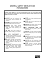
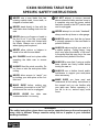
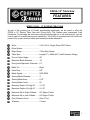
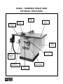
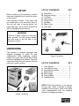
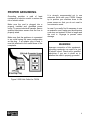
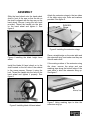
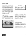
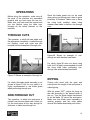
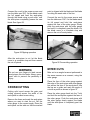
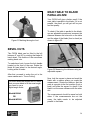
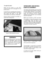
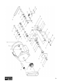
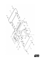
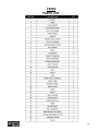
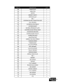
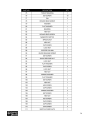
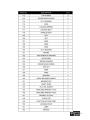
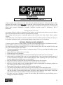
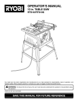
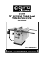
CX204 10” SCORING TABLE SAW WITH RIVING KNIFE User Manual (Fence Sold Separately) TABLE OF CONTENTS General Safety Instructions for Machines ............................................................... 3 Specific Safety Instructions..................................................................................... 4 CX204 Features...................................................................................................... 5 Physical Features ................................................................................................... 6 Set Up..................................................................................................................... 7 Un-Packing & Inventory .......................................................................................... 7 Proper Grounding ................................................................................................... 8 Assembly ................................................................................................................ 9 Installing Saw Blade................................................................................................ 11 Installing the Scoring Blade .................................................................................... 11 Installing the Fence Scale....................................................................................... 12 Blade Guard Spreader ............................................................................................ 12 Table Insert ............................................................................................................. 13 Installing the Blade Guard....................................................................................... 13 Basic Controls.........................................................................................................14 Test Run ................................................................................................................. 14 Connecting to a Dust Collector ............................................................................... 15 Blade Guard............................................................................................................ 15 Riving Knife............................................................................................................. 16 Scoring Saw Blade.................................................................................................. 16 Adjusting the Scoring Blade.................................................................................... 16 Work-Piece Inspection ............................................................................................ 17 Operations .............................................................................................................. 18 Through Cuts .......................................................................................................... 18 Non-Through Cuts .................................................................................................. 18 Ripping.................................................................................................................... 18 Crosscutting ............................................................................................................ 19 Miter Cuts ............................................................................................................... 19 Bevel Cuts .............................................................................................................. 20 Main Table to Blade Parallelism.............................................................................. 20 Spreader & Riving Knife Alignment......................................................................... 21 Replacing the V-Belts ............................................................................................. 22 Miter Gauge Adjustment ......................................................................................... 22 Maintenance ........................................................................................................... 23 Parts Breakdown & List.......................................................................................24-31 Warranty ................................................................................................................. 32 2 GENERAL SAFETY INSTRUCTIONS FOR MACHINES Extreme caution should be used when operating all power tools. Know your power tool, be familiar with its operation, read through the owner’s manual and practice safe usage procedures at all times. ALWAYS read and understand the user manual before operating the machine. CONNECT your machine ONLY to the matched and specific power source. ALWAYS wear safety glasses respirators, hearing protection and safety shoes, when operating your machine. DO NOT wear loose clothing or jewelry when operating your machine. A SAFE ENVIRONMENT is important. Keep the area free of dust, dirt and other debris in the immediate vicinity of your machine. BE ALERT! DO NOT use prescription or other drugs that may affect your ability or judgment to safely use your machine. DISCONNECT the power source when changing drill bits, hollow chisels, router bits, shaper heads, blades, knives or making other adjustments or repairs. NEVER leave a tool unattended while it is in operation. NEVER reach over the table when the tool is in operation. ALWAYS keep blades, knives and bits sharpened and properly aligned. ALL OPERATIONS MUST BE performed with the guards in place to ensure safety. ALWAYS use push sticks and feather boards to safely feed your work through the machine. ALWAYS make sure that any tools used for adjustments are removed before operating the machine. ALWAYS keep the bystanders safely away while the machine is in operation. NEVER attempt to remove jammed cutoff pieces until the saw blade has come to a full stop. 3 CX204 SCORING TABLE SAW SPECIFIC SAFETY INSTRUCTIONS NEVER use a saw blade that has missing carbide teeth, loose teeth, or chipped or broken teeth. NEVER stand directly in line with the saw blade when feeding stock into the saw. NEVER place your fingers or hands in the line of cut. If you slip, your hands or fingers may come into contact with the blade. Always use a push stick when ripping narrow pieces. NEVER allow visitors or helpers to stand in line with the saw blade. ALL GUARDS must be in place while operating the table saw to ensure safety. ALWAYS feed the stock smoothly. Do not force or twist the work-piece while cutting. NEVER allow anyone to “assist” you by holding your work-piece at the outfeed end. MAKE SURE before making any adjustments, the switch is in the “OFF” position and the cord is un-plugged. NEVER LEAVE the table unattended while it is running. DO NOT attempt to remove jammed pieces unless the table saw has come to a complete stop and the power switch has been turned to the OFF position and cord is unplugged. NEVER attempt to cut stock “freehand”, always use the rip fence or miter gauge. ALWAYS make sure that the rip fence is properly squared to the saw blade to prevent kickback. ALWAYS make sure that your saw is in a stable position. Cutting heavy, long stock may alter the stability of the saw. In the event that this may occur, the saw should be firmly bolted to the floor. ALWAYS be sure that if using a mobile base, wheels are firmly locked before turning the saw on. ALWAYS use a feather board and/or hold-downs to support your work-piece when necessary. MAKE SURE you have read and understood all the safety instructions in the manual and you are familiar with your table saw, before operating it. If you fail to do so, serious injury could occur. saw WARNING The safety instructions given above can not be complete because the environment in every shop is different. Always consider safety first as it applies to your individual working conditions. 4 CX204–10” Table Saw FEATURES MODEL CX204 – 10” SCORING TABLE SAW As part of the growing line of Craftex woodworking equipment, we are proud to offer the CX204 a 10” Scoring Table Saw with Riving Knife. The Craftex name guarantees Craft Excellence. By following the instructions and procedures laid out in this user manual, you will receive years of excellent service and satisfaction. The CX204 is a professional tool and like all power tools, proper care and safety procedures should be adhered to. Motor .............................................. 3-HP, 220-V, Single Phase TEFC Motor Drive System .................................. Miter Gauge.................................... T-Slot Miter Gauge Table Size....................................... Length 27” x Width 44.5” (with Extension Wings) Floor to Table Height ...................... 36” Maximum Blade Diameter .............. 10” Riving Knife/Spreader Thickness.... 0.1” Blade Tilt......................................... Right Arbor Size....................................... 5/8” Blade Speed ................................... 5200 RPM Scoring Blade Diameter.................. 3” Scoring Blade Bore......................... 0.78” Scoring Blade Teeth ....................... 20 Maximum Depth of Cut @ 90° ........ 3-1/16” Maximum Depth of Cut @ 45° ........ 2-1/16” Maximum Rip to Right of Blade ...... 20” Edge of Table Maximum Rip to Left of Blade......... 24” Edge of Table Dust Collection Ports ...................... One 4” Port Warranty ......................................... 3 Years 5 CX204 – SCORING TABLE SAW PHYSICAL FEATURES Blade Guard Extension Wing Extension Wing Miter Gauge Motor Cover Blade Tilt Lock ON / OFF Magnetic Switch Blade Height Hand Wheel Blade Tilt Hand Wheel Table Tilt Scale 6 SETUP Before setting up your machine you should read and understand the instructions given in this manual. The unpainted surfaces of this table saw are coated with a rust preventive waxy oil that you will want to remove before you begin assembly. Use a solvent cleaner that will not damage painted surfaces. LIST OF CONTENTS A. B. C. D. E. F. G. H. QTY Table Saw........................................ Extension Wings .............................. 10” Blade ......................................... Table Insert ...................................... Riving Knife...................................... Spreader .......................................... Motor Cover ..................................... Push Stick........................................ 1 2 1 1 1 1 1 1 WARNING CX204 is a heavy machine, do not overexert yourself. For safe moving method use fork truck or get the help of an assistant or friend. UNPACKING The machine is properly packaged and shipped completely in crates for safe transportation. When unpacking, carefully inspect the crates and ensure that nothing has been damaged during transit. Open the crates and check that the machine and the parts are in good condition. Figure-2 Inventory LIST OF CONTENTS I. J. K. L. M. N. O. QTY Hand Wheels ................................... Hand Wheel Locks........................... Hand Wheel Handles ....................... Blade Guard..................................... Miter Gauge ..................................... Scoring Blade .................................. Hardware Bag .................................. 2 2 2 1 1 1 1 NOTE: While doing inventory, if you can not find any part, check if the part is already installed on the machine. Some of the parts come preassembled with the machine because of shipping purposes. Figure-1 Inventory 7 PROPER GROUNDING Grounding provides a path of least resistance for electric current to reduce the risk of electric shock. Make sure the cord is plugged into a properly installed and grounded power outlet. To prevent electrical hazards, have a qualified electrician ensure that the line is properly wired. Make sure that the appliance is connected to an outlet having the same configuration as the plug. If an adaptor plug is used, it must be attached to the metal screw of the receptacle. It is strongly recommended not to use extension cords with your CX204. Always try to position your machine close to the power source so that you do not need to use extension cords. In case if you really find it necessary to use an extension cord, make sure the extension cord does not exceed 50-feet in length and the cord is 14-gauge to prevent motor damage. WARNING Improper connection of the equipmentgrounding conductor can result in a risk of electric shock. Check with a qualified electrician if you are in doubt as to whether the outlet is properly grounded. Figure-3 220-Volts Outlet for CX204 8 ASSEMBLY Slide the hand wheel onto the hand wheel shaft in front of the saw so that the tab on the shaft is aligned with the key way on the hand wheel. Secure it using the lock knob provided. Thread the handle into the hole on the hand wheel and tighten it. See figure-4. Attach the extension wings to the two sides of the table using nuts, bolts and washers provided. See figure-6. Figure-6 Installing the extension wings Figure-4 Installing the blade height hand wheel Install the blade tilt hand wheel on to the shaft located on the left side of the cabinet in the same manner. Secure it using the lock. Thread the handle into the hole on the hand wheel and tighten it properly. See figure-5. Figure-5 Installing blade tilt hand wheel Place a straight-edge on the main table and the extension wing, and make sure they are flat with each other. If the mating surface of the extension wing tilts down, remove the wings and use masking tape along the bottom edge of the main table to shim the extension wing up. See figure-7. Figure-7 Using masking tape to shim the extension wing up 9 If the mating surface of the extension wing tilts up, use a masking tape along the top edge if the main table to shim the extension wing down. See figure-8. Figure-10 Installing front fence rail Figure-8 Using masking tape to shim the extension wing down Now, install the fence rail tube onto the front rail using cap screws, washers and flat washers provided. See figure-11. When the wings are reinstalled, remove the excessive masking tape using a blade. Install the motor cover to the side of the cabinet by sliding the hinge posts on the hinges and locking using the screw provided as shown in figure-9. Figure-11 Installing the fence rail tube Attach the rear fence rail to the table and the extension wings. Secure it using screws and washers provided. See figure-12. Figure-9 Installing the motor cover OPTIONAL FENCE & RAILS Attach the front fence rail to the table and extension wings using bolts, nuts and washers provided. See figure-10. Figure-12 Installing the rear fence rail 10 Install the magnetic switch to the extension wing attached to the left side of the table as shown in figure-13. Figure-14 Installing the blade Figure-13 Installing the magnetic switch INSTALLING SAW BLADE Make sure the switch is in the OFF position and the cord is disconnected from the power source. Remove the table insert (if already installed) and raise the arbor all the way up using the blade height hand wheel located on the front of the saw. Set the blade to 0degree using the blade tilt hand wheel. INSTALLING THE SCORING BLADE To install the scoring blade make sure the switch is in the OFF position and the cord is disconnected from the power source. Remove the table insert (if already installed) and raise the scoring saw arbor to the maximum by turning the screw located on the table, using a proper sized Allen key. See figure-15. Remove the arbor nut and the arbor flange and install the 10” blade provided. Make sure the teeth of the blade are facing the front of the saw and install the arbor flange and the arbor nut. Use the arbor wrench and a locking pin to tighten the nut. Make sure not to over-tighten the nut against the blade. Figure-15 Installing the scoring blade 11 Remove the washer and the nut on the arbor and install the scoring blade. Install the washer and the nut and secure the blade by tightening the nut. Make sure to install the scoring blade with the teeth facing opposite to the main blade’s teeth. Adjust the pointer if required by loosening the two screws holding the pointer to the fence. INSTALLING THE FENCE SCALE (Fence sold separately) Install the fence on the rails, and slide it against the saw blade and the push the fence handle down to lock the fence in place. Make sure the fence is slightly touching the blade and it is not pushed against the blade. See figure-16. Figure-17 Red line on the pointer, aligned with “0” on the tape scale IMPORTANT To get accurate cuts, it is very important to attach the tape scale on the fence tube, aligning the “0” perfectly with the pencil mark that you made BLADE GUARD SPREADER Figure-16 Fence locked on the rails against the blade Make sure the switch is in the OFF position and the cord is disconnected from the power source. Mark on the fence rail tube where the red line on the pointer is and remove the fence. Remove the table insert (if already installed) and loosen the nut to open the bracket. Peel off the tape and align the “0” on the tape with the pencil mark on the rail tube and attach the tape scale on the tube. Now, slide the blade guard spreader, down into the bracket and tighten the nut to engage the bracket. Make sure the spreader is locked properly. See figure-18. 12 INSTALLING THE BLADE GUARD Attach the blade guard to the spreader as shown in figure-20. Figure-18 Using masking tape to shim the extension wing up TABLE INSERT Make sure to clean the dust or the dirt on the table throat before installing the insert. The dust or dirt can cause the insert to be out of height alignment. Place the table insert in the table throat and make sure it is level with the table surface secure it by tightening the two screws. See figure-19. Figure-20 Installing the blade guard Once the blade guard is attached to the spreader, slide the blade guard back wards and push the lock handle down to lock the blade guard on the spreader as shown in figure-22. Figure-21 Securing the blade guard to the spreader Figure-19 Installing the table insert 13 BASIC CONTROLS TEST RUN The basic controls of this machine are shown in the figure-22. Use the figure and read the text to understand what the basic controls of your CX204 are. Once you have assembled your machine completely, it is then time for a test run to make sure that the machine works properly and is ready for operation. WARNING For the protection of your eyes, make sure you are wearing safety glasses or safety goggles while doing the test run. Figure-22 Basic controls on CX204 During the test run if there is any unusual noise coming from the machine or the machine vibrates excessively, stop the machine immediately and disconnect from the power source and investigate to find out the problem with your machine. A. ON / OFF Magnetic Switch The ON / OFF magnetic switch on your CX204 has a green button to turn the machine “ON” and a red button to turn the machine “OFF”, B. Blade Tilt Hand Wheel It is used to adjust the angle of the blade. If you want to adjust the angle of the blade, loosen the lock handle (on the front of the saw, under the table) and turn the hand wheel. When the blade is at the desired angle, retighten the lock handle. C. Blade Height Hand Wheel It is used to raise and lower the blade. If you want to adjust the height of the blade, turn the hand wheel to raise or lower the blade to the desired height. READ THE MANUAL Before starting the table saw, make sure that you have read and understood the manual and you are familiar with the functions and safety features on this machine. Check the safety features on the machine and make sure all the safety features work properly. WARNING The safety instructions given in this manual can not be complete because the environment in every shop is different. Always consider safety first as it applies to your individual working conditions. 14 CONNECTING TO A DUST COLLECTOR CX204 features a 4” diameter dust port to connect to a dust collector. When connecting to a dust collector, use a proper sized hose and make sure all the connections are sealed tightly. It is recommended to use a proper sized dust collector with the CX204 to ensure adequate dust collection. BLADE GUARD The blade guard assembly on your CX204 consists of a clear polycarbonate shield, spreader and anti-kickback pawls. The clear polycarbonate guard allows the operator to see the blade cutting the workpiece during cutting operation. The guard covers the blade on both sides and lifts up as the work-piece is fed into the blade and returns to the table surface when the workpiece has passed through the blade. It prevents the wood chips to fly and injure the operator and it also prevents from accidental contacts of objects with the blade. At the back side of the guard there is a metal plate called a spreader. The spreader prevents the kerf of the work-piece from pinching the blade and causing kick back. Figure-23 CX204 dust port The kick back pawls are designed such that they allow the work-piece to move only forward. During the cutting operation if the work-piece moves backward, the anti kick back pawls will dig into it and stop it. WARNING The fine dust particles produced by the saw can go into your lungs and cause serious respiratory problems. Make sure to wear a dust mask and the table saw is connected to a proper dust collection system while operating it. Figure-24 Blade guard and spreader 15 RIVING KNIFE The riving knife is a metal plate which prevents the newly cut work-piece from pinching at the backside of the blade and causing kickback. Basically the riving knife does the same job as the spreader. But the main difference is that the riving knife is installed below the blade height while the spreader is installed higher than the blade. The riving knife is installed when doing nonthrough cuts using a standard table saw blade and for the cutting operations when the blade does not cut all the way through thickness of the work-piece. Height Difference The riving knife should be installed with 1mm to 5mm height difference with the blade height. It is recommended to keep 3mm to 8mm distance between the blade (from the carbide tip) and the riving knife. WARNING DO NOT use the riving knife with dado blades. If used, the riving knife will be higher than the dado blade and the workpiece will hit the riving knife. SCORING SAW BLADE The CX204 can run two blades at the same time. One is a regular circular saw blade and the other is a small blade that is installed in front of the main one. The smaller blade rotates in the opposite direction to the main blade, cutting from the underside of the panel, where the damage usually happens. The scoring blade eliminates tear-out and chipping. ADJUSTING THE SCORING BLADE The scoring blade can be adjusted side to side to align with the main blade. It also has a height adjustment to raise or lower the blade below the table top if desired. Figure-25 Riving knife The adjustments can be done by rotating the screws located in the small holes on the table. See figure-26 16 WORK-PIECE INSPECTION Before cutting the work-piece, make sure to inspect it for nails, staples, small pieces of stone or metal and any other foreign object which is dangerous to come on contact with the blade. Figure-26 Scoring blade adjustment screws locations WARNING Make sure the switch is in the OFF position and the cord is disconnected from the power source while installing any part or making adjustments. Failure to do so may result serious injury or death. If the wood contains any of these objects and it comes in contact with the blade, the object might fly and hit the operator or damage the blade. For a safe cutting method, always inspect your work-piece carefully before cutting and wear eye protection. Some woods with excessive twisting or wrapping are un-stable while cutting. This situation can be dangerous, because during operation the work-piece can move unexpectedly which can either damage the blade or hurt the operator. When using the scoring blade, use a proper sized Allen key and rotate the “side to side adjustment” screw to align the scoring blade with the main blade. If the wood is slightly cupped, make sure the cupped face of the wood is held against the table or the fence. If the bowed side of the work-piece is held against the table or the fence, there will be a great possibility that the work-piece move unexpectedly while cutting, and cause kickback or injury to the operator. Turn the “adjustment lock” screw and then turn the “height adjustment” screw to raise or lower the scoring blade as desired. Some stock with large knots can damage the blade and wet stock will give a poor result. Turn the “adjustment lock” screw to lock the arbor in place. WARNING The information above is just a guideline for you to understand how to cut a workpiece with slight cupping. If you are not sure and do not have any experience in cutting cupped stock, do not cut it. Failure to follow these instructions might bring personal injuries to the operator or serious damage to the blade. 17 OPERATIONS Before doing the operation, make sure all the parts of the machine are assembled properly and you have done the test run. Make sure you have read the manual and you are familiar using the table saw, knowing all the safety features on this machine. Since the blade guard can not be used when doing non-through cuts, there is great possibility of kickback. Make sure to have the riving knife installed, when using standard saw blade to perform non-through cuts. THROUGH CUTS The operation, in which the saw blade cuts the work-piece completely, is called through cut. Ripping, cross cuts, miter cuts and beveled cuts are examples of through cuts. Figure-28 Shows an example of nonthrough cut with standard saw blade For clarity figure-28 does not show riving knife, but it is highly recommended to install the riving knife when performing nonthrough cuts with standard saw blade. Figure-27 Shows an example of through cut RIPPING For clarity the blade guard assembly is not shown in figure-27 but for your safety it is highly recommended to use blade guard when performing through cuts. NON-THROUGH CUT The operation, in which the work-piece is passed over the saw blade and it does not cut the work-piece all the way through its thickness, is called non-through cut. Cutting solid wood with the grain and cutting down the length of the work-piece is called ripping. With the power “OFF”, adjust the fence on the rails according to the desired width of the cut. Turn the blade height hand-wheel to set the blade 1/4” above the work-piece. Make sure that blade guard assembly is working properly and use other safety devices like feather board and push sticks. 18 Connect the cord to the power source and turn the table saw “ON”. Let the blade reach the full speed and feed the work-piece through the blade using a push stick, until the work-piece completely passes the saw blade. See figure-29. point is aligned with the blade and the blade is cutting the waste side of the line. Connect the cord to the power source and turn the table saw “ON”. Let the blade reach its full speed and hold the work-piece against the face of the miter gauge. Slowly push the work-piece with the miter gauge and until it is completely past the blade. Let the blade come to a complete stop and remove the cut-off work-pieces. Figure-29 Ripping operation After the work-piece is cut, let the blade come to a complete stop and then remove the cut-off pieces. WARNING Do not use your fingers to feed narrow work-pieces into the blade. Always use a push stick to prevent the possibility of injury. CROSSCUTTING Cutting solid wood across the grain and cutting plywood across the width of the work-piece is called cross-cutting. Remove the fence and mark the work-piece where you want to start the cut. Set the miter gauge to the correct angle. Place the work-piece on the table so that the marked Figure-30 Crosscutting operation MITER CUTS Miter cut is an angled crosscut performed in the same manner as a crosscut, using the miter gauge. Place the face of the miter gauge against the edge of the work-piece and miter gauge bar across the face of the work-piece. Use the bar as a guide and mark the angle of cut with a pencil as shown in figure-31. Place the miter gauge back into the T-slot and hold the work-piece against the face of the miter gauge. Push the work-piece with the miter gauge slowly against the blade until the work-piece is completely past the blade. 19 MAIN TABLE TO BLADE PARALLELISM Your CX204 will give a better result if the main table is parallel to the blade. If it is not parallel, the result you will get will be poor and low quality. Figure-31 Marking the angle of cut To check if the table is parallel to the blade, use an adjustable square and measure the distance between the miter slot on the table and the edge of the blade (front or back) as shown in figure-32. BEVEL CUTS The CX204 blade can be tilted to the left between 0° and 45° by rotating the blade tilt hand wheel. This feature of the saw allows making bevel cuts. To make bevel cuts, loosen the lock handle located on the front of the saw. Rotate the blade tilt hand wheel to the desired angle, looking at the tilt scale Figure-32 Measuring the distance using an adjustable square After that, proceed to make the cut in the same manner as in “Cross Cutting”. For more accurate angles and to check that your saw blade is at the exact angle, you need to use a digital angle finder. Model# B2646 OR Model# WR300 Now, lock the square in place and mark the blade with a marker where you made the measurement. Rotate the blade so that the mark is opposite to the first position (front or back) and slide the square to check if the blade is at the same distance with the miter slot. The measurement should be equal on both sides. If the measurements are not the same, the table needs to be adjusted parallel to the blade. 20 To adjust the table: Make sure the switch is in the “OFF” position and the cord is unplugged from the power source. Loosen the four mounting bolts (shown in figure-33) securing the table on the cabinet and adjust the table to get equal measurements on both sides of the blade. Once the table is parallel to the blade, retighten the mounting bolts. SPREADER AND RIVING KNIFE ALIGNMENT The blade guard spreader and riving knife must be aligned with the blade for safe and accurate cutting operation. If the spreader or the riving knife is not aligned with the blade, the work-piece will be pushed sideways during operation and increasing the risk of kick back. Make sure the switch is “OFF” and check the spreader or riving knife alignment using a straight-edge. Raise the blade to the maximum height using the blade height hand-wheel. Place the straight edge against the top and bottom part of the spreader or riving knife as shown in figure-34. Figure-33 Mounting bolts location WARNING While assembling any part, servicing or making any adjustments, make sure the switch is in the OFF position and the cord is disconnected from the power source. Failure to do so may result in serious personal injury or death. Figure-34 Using a straight-edge to check the top and bottom alignment If the spreader or riving knife is not parallel with the blade, remove it and place it on a flat surface. Check if it lays evenly on the flat surface along its length. If it does not lie evenly, bend it with your hands until it is straight. 21 REPLACING THE BELTS Make sure the switch is in the “OFF” position and remove the cord from the power source. Lower and tilt the blade to the maximum and open the motor cover. To remove the main belt, you will have to remove the smaller belt rotating the scoring saw, first. Push the roller equipped with spring towards the motor pulley to loosen tension on the smaller belt and remove the smaller belt. Figure-36 Loosening the motor mounting bolt Remove the main belt from the pulleys and install the new one. Move the motor down to tension the main belt and retighten the bolt. Replace the small belt with a new one and install it onto the rollers and pulleys and close the motor cover. Figure-35 Removing the small belt Now, loosen the motor mounting bolt as shown in figure-36 and push the motor up to loosen the tension on the main belt. MITER GAUGE ADJUSTMENT The miter gauge provided with CX204 can be set at 0° and plus or minus 45° with the gauge stop pin and adjustable stop screws. To adjust the miter gauge: Loosen the knob and pull out the stop pin. Loosen the lock nut of the 0° stop screw at the stop pin with an 8mm wrench. 22 Place a 90° square against the miter gauge rod and the miter gauge base. If the rod is not square, loosen the knob, adjust the rod, and retighten the knob. Adjust the 0° stop screw until it rests against the stop pin. Adjust the plus and minus 45° stop screws using a 45° triangle and the steps above. See figure-37. MAINTENANCE 1. The unpainted components such as the precision-ground cast-iron table top should be protected with a coat of paste wax and then buffed dry. 2. Regularly vacuum all sawdust from the saw’s interior and vacuum the motor openings as well. 3. Check drive belts for wear and correct tension on a regular basis. 4. Check that the blade guard and anti kickback pawls operate properly. WARNING Figure-37 Adjusting the miter gauge While assembling any part, servicing or making any adjustments, make sure the switch is in the OFF position and the cord is disconnected from the power source. Failure to do so may result in serious personal injury or death. IMPORTANT Miter gauge provides close accuracy in angled cuts. For very close tolerance, test cuts are recommended. 23 CX204 PARTS BREAKDOWN 24 25 26 27 CX204 PARTS LIST 28 29 30 31 WARRANTY CRAFTEX 3 YEARS LIMITED WARRANTY Craftex warrants every product to be free from defects in materials and agrees to correct such defects where applicable. This warranty covers three years for parts and 90 days for labour (unless specified otherwise), to the original purchaser from the date of purchase but does not apply to malfunctions arising directly or indirectly from misuse, abuse, improper installation or assembly, negligence, accidents, repairs or alterations or lack of maintenance. Proof of purchase is necessary. All warranty claims are subject to inspection of such products or part thereof and Craftex reserves the right to inspect any returned item before a refund or replacement may be issued. This warranty shall not apply to consumable products such as blades, bits, belts, cutters, chisels, punches etceteras. Craftex shall in no event be liable for injuries, accidental or otherwise, death to persons or damage to property or for incidental contingent, special or consequential damages arising from the use of our products. RETURNS, REPAIRS AND REPLACEMENTS To return, repair, or replace a Craftex product, you must visit the appropriate Busy Bee Tools showroom or call 1800-461-BUSY. Craftex is a brand of equipment that is exclusive to Busy Bee Tools. For replacement parts directly from Busy Bee Tools, for this machine, please call 1-800-461-BUSY (2879), and have your credit card and part number handy. All returned merchandise will be subject to a minimum charge of 15% for re-stocking and handling with the following qualifications. Returns must be pre-authorized by us in writing. We do not accept collect shipments. Items returned for warranty purposes must be insured and shipped pre-paid to the nearest warehouse Returns must be accompanied with a copy of your original invoice as proof of purchase. Returns must be in an un-used condition and shipped in their original packaging a letter explaining your reason for the return. Incurred shipping and handling charges are not refundable. Busy Bee will repair or replace the item at our discretion and subject to our inspection. Repaired or replaced items will be returned to you pre-paid by our choice of carriers. Busy Bee reserves the right to refuse reimbursement or repairs or replacement if a third party without our prior authorization has carried out repairs to the item. Repairs made by Busy Bee are warranted for 30 days on parts and labour. Any unforeseen repair charges will be reported to you for acceptance prior to making the repairs. The Busy Bee Parts & Service Departments are fully equipped to do repairs on all products purchased from us with the exception of some products that require the return to their authorized repair depots. A Busy Bee representative will provide you with the necessary information to have this done. For faster service it is advisable to contact the nearest Busy Bee location for parts availability prior to bringing your product in for repairs. 32