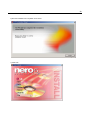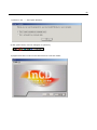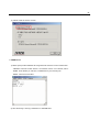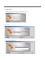
1
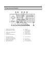
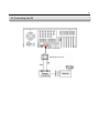
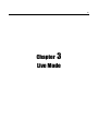
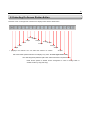
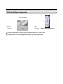
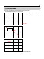
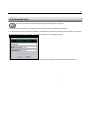
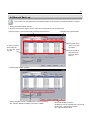
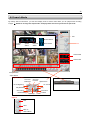
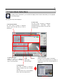
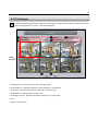
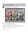
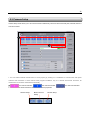
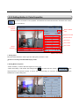
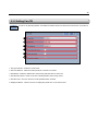
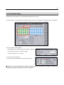
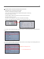
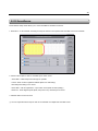
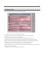
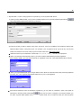
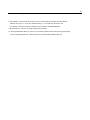
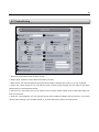
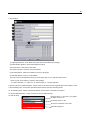
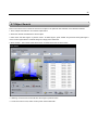
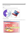
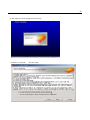
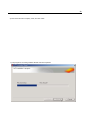
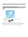
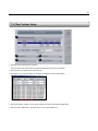
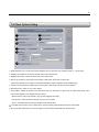
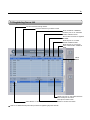
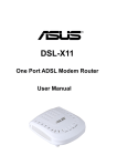
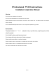
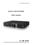
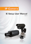
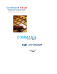
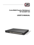
KOCOM-DVR USER’S MANUAL
2
3
Table of Contents
Chapter 1.
Chapter 2.
Chapter 3.
Chapter 4.
Chapter 5
About KOCOM DVR
1.1 Introdcution
1.2 Features
1.3 Important Notes
KOCOM DVR Unit
2.1 Unpacking KOCOM DVR Unit
2.2 Front View of KOCOM DVR
2.3 Rear View of KOCOM DVR
2.4 Connecting Sensor And Alarm
2.5 Connecting Pan/Tilt
Live Mode
3.1 Live Mode
3.2 Selecting On Screen Divison Mode
3.3 Pan/Tilt/Zoom Operation
3.4 Screen Movement
3.5 Camera/Alarm-Out/TV-Out Selector
Search Mode
4.1 Search Mode
4.2 Search Mode Option Menu
4.3 Print Images
4.4 Save Images To BMP or JPG
4.5 Selecting On Screen Division Button
Setup Mode
5.1 Setup Mode
5.2 System Setup
5.2.1 Recording & Backup Drive Setup
5.2.2 User Registration
5.2.3 Rebooting Setup
5.3 Camera Setup
5.3.1 Setting General Camera Properties
5.3.2 Setting Motion & Color Properties
5.3.3 Setting Pan/Tilt
5.4 Schedule Setup
5.5 DI Schedule
5.6 Network Setup
5.7 Control Setup
5.8 Backup Setup
-------------------------------------------------------------------------------------------------------------------------------------------------------------
6
7
8
---------------------------------------------------------------------------------------------------------------------------------------------------------------------------------------------------------------------------------------------------------------------
10
10
11
12
13
---------------------------------------------------------------------------------------------------------------------------------------------------------------------------------------------------------------------------------------------------------------------
16
17
17
18
19
---------------------------------------------------------------------------------------------------------------------------------------------------------------------------------------------------------------------------------------------------------------------
22
23
24
25
26
---------------------------------------------------------------------------------------------------------------------------------------------------------------------------------------------------------------------------------------------------------------------------------------------------------------------------------------------------------------------------------------------------------------------------------------------------------------------------------------------------------------------------------------------------------------------------------------------------------------------------------------------------------------------------------------------------------------------------------------------------------
28
28
29
30
31
32
33
34
35
36
39
40
41
43
4
5
Chapter
1
About KOCOM DVR
6
1.1 Introduction
KOCOM DVR is a computerized system that performs displaying, recording and retrieving the analog data from CCTV
onto personal computer. As it admixes advanced hardware technology and innovative software, it carries out security
taKOCOMs with high performance and maximized system stablility.
KOCOM DVR can accept up to 32 cameras on frame rate up to 480/240fps depending on model type. As KOCOM DVR
adopts high compression algorithm, it maximizes storage capability and creates less network distruption. It can create
high-quality and noise-reduced images which never lose original quality or degrade over time comparing with the analog
recorders of the past.
KOCOM DVR also allows multiple users to access local DVR through any network connection for instant live viewing and
remote search.
7
1.2 Features
▶ Max. 32-Ch camera inputs
▶ Display speed at max. 480fps / Recording speed at max. 240fps
▶ Provides Mpeg4 and Mjpeg compression algorithm
▶ High resolution at 640x480
▶ Max. 8-Ch audio recording (Optional)
▶ Various alert modes upon various events
▶ Pan/Tilt/Zoom control on both server and client side
▶ 6-level of security access
▶ Digital watermark support
▶ Dynamic IP support
▶ Multiple and simultaneous remote connections
▶ Allows access from Windows CE installed PDA through mobile internet
▶ High performance, durable rackmount case
8
1.3 Important Notes
Before Operating KOCOM Server Program
1) Recycle Bin Setup
Check on the box “Do not move files to the Recycle Bin. Remove files immediately when deleted.” in the property of
Recycle Bin.
2) Display Setup
- Set resolution at 1024x768 and High Color 16bit.
- Set “System Standby”, “Turn off monitor” and “Turn off hard diKOCOM” at “Never” in Display Properties\Power
Management Properties\Power Schemes.
3) Rebooting Setup
We highly recommend you to set automatic daily rebooting in idle time for most stable system operation.
4) Operating System
As KOCOM Software was bulit on Windows 2000 platform, it operates most stable on Windows 2000 platform.
5) DirectX
DirectX Verison 8.1b or above
9
Chapter
2
KOCOM DVR Unit
10
2.1 Unpacking KOCOM DVR Unit
Remove KOCOM DVR Unit from the package.
Make sure that the following contents are included in the package before beginning the installation procedure.
Included contents are ;
1. Mouse
2. Keyboard
3.KOCOM Software CD-Rom
4. KOCOM DVR Unit
5. Manual
6. Power Cord
2.2 Front View of KOCOM DVR
1
2
3
1. Power LED : Green light turns on when switching on.
2. HDD LED : Red light turns on when hard diKOCOM runs
3. Power switch
11
2.3 Rear View of KOCOM DVR
1
5
6
7
2
8
3
9
4
17
10 11 12 13 14 15 16
1.
Sensor Input (8 Input Ports)
10.
USB Port
2.
Camera Input (Ch1 ~ Ch16)
11.
COM1 Connector
(For PTZ device)
3.
Alarm Output (5 Output Ports)
12.
Print Connector
4.
TV Out Port
13.
COM2 Connector
5.
AC Power Socket (Power In)
14.
Line-out Connector
AC Power VAC Switch
15.
Line-in Connector
6.
(DIP Switch for 110/240 VAC)
7.
AC Power Socket (Power Out)
16.
Mic Connector
8.
PS2 Socket (Keyboard)
17.
Monitor Connector
9.
PS2 Socket (Mouse)
18
Lan Connection Port
18
12
2.4 Connecting Sensor And Alarm
[ Sensor Input Terminal ]
[ Alarm Output Terminal ]
1. Connection
1. Connection
Connect one signal lineto COM port and connect
Connect both power lines to DO terminal
Another signal line to the desired sensor number.
2. Operation
2. Operation
- Normal : DO Terminal Open
- Normal : 1-8 Terminal & COM Port Open
- Control Output : DO Terminal Close
- Sensor Detection : 1-8 Terminal & COM Port
3 D/O Voltage
Close
.DC 30V, 1A or below
3. At normal close mode, it works reversely.
.DC 110V, 0.3A or below
.AC 125V, 500mA or below
13
2.5 Connecting Pan/Tilt
COM Port (RS232C)
RS422/485 Converter
14
15
Chapter
3
Live Mode
16
3.1 Live Mode
After running KOCOM-DVR program, the below GUI immediately executes. It displays the real-time images coming from
the attached cameras and contains functional buttons for switching to other setup modes.
Camera/Alarm/TV-Out
Panel
Screen Division
Select Button
Voice
Commnication
HDD Space Indicator
For Camera Select Panel
For Alarm Panel
For TV-Out Select Panel
Auto Switching Mode Indicator
Event Detect Indicator
Client Connection Indicator
Backup Indicator
17
3.2 Selecting On Screen Division Button
Place the cursor on the right end of main GUI to display screen division select button.
10-Split
10-Split
9-Split
13-Split
16-Split
22-Split
7-Split
13-Split
6-Split
25-Split
4-Split
30-Split
1 (Displays one channel. You can select the channel on camera
36-Split
Full Screen Mode (Hides all buttons and displays only video. To return right-mouse click)
Auto Switching Mode (Selected split screen will be switched in sequential order)
Reset Screen (Return to default screen arrangement in case of moving screen to
another location by drag-and-drop)
18
3.3 Pan/Tilt/Zoom Operation
Place the cursor on the center of button of main GUI to display Pan/Tilt/Zoom control pad.
Pan/Tilt Movement
Zoom Out
Focus Far
Zoom In
Focus Near
[ Detail Pan/Tilt Control Panel ]
☞ If Pan/Tilt is connected the camera, Pan/Tilt icon will be shown on the camera view.
☞ The Detail Pan/Tilt Control Panel appears differently depending on Pan/Tilt type.
19
3.4 Screen Movement
You can freely change the location of each screen by drag-and-drop on display screen.
1. Select the screen which you want to move to another location.
CAM01
CAM02
CAM03
CAM04
CAM05
CAM06
CAM07
CAM08
CAM09
CAM10
CAM11
CAM12
CAM13
CAM14
CAM15
CAM16
☞ Applicable on KDB 050050S to 240240S models
Click
2. Drag the screen to the location that you want to move to.
CAM01
CAM02
CAM03
CAM04
CAM07
CAM08
CAM16
CAM05
CAM06
DragCAM09
CAM10
CAM11
CAM13
CAM14
CAM15
CAM12
3. Drop the screen to the location where you move to.
CAM16
CAM02
CAM03
CAM04
Drop
CAM05
CAM06
CAM07
CAM08
CAM09
CAM10
CAM11
CAM12
CAM13
CAM14
CAM15
CAM01
You can return back to default status clicking reset button on screen division select button.
20
3.5 Camera/Alarm-Out/TV-Out Panel
1. Camera Select Panel
On each split mode of screen, clicking one channel button will show the split mode including the channel clicked.
(ex : If on 4 split mode with 16 ch inputs, clicking no. 1 channel will display no.1 to 4 ch and clicking no. 5 will be no.5 to 8
ch.)
In case of over 16 cameras connected, you can switch from no.1 to 16 to no.17 to 32 by clicking the arrow button on the
right.
2. Alarm Panel
Shows alarms connected. Clicking each alarm no. will send alarm out.
3. TV-Out Panel
Shows the current channels viewed from TV monitor.
☞ Applicable on KDB 050050S/4CH to 240240S/16CH models
☞ Only the channel checked on “Enable AV-Out” in Camera Setup Mode will be displayed through TV monitor.
21
Chapter
4
Search Mode
22
4. Instant Replay
This function enables the playback on one channel selected for the recent time selected while on live mode.
1. Click the camera view that you want to play.
2. Press Instant Replay Button.
3. Then playback for the selected channel will be run in pop-up window on live mode as shown below.
4. To change the previous time of reply (1 to 60min), select from pull-down menu. The change will effect from next run.
☞ To view the video in other time, stop playing and select the time in the below list. And press play button again.
☞ Previous time for instant reply can be set from Previous Time Selection Bar. The setup will effect when next
instant reply run.
23
4-2 Emergency Recording
This function enables the current recording mode to switch to continuous recording and higher frame rate
recording while the button is pressed in the emergent case.
1. Emergency Recording Setup should be done first..
2. You can enter the Setup by moving to “Recording Schedule Setup\Emergency Recording Setup” or right-mouseclicking on Emergency Recording Button. Check on video channels to run emergency recording on and set emergency
frame rate each. Or if you want to apply the same frame rate to whole channels, check on “Apply All(fps)”, then set frame
rate.
3. While in emergency recording mode, the recording will be by the frame rate set from “Emergency Recording Setup”
contiously. For stopping emergency recording, press the button again.
24
4-3 Password Lock
This function switches to password protection mode after the button is pressed.
1. Press Password Lock Button once. Whole function modes will require password input afterward.
2. In order to enter ID and PW when KOCOMed for. One default ID (Administrator, Manager and General) can be chosen
from the pull-down list. Or you can write your own ID registered on User Registration Menu.
3. To be released from Password Lock Mode, press the button once again and complete ID and PW confirmation.
25
4.4 Manual Back-up
This function is for manual backup to the specified folder in local hard drive, CD-RW, DVD Writer or CD-Rom.
1. Simply press Manual Back-up Button.
2. Then the below backup program will run. Select the recording files to back up after search.
Specify the period / video channles with recordings and click search
To select all files to
press Select All
To view file, press
Preview
Automatic search period select
Click each title in
order to sort files
by subject.
Shows recording
files after search.
Select the files to
back up.
3. Select backup location as below.
Specify the folder in local or network hard to back up recording
files. If DVR or CDRW is installed, press DVD or CDRW.
Back : start backup procedure
AVI Backup : back up selected files to AVI format
Backup Stop : stop backup procedure
Exit : exit from Backup Menu
26
☞ Concerning backup method to DVD or CD-RW, refer to the CD-RW backup manual provided seperately.
☞ To view backup recording files, use DVRPlayer.exe from C:\KOCOM-DVR\Tools. See page 58 to know the
usage.
You can also use separate player installation version to play back-up files from other PC without DVR program.
27
4.5 Search Mode
By clicking search mode button, you shift from display mode to search mode where you can playback the recording
images. ※ Default is no image with 4-split mode. Click play button and select your desirous split mode.
Detail A : Playback Status Indicator
Exit
Normal Search
Volume
Status
Speed
Status
Playback
Status
Event Search
A
Search Date
Search Time
Screen Division
Select Button
Playback Control
One Hour
Backward
One Hour
Forward
Camera Selector
Speed Down
Go To Beginning
Go To End
Play Backward
One Frame
Backward
Stop
Play
Speed Up
Detail A
Print
Save
Back To
Search Menu
Pause
One Frame
Forward
28
4.6 Search Mode Option Menu
By clicking search mode button, you can shift from display mode to search mode where you can playback
the recording images.
Then playback setup will be displayed ;
1. Date Selection Menu
The date having recording is displayed
colored. Click the date that you want to
search from.
5. Video Information
Check on each to displayed
resoultion, codec type or recording
type on recording images.
2. Search Time
The time having recording is displayed
colored(FPS:Green,
Motion:Blue,
AlarmIn:Orange). Move the red bar to the time that
you want to play.
3. OK
7. Cancel
Click to play
selected images.
6. Preview Window
Displays the preview images of recordings.
In order to view preview from the camera of
specific time, click on the corresponding time on
camera line.
4. Display Event
Click each on Motion or Sensor-in
Option to display only event recording
footages.
Click the button next to View Detailed
Event. Then event viewer will run.
Event Viewer
29
4.7 Print Images
To print the images being displayed, simply press PRINT button. Double-click each image to select the images to
print. Set printing options as you like. Then click PRINT utton.
`
1
3
2
5
Image
selected
6
7
1. Recording date : shows the date and time of recording image
2. Printer Selection : enables the selection of printer installed on your Windows
3. Copy Count : can select the number of copies that you desire to print
4. Image Border : creates border line of paper used
5. Image Per One Page : specifies the number of images on one page to print
6. Print
7. Exit from the print menu
4
30
4.8 Save Images To BMP/JPEG/AVI
To save the images being displayed, simply press SAVE button. Double-click each image to select the images to
save to BMP/JPEG/AVI. Set the options as you like. Then click SAVE button.
1
2
4
3
Image
selected
5
6
7
8
1. Destination : specifies the folder where the files are saved.
2. Format : can select the format of images saved (BMP, JPEG or AVI)
3. Save Info : check to display the image information of the image saved
4. Watermark : check to add digital watermark on the image saved (applied to BMP image only).
5. Move Image : click right or left arrow button to move selected channel to next or previous frame (check on “Move All”
to move all channels at the same time).
6. Next Frames: Save next frames to the frame shown with the number set
7. Save
8. Exit from the print menu
31
4.9 Selecting On Screen Division Button
Place the curosr on the right end of playback screen to display screen division select button.
10-Split
10-Split
9-Split
13-Split
16-Split
22-Split
7-Split
13-Split
6-Split
25-Split
4-Split
1 (Displays one channel. You can select the channel on camera
30-Split
36-Split
Panorama Search
32
Chapter
5
Setup Mode
33
5.1 Setup Mode
Setup mode allows you to adjust schedules and system properties and more. In order to enter setup mode,
simply click SETUP botton.
5.2 System Setup
1
2
3
4
6
5
7
1. System Information : shows the details of your system. Use the scroll bar to view the content to the end.
2.HDD DiSK Information : shows current recording and backup drives setup.
3. System running mode : selectable between “normal mode” and “DVR mode”.
1) Normal mode : loads items before running KOCOM-DVR program.
2) DVR mode : hides top items before running KOCOM-DVR program. Exiting program shuts down Windows
automatically.
4. User registration : sets 6 user access levels.
5. View log file : displays the system log file.
6. Reboot setup : sets daily, weekly or monthly schedule of system rebooting or shut-down.
7. Run Virtual keyboard : runs virtual keyboard
34
5.2.1 Recording & Backup Drive Setup
When you run KOCOM DVR program first after installation, Recording Drive Setup will pop up, where you can set the
recording and backup drives.
In order to add the recording & backup drives to the current setup, enter SETUP Mode. Then click MODIFYING
button in system setup menu.
1. Select the drive displayed in the list by clicking on it.
2. Then select the recording type among recording or backup. Click apply.
3. Repeat step 1 and 2 in order to add more recording or backup drives.
4. Click OK to finalize the setup.
35
5.2.2 User Registration
KOCOM DVR program provides 6 user levels to limit the access for program operation. User levels are adminstrator,
manager, general, custom1, custom2 and custom3. KOCOM DVR program is initially set with Adminstrator ID, which can
control all functions.
In order to prevent someone from operating the program or to modify the current setup, simply click USER
SETUP button in system setup menu.
1. Registering new user on the list or delete
Click blank line. Then double-click on the User ID column to enter new ID and Password. And select one level among 6
levels. Additional 17 new users can be registered, which makes total 20 users. Clicking the trash button on the left
deletes the User.
User Share
2. Setting Current User
Initially user ID is set at Administrator. If you select another user as “Current User” and exit User Setup menu, the
program will ask the user for password unless the user is authorized with the corresponding functions.
User Share
3. Setting User Fixed
Set another user as “User Fixed” on the list and exit the setup. Then the program will return to surveillance mode and
Current User will switch to the user level defined as “User Fixed” automatically after the time of no-input on Setup Mode,
which can be set on “User Fixed Delay Time”.
User Share
36
4. Authorizing each 6 user level
In order to set authorithy of indivisual user level, click each user level and check on the box of each fuction as below.
☞ Adminstrator, Manager and General are not allowed to be modified by user’s own.
After user setup is done, click OK button in order to finalize the setting. If not, click Exit button.
5.2.3 Rebooting Setup
To set periodical system reboot or shut-down, simply click REBOOT SETUP button.
Checking on “Auto Reboot” and on one of Every day, Every week or Every month. Then set the time, day or date. Then
exit to finalize the setup. The program will perform scheduled rebooting.
If “System Down” is checked on together, the system will be automatically shut off as scheduled.
37
5.3 Camera Setup
Camera Setup mode allows you to set camera functions indivisually. There are three functional parts, General, Motion &
Color and Pan/Tilt.
1
2
1. You can select indivisual camera button to set its property by clicking on it. Doubleclick on camera button will repeat
activation and inactivation of each channel. After program installation, only no.1 channel will activate. Therefore, all
camera buttons should be doubleclicked indivisually.
☞
: the channel selected ,
: the channel activated ,
2. Click one of three functional buttons in order to set camera properties.
General Setup
Motion & Color
Setup
Pan/Tilt Setup
: the channel inactivated
38
5.3.1 Setting General Camera Property
In order to set general camera properties, click GENERAL SETUP button and select each camera icon on
the above.
1
2
3
4
5
1. Camer Name : enter the camer name desired to be displayed on the image. The font color can be change by clicking
color button on the right end.
2. Display Camera Name : check on the box to display the camera name.
3. Enable AV Out : check on the box to allow the camera to be view through TV monitor.
4. Display Audio Button : check on the box to display audio icon on camera view as the below picture.
Camera Name
Audio Button
5. Video Loss Surveillance : check on each option to enable sending alert when there is no video signal
- Sound Alert : makes beep sound through PC speaker
- E-mail : sends e-mail upon video loss (Refer to E-mail Setup)
- Phone Alert : calls to registered no. upon motion event (Refer to Dial-up Setup)
39
- Alarm-Out : sends digital outputs (alarm, lamp and so on) checked upon video loss
5.3.2 Setting Motion & Color Properties
In order to set motion & color properties, click MOTION & COLOR SETUP button and select each camera
icon on the above.
Color setting
preview
window
Back to default
color
Brightness control
Contrast control
Hue control
ChrU control
ChrV control
Motion
sensitivity
Motion area setting
1. Setting Color
Move the below slide bars in order to get color setting that you desire to have.
☞ Select on Overlay from KDB 480S Display model.
2. Setting Motion Properties
- Motion sensitivity : move the slide bar ranges from Low to High
- Motion area setting : Click motion area setting button [
] and select the size of brush [
]. Then
drag the brush on the preview window. To set the area, leftmouse-drag. Or cancel the area, rightmouse-drag. Blue
shaded area is motion setting area.
40
5.3.3 Setting Pan/Tilt
In order to set pan/tilt properties, click PAN/TILT SETUP button and select each camera icon on the above.
1
2
3
4
5
6
1. RX Type Selection : Select the model of RX.
2. Out Port Selection : Select the COM port which connects to converter.
3. RX Address : Select the Address No. which exactly matches with one of the RX.
4. Pan/Tile Auto Mouse : Check on the box to enable pan/tile control using mouse.
5. Pan/Tile Invert : Check on the box to make pan/tilt direction inversed.
6. Display RX Button : Check on the box to display the pan/tilt icon on the camera view.
41
5.4 Schedule Setup
Schedule Setup mode allows you to set recording schedule for each camera.
1. Select camera no. to set schedule. And drag and drop the mouse on the specific DAY and TIME zone to set schedule.
2. Set the detailed recording options.
- Set resolution one of “160x120, 240x180, 320x240 or 640x480)
- Set compression type one of “Mpeg4 or Mjpeg”
- Set video quality from “Low” to “High”.
3. Check on each recording type
(DI, Motion, Audio Recording and Audio Event Recording).
※ Checking on Audio Recording will enable recording sound from microphone. Checking on Audio Event
Recording will trigger recording when audio event happens.
42
※ Click Action button to select alert mode when motion event occurs.
- Display Motion Areas : makes motion area blue shaded
- Sound Alert : makes beep sound through PC speaker
- E-mail : sends e-mail with captured image to registered address (Refer to E-mail Setup)
Alert delay time setting is 5 to 30 sec
- Full Screen Display : displays one full screen of the camera view with motion event
Alert delay time setting is 5 to 30 sec
- Phone Alert : calls to registered no. upon motion event (Refer to Dial-up Setup)
- Alarm-Out : sends digital outputs (alarm, lamp and so on) checked upon motion event
4. If you don’t check on Motion Recording, set frame per second on FPS Recording slide bar. Another slide bars is
inactive.
If you check on Motion Recording or DI nos, set frame per second for event recording on FPS Recording slide bar and
set non event frames on Non-event FPS slide bar.
For recording upon event
For recording without event
43
Pre Alarm : start recording specific frames ahead upon event.
- Mpeg4 : 0 to 2 key frames
- Mjpeg : 0 to 30 frames
Recording Delay Time : start the recording specific seconds afterwards upon event
- Range : 0 to 5 seconds
Audio Sensitiveness : 0 to 25
※ You can repeat the step 1 to 4 in order to set schedule on multiple DAY and TIME zones.
5. Click Exit button to save and exit.
44
5.5 DI Surveillance
DI Surveillance Setup mode allows you to set DI surveillance schedule for each DI.
1. Select DI no. to set schedule. And drag and drop the mouse on the specific DAY and TIME zone to set schedule.
2. Check on alert option in order to send alert upon motion event.
- Sound Alert : makes beep sound through PC speaker
- E-mail : sends e-mail to registered address (Refer to E-mail Setup)
Alert delay time setting is 5 to 30 sec
- Phone Alert : calls to registered no. upon motion event (Refer to Dial-up Setup)
- Alarm-Out : sends digital outputs (alarm, lamp and so on) checked upon DI event
3. Click Exit button to save and exit.
※ You can repeat the above steps in order to set schedule on multiple DAY and TIME zones.
45
5.6 Network Setup
Network setup mode enables you to set every network-related properties.
○1
○2
○3
○4
○5
○6
○7
○8
○9
1○0
1. Lan : check on to allow video image transmisstion through TCP/IP.
☞ Default video port is 8100. If you want to change, enter another port no. And restart the program.
2. Web : check on to allow remote access through web browser
☞ Default web port is 80. If you want to change, check on “Port Setting Option” and enter new port no.
☞ Please make sure that video and web port (8100 & 80) are forwarded to the DVR if there is router or firewall.
3. Modem : check on the box and choose the corrent type of modem that you use for modem-to-modem connection.
4. Serial Network : check on the box and choose COM Port No. to communicate through serial port
5. Audio Port Setting : set the port for transferring sound to remote site. Default port is 8200.
6. Network Image Quality : you can set the image quality trasferred via internet using adjustment bar. The higer the
image becomes, the bigger the size gets.
Totel Speed Limit : you can set total transfer frame rate allowance.
46
7. Dynamic DNS : In case of using dynamic IP or private IP, you can Dynamic DNS service.
1) Unless you have DDNS ID/PW, you can move to DDNS register menu by pressing DDNS Register Button
.
Then below DDNS Register Menu will show up as below.
2) Enter the ID that you like to register. Then press “ID Check”. If the ID is available, enter Password, Email, DVR
Name and DVR Location. Then press “Done”. For example, if “dvr” is registered as ID, only the ID “dvr” can be used
instead of IP address from remote client program. And web client URL is http://godvr.net/dvr
☞ DDNS ID can be up to 20 characters. It will accept “a – z”, “0 – 9”, “-“ and “_”. And will not accept space.
☞ When you unistall and reinsall DVR program, you need to retrieve DDNS ID/PW previously registered.
Press “Retrieve DDNS”. And enter the ID and PW you registered. Press “OK”. Then DDNS ID/PW will be restored.
☞ When you forget DDNS ID/PW, press “Forgot ID/PW” button. Enter the e-mail and DVR name previously registered.
And press “OK”. Then registred DDNS ID/PW will be sent to your e-mail registered.
☞ If the DVR is behind the router or firewall (IP is private IP), you can check on “Shared IP” option. Then public IP
information in the DVR will be automatically updated every one hour when it changes. For manual IP update, you
can press “Dynamic DNS Update” button
. Please make sure to forward the video and web port (8100
47
and 80 if unchanged) to the DVR from router.
8. Voice Netwok : check on the box for two-way voice communication and enter the name desired.
Transmit voice upon 1:1 voice call : enables allowing 1: 1 voice talk only with client’s call.
Port Setting : set the port used for transferring voice. Default is TCP8500/UDP8500.
9. PDA Connection : check on to enable access from PDA client
10. Smart-Update Before Start-up : check on to use Smart Update function before running the program.
Execute Smart-Upgrade Now : click the button to run instant Smart Updated right now.
48
5.7 Control Setup
1
2
3
5
4
6
7
8
12
9
10
11
1. Server ID : Enter Server ID that you desire to have.
2. Video Format : Select the correct video format used in your area.
3. Alarm Sound : Can select the WAV file which gives alert through PC speaker upon events. Or you can use default.
4. Sensor List : Shows sensor list. You can enter the name of sensor instead of DO##. And can select the type Open
(Normal Open) or Closed (Normal Closed).
5. Alarm-out List : Shows alarm list. You can enter the name of sensor instead of DI##. And can select alarm delay time
from 0 to 30 seconds.
6. Audio List : Shows audio list. You can enter the name of sensor instead of Audio##. And can camera no. to be mixed
with the audio recording. You must select camera no. per each audio port in order to use audio function.
49
7. E-mail Setup :
1
2
3
4
5
6
7
1) Outgoing Mail Server : Enter SMTP mail server that the mail will be sent through
2) Authentification Method : Select authentification method
3) Account Name : Enter the account name
4) Account Password : Enter the account password
5) Encoding Method : Select the suitable one with your language
6) User Mail Address : Enter you mail address
7) E-mail : Enter e-mail addresses which get e-mail report upto 10 nos upton the below events.
Check on each event options to report to each recipient.
- M : Motion detection / V : Video Los / D : Sensor Event / S : Program start/end
8. Send E-mail Upon System Start/End : Check on the box to send e-mail to recipients when system starts or ends
9. Auto Switching Time : Set the time interval between screens when auto switching mode
10. AV Switching Time : Set the time interval between screens when connected to AV monitor
11. Record While Searching : Check on the box to record while searching
12. Dial-up Setup
Enter the phone no. and click (+) to register
To delete, click (-) icon.
Shows the phone no. list
Shows the modem list on the DVR
Sets the ringing time
50
5.8 Backup Setup
1. Automatic Backup
1. Check on “Perform Backup” to perform backup scheduled.
2. After checking on “ Every day, Every week or Every Month”, set date, day or time.
3. Check on “Before one day, Before one week or Before one month” from Option.
4. Select the channle no. that you want to backup
5. In order to erase older datas, check on “If hard drive is full, delete old file”.
51
2. Manual Backup
Run “KOCOM-DVRBackup.exe” in “C:\KOCOM-DVR\Tools” folder in order perform backup manually.
Then the below backup program will run.
Specify the period with recordings and click search
Automatic period select
Click each title in order to sort
files by subject.
Shows the recording files after
search. Select the files to
back up.
Specify the folder in local or network hard to back up recording
files. In case of DVD writer installed, DVD can be selected.
After selecting files to back up, click Backup.
52
3. Viewing the backup files
Run “KOCOM-DVRPlayer.exe” in “C:\KOCOM-DVR\Tools” folder in order play backup files.
Select the folder where backup files exist
Doubleclick on the file you want to play from the list.
Then KOCOM-DVRPlayer will run instantly.
KOCOM-DVR Player
53
4.4 Add To Bookmark / View Bookmark List
Add To Bookmark
1. Select the specific camera view and click “Add To Bookmark Button”
2. Enter the remarks in the blank. And clieck “Add”.
3. Then the bookmark will be saved on the bookmark list.
View Bookmark List
1. Click “View Bookmark List Button” to search and view bookmarks
2. Select specific channel or whole channles, and the period to search bookmarks.
3. Click “Search”. Then bookmarks will be listed as shown below.
4. Select one bookmark and click “Go”. Then the selected image will be played in one-split mode.
☞ To delete the bookmark , select one and press delete button. You can select multiple bookmark by using Ctrl or Shift
54
Key together.
☞ To edit the remak of the bookmark, press “Edit” and change the remark.
4.5 Search Option Menu
By clicking search mode button, you can shift from display mode to search mode where you can playback the recording
images.
2. Search Time
The time having recording is displayed in color
(FPS:Green, Audio:Yellow, Motion:Blue, Sensor1. Date Selection Menu
In:Orange). Move the red bar to the time that you
The date having recording is displayed
want to play.
colored. Click the date that you want to
※ You can check or uncheck on the box next to
search from.
camera name to select channels to play.
Then playback setup will be displayed ;
Click the button to
keep viewing the
playback setup menu
before running search
mode.
6. Video Information
Check on each to
displayed resoultion,
codec type or recording
type on recording
images.
3. OK
Click to play
selected images.
4. Event Search
See page 27 for details.
7. Preview Window
Displays the preview images of recordings.
In order to view preview from the camera of
specific time, click on the corresponding time on
camera line.
5. Object Search
See page 28 for details.
55
4.7 Object Search
This function allows user to search the movement of object in the particular area selected on the date/time selected.
1. Press “Object Search Button” from Search Option Menu.
2. Select the channel and date/time to search object.
3. Press “Add” and draw regions on preview screen. To delete regions, press “Delete” and just draw rectangular regions
on the current regions drawn. To delete all regions, simply press “Delete All”.
4. Press “Search”. Then search result will be shown on Motion Event List as shown below.
☞ Selecting one event from the list will show the image on preview screen.
☞ To add one event to book, select one and press “Add To Bookmark”.
56
BACK-UP USING CD-RW OR DVD-RW
1. Media
You can use CD-RW if the recorder is CD-RW. Or use DVD-RAM if it’s DVD-RW.
CD-RW
DVD-RAM
2. CD-RW Program Installation
1) If CD-RW is installed, you can install INCD. Or if DVD-RW is installed, please install DVDFORM program. After
inserting Nero Install CD, select InCD.
57
2) Click “Next” upon InCD Updater screen comes up.
3) Check on “I accept all ……” and click “Next”.
58
4) Enter User name and Company name, and click “Next”.
5) The program is now being installed. Please wait until completion.
59
6) Now the installation has completed. Click “Finish”.
7) Click “Exit”.
60
8) Check on “Yes, ….”. Then system will reboot.
9) After system reboots, InCD icon will appear on system tray.
10) Right-mouse-click on InCD icon and click Version Info. Then click “Detail”.
61
11) Please check the version of InCD.
3. CDRW.ini File
1) Please open provide CDRW.ini file using Note Pad. Enter the correct of information.
- VERSION : enter the current version. If it’s 3.XX.XX, enter 3. Or if 4.XX.XX, enter 4.
- NAME : enter INCD if you use Nero, or DIRECTCD if your use Easy CD.
- DRIVE : enter the current drive.
2) Save the change. And copy CDRW.ini to C:\KOCOM-DVR.
62
4. Formatting the Media
1) After inserting new media, InCD program will run automatically. Click “OK”.
2) Click “Next”.
3) Select RW drive and click “Next”.
63
4) Click “Next”.
5) Select “Format” if the media is new.
6) Now the media is being formatted. Required time is 30 to 40 minutes. Do not eject CD while formatting.
64
7) Format completes. Click “OK”.
8) Then you can check the free space of the media from Windows Explorer.
65
5. Back-up FROM KOCOM-DVR Backup
1) Run KOCOM-DVRBackup.exe from C:\KOCOM-DVR\Tools. Then the backup program will run.
2) Press “CDRW” button.
66
3) Select .mmv files to backup using drag & drop mouse or multiple selection with Ctrl or Shift key.
4) Press “Backup” and click “Yes” if you want to copy KOCOM-DVRPlayer setup file to the CD-RW.
67
5) Now backup is running.
6) Backup will complete. Press “OK”.
68
6. DVD-RW Program Installation and Backup
1) After inserting DVD program CD, the install program will run automatically. Press “Install” button.
2) Click “Next”.
69
3) Click “Yes”.
4) Click “Next”.
5) Click “Next”.
70
6) Click “Next”.
7) Now being install. Please wait until completion.
8) Click “Finish”.
71
9) It will search for DVD-RAM Device. Then press “Yes”. System will reboot.
10) After reboot, check if DVDForm program appear.
11) After running DVDForm program, press “Start” to start formatting if the media is new.
72
12) Now the format is on progress.
12) Format completes. Press “OK”.
13) The method of backup with DVD-RW is the same as with CD-RW. But no need for copying CDRW.INI to
C:\KOCOM-DVR. Run KOCOM-DVRBackup.exe from C:\KOCOM-DVR\Tools. Then DVD button will activate
when the formatted media is inserted.
73
14) Press “DVD” button. Select .mmv files to backup and press “Backup” button.
Chapter
7
Network Function
74
7.1 Remote Client Program
You can view the images from remote site using Remote Client Program. First install Remote Client Program using setup
file in the cd-rom provided. After the installation, run KOCOM-DVR Client.exe or KOCOM-DVR Client shortcut created on
the desktop. Then the below display mode will come out.
Exit Button
Search Button
Setup Button
Voice Communcation
Recording Button
Connection Button
Pan/Tilt Control
Panel
Screen Split
Selection Button
▶ Video Channel Selection ; Select remote video channels to view on the selected screen division.
▶ Video Channel ON/OFF ; Select remote video channels to receive image. ON is filled with blue color.
OFF is blank inside.
▶ Audio Channel Selection ; Select remote audio channels to listen. Blue-circled are availabe video
channels mixed with sound. When selectd, the button will be filled with blue color. Only one audio channel
can be selected.
75
7.2 Connecting From Remote Client Program
In order to server, just click CONNECTION BUTTON. Then the below dialog box will come out.
1. Select Server Name from the list.
2. Enter ID and Password, which should be registered on User Registeration Setup from server side.
3. Click connection button in order to connect.
4. Click cancel button to cancel.
☞ LAN check box from Network Setup on server side should be checked on to allow remote access.
☞ Please make sure that video port 8100 (if not changed from server side) is forwared to the DVR if it’s behind router or
firewall. And make sure to check on “Share IP” option so that server program can get correct global IP information.
☞ In order to view images through remote client, Direct X 8.1 or above should be installed on client PC.
76
7.3 Client System Setup
1
2
3
4
5
1. Recording Drive Information and Setting
You can set the drive where real time images transferred from server are recorded.
2. View System Log : Displays the system log file.
3. View Event Log : Shows the below event history created from server side instantly
[ Event Log Viewer ]
4. Use Smar Update : Check on to run Smart Update upon start-up of KOCOM-DVR Client
5. Execute Smart Update Now : Click the button to run Smart Update now
77
7.4 Client Option Setting
1
2
3
4
5
6
7
8
1. Dislay Rotation Time : Set the time interval between each screen when auto switching mode (1 – 30 seconds)
2. Display Camera Name : Shows the camera name on the camera view
3. Display Frame View : Shows the frame rate on the camera view
4. Event Log Recording : Records the event history created from server side on the log file
(The event histories are recorded in C:\KOCOM-DVRClient\LogFile named like Event2003XXXX.log)
5. Check on Voice Network to enable Voice Communication with server and enter the name desired
6. Recording Type : Check on one of two options
7. Event Alarm : Makes the selected one channel to pop up in full screen for given time or makes beep alarm, when
motion event happens from selected remote channel.
- Select Camera : select one channel to pop up when triggered by motion
- Pop-up (Sec) : select the time to maintain pop-up (3~10 seconds)
- Sound : send beep alarm through PC speaker on the remote client.
☞ To enable motion event pop-up or beep alarm, motion recording mode should be set from remote DVR.
8. Auto Login After Disconnected : Connects again to remote DVR automatically after disconnection.
78
7.5 Registering Server List
For the connection through TCP/IP
Enter the name that you desire to have
Enter IP address or DDNS ID.
Enter the port no. for video data
transfer. Default is 8100.
Check when the server is registred
to DDNS.
Enter the port no. for audio
transfer. Defaulit is 8200.
Enter the port no. for two-way
voice communcation. Default is
8500.
Delete
Button
Select Com port no. and select baud rate
when serial port connection
Select Modem or Serial
Enter phone number when
modem-to-modem connection
☞ Refer to 5.6 Netwrok Setup about the procedure of registering Dynamic DNS ID.
79
☞ You check video, audio and voice port no. from server side Network Setup if changed from the default.
7.6 Viewing Remote Recordings
In order to view remote recordings, just click SEARCH BUTTON. Then the below dialog box will come out.
Select date & time. Then click OK to continue remote playback.
1. Date Selection Menu
The date having recording is displayed
colored. Click the date that you want to
search from.
2. Search Time
The time having recording is displayed colored (FPS:Green,
Motion:Blue, Alarm-In:Orange). Move the red bar to the time
that you want to play.
5. OK
3. Video Information
Check on each to displayed resoultion, Click to play
selected images.
codec type or recording type on
recording images.
Upon pressing OK button, the search interface will run.
6. Cancel
4. Record Source
Select one of Network Record Data
Or Client Record Data
80
7.7 Viewing Through Web Browser
Type IP address of the remote DVR or http://godvr.net/DDNS ID from web brower. Press “Enter”.
Ex) If IP address is 211.211.204.205, URL is http://211.211.204.205. If DDNS ID is dvr, URL is http://godvr.net/dvr.
Enter ID/PW from the dialog box. Press Connect button. Then web client page will show up.
☞ LAN and WEB check box from Network Setup on server side should be checked on to allow web client access.
☞ Please make sure that video port 8100 and web port 80 (if not changed from server side) are forwared to the DVR if
it’s behind router or firewall. And make sure to check on “Share IP” option so that server program can get correct global
IP information.
☞ In order to view images through web brower, Direct X 8.1 or above should be installed on client PC.
81
☞ When ActiveX download is blocked from Win XP SP2, please follow the below steps.
1. Open Internet Properties. And press "Custem Level" from "Security" tab.
2. Check on "Prompt" under "Download unsigned ActiveX controls". Press OK. And press OK from Internet Properties.
3. Then prompt window will be shown to ask if users wants to download ActiveX controls for running web client.