1
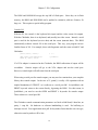
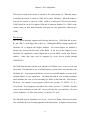
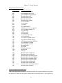
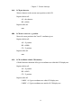
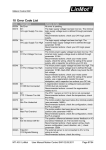
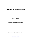
Chickadee XL User's Manual Addendum
by Ivan L. Baggett
Rev. 1.0 10/30/98
Rev. 1.1 11/16/98
Copyright 1998 Bagotronix
All rights reserved
The material presented in this document is the intellectual property of Bagotronix, except for
material furnished by others where indicated. No part of this publication may be reproduced or
distributed in any form or by any means, or stored in a data base or retrieval system, without
the prior written permission of Bagotronix.
Bagotronix
1019 Crossing Brook Way
Tallahassee, FL 32311
850-942-7905
Chapter 1: Introduction
1
2
Chapter 1: Introduction
What is this document?
This document describes the Chickadee XL, therefore it is an addendum to the Chickadee
User’s Manual, which should be referred to for additional information.
What is the Chickadee XL?
The Chickadee XL is a version of the Chickadee single board computer with the XL
configuration. The XL configuration consists of General Software BIOS and DOS-ROM, a
128K flash disk, and 512K SRAM. A second RS-232 port may also be installed, depending on
customer preference.
Why BIOS and DOS?
The purpose of having BIOS and DOS in an embedded computer is to facilitate the
development of application software. The task of software development is eased by the use of
low cost, familiar software tools such as Borland C/C++, Microsoft C/Visual C++, or
Microsoft QuickBasic. These compilers, and many others, produce an executable (EXE)
output program. In order to run an EXE, a file system and some type of file storage medium
are required. The file system is provided by DOS-ROM and the storage medium is provided
by BIOS flash disk support.
Why does an EXE require BIOS and DOS?
An EXE is a relocatable program. The final output program from the compiler is not fixed to
run at a particular address in memory. When the program is loaded, it is the job of DOS to
choose where in memory to load the program. Then DOS must “fix up” the code as it is
loaded to run at the address DOS has chosen. Once the program is loaded, it may make use of
hardware, such as input from a keyboard, output to a screen, reading and writing to disk
drives, etc. To do this, the program will interact with DOS and/or BIOS. The BIOS provides
the program with a software interface to the low-level hardware, isolating your program from
variations in hardware design. For example, to set the time of the real-time clock, you would
call BIOS interrupt 1Ah, function 03h. Using this BIOS function, your program would
function identically on a Chickadee as on the PC, even though the Chickadee uses a completely
1
Chapter 1: Introduction
different real-time clock than the PC. Another reason BIOS and DOS are needed is that your
compiler’s library has many functions which make calls to BIOS and DOS, such as console
I/O, file operations, date/time functions, etc.
What languages can I use with the Chickadee XL?
You can use any programming language which meets all the following criteria:
•
Is a compiled language that produces a stand-alone EXE that runs under DOS
•
Produces 16-bit code for 8086 or 80186
•
Has I/O read, I/O write, and call interrupt functions
All C/C++ compilers, Turbo Pascal, and compiled QuickBasic qualify. The low-level I/O
driver source for the Chickadee is in C/ASM, therefore direct access to the hardware is feasible
only in C. However, other languages may call the Feature Interrupt (Chapter 5) for an efficient
software interface to the hardware.
Organization
The organization of the Chickadee XL User's Manual Addendum is divided into several
chapters. To set up the Chickadee XL for software development, see Chapter 2: Setup. The
Chickadee XL configuration is described in Chapter 3: XL Configuration. Procedures for
writing, compiling, and debugging application software are covered in Chapter 4: Software
Development. Usage of Chickadee hardware is detailed in Chapter 5: Feature Interrupt.
Throughout this manual, it is assumed that you have some experience in programming and PC
usage. The development process involves these steps:
1) Design or acquire your application's I/O hardware (sensors, switches, relays, solenoids,
etc.)
2) Connect the Chickadee to your application's I/O hardware and the PC serial port
3) Write and debug your application
2
Chapter 2: Setup
3
4
Chapter 2: Setup
Overview
This chapter tells you how to set up the Chickadee for development activities. You are
probably eager to get started on your design project, but please take time to read this chapter
first.
Since the Chickadee does not have a keyboard and screen like a PC, “console” I/O is redirected
to a serial port.
What you Need
To develop your application software you need at least the following items:
1) Chickadee XL
2) Example programs on floppy disk
3) DB9F to DB9F null-modem serial adapter (crossover cable)
4) JP11 cable for Chickadee (if not using a serial port on a PC/104 expansion card)
5) Your compiler
6) PC with an available serial port
7) DC power source with red and black wires for attachment
How to Connect It All
There are two different setups. The first is if you are using the first serial port on the
Chickadee as the console. The second is if you are using a serial port on a PC/104 expansion
board as the console.
Console port on Chickadee:
1) Place the Chickadee on the table. Verify that standoffs are installed on the bottom side of
the Chickadee to prevent direct contact of the circuit board with the table surface.
2) Connect a red wire to JP12 pin 1. This is the positive (+) power supply feed.
3) Connect a black wire to JP12 pin 2. This is the negative (-) power supply feed, also called
“ground”. Note: instead of the connections to JP12 pin 1 and JP12 pin 2, you may connect
+5V to JP6 pin 4 and ground to JP6 pin 2, respectively.
5
Chapter 2: Setup
4) Connect the other end of the red (+) wire to the positive (+) terminal of your power
source. If the voltage regulator option is installed, the power source may be in the range of
7 to 26 VDC. If the voltage regulator option is not installed, the power source must be 5
+/- 0.2 VDC. Any voltage beyond these ranges may result in damage or improper
operation of the Chickadee.
5) Connect the other end of the black (-) wire to the negative (-) terminal of your power
source.
6) Turn the power source on. The red LED “RESET IND” should illuminate for a fraction of
a second, then extinguish. If it glows steadily or flickers, the voltage may be too low.
7) Turn the power source off.
8) Connect the DB9F to DB9F null-modem serial adapter (crossover cable) to your PC. If
your PC’s serial port does not use a DB9M AT-style serial connector, you will need an
adapter.
9) Connect the JP11 cable to the Chickadee serial port at connector JP11.
10) Connect the other end of the JP11 cable to the free end of the DB9F to DB9F null-modem
serial adapter. Go to the section “Checking it Out”.
Fig. 2-1: Chickadee XL Development Setup
Console port on PC/104 expansion board:
1) Follow steps 1 - 9 of the “Console port on Chickadee” procedure.
6
Chapter 2: Setup
2) Attach the PC/104 expansion board to the Chickadee with standoffs. Be sure to engage all
PC/104 connector pins.
3) Verify that the interrupt jumpers and I/O address dipswitches on the PC/104 expansion
board are correct. The I/O address should be set for 3F8h and the interrupt should be
disabled.
4) Turn the power source on. The red LED “RESET IND” should illuminate for a fraction of
a second, then extinguish. If it glows steadily or flickers, the voltage may be too low.
5) Turn the power source off.
6) Attach the PC/104 expansion board serial cable to the PC/104 expansion board in the
manner prescribed by its user manual.
7) Attach the other end of the PC/104 expansion board serial cable to the free end of the
DB9F to DB9F null-modem serial adapter.
Checking it Out
It is assumed that the compiler you will use for software development is already installed on
your PC. If this is not so, install it now.
1) To check the serial link between your PC and the Chickadee, start a terminal emulator
program. XLTERM is a terminal emulator program which is designed for easy use with the
Chickadee XL. If you would rather use a different terminal emulator (such as Procomm,
HyperTerminal, etc.) on your PC, set it to 9600 baud, 8 data bits, no parity, 1 stop bit. Push
the RESET button on the Chickadee. The sign-on message should appear on the terminal
window as follows:
General Software 80186 Embedded BIOS (tm) Version 4.0
Copyright (C) 1992-1997 General Software, Inc.
Chickadee EBIOS 4.0
...
00512 KB OK
Wait.....
FLASH DISK: 000E6000
...
(C) 1997 General Software, Inc.
80186-4.0-01F3-2A4C
...
B>
7
Chapter 2: Setup
If this does not work, recheck your power and serial cable connections, and PC/104 expansion
board jumpers and dipswitches (if applicable), and try again. If this still does not work, call
Bagotronix technical support.
2) Insert the example programs floppy disk in your PC, create a directory \CHICKADE\CSFC
on your PC’s hard disk and copy the files into them.
3) Try interacting with the DOS by typing some commands, such as DIR, TIME, DATE, etc.:
B>DIR
TRANSFER EXE
1 File(s)
11948 3-Jun-98 2:50p
93696 bytes free
B>
If your attempt to get started was unsuccessful, go back and examine each step to see if it was
done correctly. It is important to get this test working, since you will not be able to develop
your application software unless the Chickadee and your PC cooperate. Serial ports are
frequently troublesome.
8
Chapter 3: XL Configuration
9
10
Chapter 3: XL Configuration
Overview
This chapter contains information on the Chickadee XL configuration. It is assumed that you
are somewhat familiar with 8086 and PC architecture.
Memory
Chickadee XL memory map:
00000h - 7FFFFh
RAM (1 chip)
80000h - C7FFFh
PC/104 expansion bus
C8000h - FFFFFh
flash disk, BIOS, and DOS (1 chip)
C8000h - E7FFFh
flash disk (128K)
E8000h - F3FFFh
DOS-ROM (48K)
F4000h - FFFFFh
BIOS (48K)
The flash disk, BIOS, and DOS are all contained in a single flash chip. This saves space
and cost, but has the limitation that reads from the flash are not permitted while a write to
the flash is in progress. For this reason, interrupts are disabled during writes. A flash
write takes about 5 ms to complete. If your program has high-speed serial interrupts, be
sure to enable the FIFO in the UART to avoid overrun during flash writes.
This
precaution is only necessary if your program writes to files. Reading from files does not
disable interrupts.
The flash disk occupies 128K of the flash chip. The BIOS has an integral flash driver
which handles flash erasure and wear-leveling transparently. Some of the flash disk is
consumed by the File Allocation Table (FAT) and a spare block area. This results in a
usable area of 105,984 bytes. Your program may use some or all of this space.
If present, BIOS extensions from C0000h - C7FFFh will be executed upon boot-up. This
is the area of memory used by VGA graphics adapter ROMs. Other devices may be
capable of using this area for BIOS extensions or paged memory, such as add-on flash
disks, RAM disks, etc.
11
Chapter 3: XL Configuration
The BIOS and DOS-ROM occupy the top 96K of flash space. Since they are in flash
memory, the BIOS and DOS-ROM can be updated to customize, add new features, fix
bugs, etc. This requires a special utility program.
Console I/O
With the PC, the console is the keyboard (for input) and the video screen (for output).
With the Chickadee, there is no keyboard, and (usually) no video screen. Instead, a serial
port is used for the keyboard (receive data) and the screen (transmit data). The BIOS
automatically redirects console I/O to the serial port. This way, your program can use
familiar forms of I/O. For example, these code fragments work the same on both PC and
Chickadee:
printf (“Hello, world”);
/* C */
OPEN “CONS:” FOR OUTPUT AS #1
PRINT #1, “Hello, world”
; QuickBasic
If a VGA adapter is connected to the Chickadee, the BIOS redirection of output will be
overridden.
Console output will go to the VGA adapter and not the serial port.
However, console input will still come from the serial port.
When using a serial port for console output, you may need to examine how your compiler
library does console output. In the case of C, printf( ) is really a file operation with an
implied destination of STDOUT, so it redirects to a serial port OK. In QuickBasic, the
PRINT keyword writes to the screen directly, bypassing the BIOS. For this reason, in
QuickBasic, you need to use the OPEN and PRINT # keywords for console output.
These redirect to a serial port OK.
The Chickadee console communication parameters are fixed at 9600 baud, 8 data bits, no
parity, 1 stop bit. No hardware or software handshaking is used. No buffering or
interrupt is used. Your application must poll for keystrokes faster than the user can type,
otherwise some keystrokes will be lost.
12
Chapter 3: XL Configuration
The serial port used as the console is selected by XL option jumper #2. When the jumper
is installed, the console is routed to COM1 (JP11) on the Chickadee. When the jumper is
removed, the console is routed to COM3, which is an add-on PC/104 serial port board.
COM3 should be set for I/O address 3F8h and its interrupt disabled. Use COM3 as the
console when you need both Chickadee serial ports for your application, otherwise use
COM1.
Disk Devices
The XL option inherently supports the following disk devices: 128K flash disk as drive
B:, and 720K 3.5 inch floppy disk as drive A:. Although the BIOS is floppy capable, the
Chickadee XL is shipped with floppies disabled. The reason floppies are disabled is
because they increase the boot time of the BIOS. If you need to use floppies in your
Chickadee XL application, contact Bagotronix to get the BIOS version with floppies
enabled.
Other disk types may be supported by device drivers loaded through
CONFIG.SYS.
The 128K flash disk has a limited write endurance of 100,000 cycles, is slow to write and
fast to read. This limitation is true of all flash memory systems and is not particular to the
Chickadee XL. Your program should take care not to exceed this number of writes in the
intended lifetime of your application. The BIOS has built-in wear-leveling algorithms
which distribute the wear over the remaining free blocks in the flash disk. Each block is
8K in size. For example, if your program is 52K in size, you have 12 - INT(52 / 8 + 1) =
5 free blocks. If your program writes 8K or less of data, you have 5 * 100,000 = 500,000
cycles of write endurance to work with. At ten cycles per day, you would have 136 years
of write endurance. At 100 cycles per day, it would be 13.6 years.
The flash disk must be formatted at two levels. A low-level format, which must be done
first, establishes the wear-leveling signatures in the flash blocks. A high-level format must
13
Chapter 3: XL Configuration
then be done to prepare the flash disk for file storage. The FORMAT command is used
for high-level formatting.
The floppy disk is supported only as 720K 3.5 inch media. The Chickadee uses floppies in
polled mode (not DMA mode as in the PC). Due to the fast data rate of floppies,
interrupts are disabled during floppy accesses. Standard floppy controllers may be used,
but must support polled (non-DMA) mode. Some integrated I/O function boards use a
subset of the FDC37C65 floppy controller chip that does not support non-DMA mode;
these boards will not work.
Manufacturing Link
The XL option provides a mode where the flash disk can be accessed as a remote disk
from a PC over a serial link. This is needed in these situations:
•
The flash disk has been accidentally corrupted or formatted.
•
Your program is so large there is no room for it and the TRANSFER.EXE utility to
coexist on the flash disk.
To use the manufacturing link, do the following:
1) Connect the Chickadee XL console serial port to the PC serial port
2) Select regular boot mode by placing a jumper on XL option jumper #1 (IN7)
3) Start your terminal emulator (XLTERM or other) and reboot the Chickadee
4) Select “Start RS232 Manufacturing Link” from the regular boot menu. The Chickadee
responds with:
Manufacturing Mode entered, Keyboard Frozen.
5) Exit your terminal emulator. Place the “Embedded DOS-ROM and Utilities” disk in
the floppy drive of your PC. You may need to change the MFGDRV.SYS device driver
line in the A:\CONFIG.SYS file:
DEVICE = MFGDRV.SYS /PORT=COMX /UNIT=1 /BAUD=56K
where X is 1 for COM1 or 2 for COM2. Then reboot your PC. The Chickadee flash disk
will be assigned the next available drive letter on your PC. If you have any compressed
drives, or drives with FAT structures not compatible with Embedded DOS-ROM, they
14
Chapter 3: XL Configuration
may not be recognized. Don’t panic - we only want to operate this way long enough to
format the flash disk. The flash disk will be assigned the next available drive letter after all
recognized drives. During this session, do not start your terminal emulator program since
it will take control of the serial port being used for the manufacturing link. At this point,
you can read and write the flash disk as would any drive in your PC. If the flash disk is
only low-level formatted, it must now be high-level formatted with the FORMAT
command.
To high-level format the flash disk, type at the PC prompt:
C:>FORMAT D: /C
assuming D: is the drive letter assigned to the flash disk. The /C switch causes a small
FAT to be created - this saves space. Once formatting is done, files may be copied to the
flash disk with the COPY command. The TRANSFER.EXE utility should be copied to
the flash disk if you intend to use it for further transfers instead of the manufacturing link.
You may also want to copy the RAMDISK.SYS driver to the flash disk.
After you are finished using the manufacturing link, remove XL option jumper #1 (IN7)
and reboot the Chickadee XL by cycling the power or pressing the RESET button. Then
start up your teminal emulator on the PC. Depending on how your terminal emulator
works, it may be necessary to remove MFGDRV.SYS from the CONFIG.SYS file and
reboot the PC before restarting the terminal emulator.
Quick Boot
Quick boot is selected by removing XL option jumper #1 (IN7). During development,
you may want to use regular boot. With regular boot, you are asked to decide on a course
of action, and configuration information is shown:
15
Chapter 3: XL Configuration
+------------------------------------------------------------------------------+
|
|
|
System Bios Setup - Utility v4.000
|
|
(C) 1996-7 General Software, Inc. All rights reserved
|
+------------------------------------------------------------------------------+
|
|
|
|
|
|
|
|
|
|
|
|
|
|
|
>Start RS232 Manufacturing Link
|
|
Format Integrated Flash Disk
|
|
Exit and Reboot
|
|
|
|
|
|
|
|
|
|
|
|
|
|
|
+------------------------------------------------------------------------------+
|
<Esc> to continue (no save)
|
To get a DOS prompt, press <Esc>. To start the RS-232 manufacturing link, press
<Enter>. To format the flash disk, press <Tab> to move down, then press <Enter>.
FORMATTING THE FLASH DISK WILL DESTROY ALL DATA ON IT, but will not
disturb the BIOS or DOS-ROM. Assuming you pressed <Esc>, configuration information
appears:
+------------------------------------------------------------------------------+
|
SYSTEM BIOS CONFIGURATION, (C) 1992-1997 GENERAL SOFTWARE, INC.
|
+---------------------------------------+--------------------------------------+
| System CPU
: 80186
| Low Memory
: 509KB
|
| Coprocessor
: Disabled
| Extended Memory
: 0KB
|
| Drive A: Type
: 720 KB, 3.5"
| Drive C: Type
: 0
|
| Drive B: Type
: Flash Disk
| Drive D: Type
: 0
|
| System Video
: Color 80x25
| Serial Ports
: 0400 0480
|
| ROM Shadowing
: Disabled
| Parallel Ports
: 0
|
| Embedded BIOS Date
: 06/02/98
| Manufacturing Mode
: 0400 / 56K
|
+---------------------------------------+--------------------------------------+
B>
When your development is finished, you should choose quick boot. This will cause the
setup menu and configuration box to be omitted when booting, going directly to the flash
disk (B:) prompt. If your program is listed in an AUTOEXEC.BAT file, it will start
automatically.
To use the RAM disk on the Chickadee XL, you should create a CONFIG.SYS with the
line:
DEVICE = RAMDISK.SYS /KBTOUSE=256
16
Chapter 3: XL Configuration
Using the RAM disk with the TRANSFER utility will enable you to upload your
application to the RAM disk instead of the flash disk for testing and debugging purposes.
Transfers to the RAM disk are much faster than to the flash disk. Once you have your
application the way you want it, you can copy it from the RAM disk to the flash disk with
the COPY command:
C>COPY MYAPP.EXE B:MYAPP.EXE
Notice that the filename was typed in full form for both the source and the destination
drives. This is necessary because the Embedded DOS-ROM contained in the flash BIOS
has a mini-command interpreter. It does not support filename inferences or wildcards.
17
Chapter 3: XL Configuration
18
Chapter 4: Software Development
19
20
Chapter 4: Software Development
Overview
This chapter contains information on how to develop application software for the Chickadee XL. It is
assumed that you have already connected your PC to the Chickadee and that the serial link is working
properly.
Most embedded system software consists mainly of I/O manipulation and user interface routines. The
remainder consists of data analysis and reduction and conditional statements defining your application’s
operation. The Sunflower C libraries provided with the Chickadee give you a head start on the I/O and
user interface routines. Sunflower C library source code is also included if the need to modify the
library routines arises. Support for other programming languages is provided through the Feature
Interrupt (Chapter 5). If you write your program in C, you have a choice of using either the C libraries
linked into your program, or using the Feature Interrupt. One advantage to using the Feature Interrupt
is that your program size is reduced since the code of the I/O library is outside of your program.
Application programs are written and compiled on the PC. The resulting EXE is transferred to the
Chickadee via serial port download. Either the TRANSFER.EXE program or the Manufacturing Link
can be used for serial transfers. Debugging can be accomplished by placing “print” statements
throughout the program to display the state of variables.
The software you need:
•
Your compiler (C, Basic, etc.)
•
A terminal emulator program (XLTERM or other)
•
Chickadee XL distribution disk: Embedded DOS-ROM and Utilities (included)
•
Chickadee XL distribution disk: Sunflower C software drivers, examples, and source (included)
21
Chapter 4: Software Development
22
Chapter 5: Feature Interrupt
23
24
Chapter 5: Feature Interrupt
Overview
The Chickadee XL has a Feature Interrupt which facilitates the use of its unique I/O with any
programming language. The Feature Interrupt is INT F4h. Any programming language with a
call interrupt function can interact with the Chickadee XL hardware.
How to use the Feature Interrupt
Most compiled languages have a call interrupt function. The syntax is shown for two popular
languages, C and QuickBasic:
/* C */
inregs.x.bx = 0;
/* read AC/DC inputs function */
int86 (0xF4, inregs, outregs);
/* call the feature interrupt */
' QuickBasic
inregs.bx = 0
' read AC/DC inputs function
CALL INTERRUPT(&HF4, inregs, outregs)
' call the feature interrupt
You should load the inregs structure with the calling register values, and load the BX register
with the function number. Then call the Feature Interrupt. When the call is complete, resulting
register values are returned in the outregs structure.
Features supported by the Feature Interrupt
•
LCD port
•
Keypad port
•
Real-time clock
•
Serial EEPROM
•
ADC
•
AC/DC inputs
25
Chapter 5: Feature Interrupt
Feature Interrupt Function List
Function Code
00h
01h
02h
03h
04h
05h
06h
07h
08h
09h
0Ah
0Bh
0Ch
0Dh
0Eh
0Fh
10h
11h
12h
13h
14h
15h
16h
17h
18h
19h
1Ah
1Bh
1Ch
1Dh
1Eh
1Fh
20h
21h
22h
23h
24h
25h
Function Description
Get AC/DC inputs status
Serial EEPROM page write
Serial EEPROM sequential read
Real-time clock read
Real-time clock get time
Real-time clock write
Real-time clock set time
LCD set contrast
LCD initialize
LCD write
LCD put character
LCD move cursor to x, y position
LCD coordinate within LCD
LCD put string
LCD get mode
LCD set mode
LCD clear to end of line
LCD clear screen
LCD where is current cursor x
LCD where is current cursor y
LCD character generator RAM set
LCD maximum x position
LCD maximum y position
Keypad initialize
Keypad hit
Keypad get character
Keypad scan
ADC get
Real-time clock oscillator on
Real-time clock oscillator off
Real-time clock get control register
Real-time clock set control register
Real-time clock get status register
Real-time clock set status register
Real-time clock get alarm time
Real-time clock set alarm time
Real-time clock clear alarm condition
Real-time clock autodetect
Feature Interrupt Function Reference
In the following function reference, each function lists how the registers should be set up before
the function is called, and the register contents after the function returns. Any registers not
26
Chapter 5: Feature Interrupt
mentioned in the “before call” section can have any value. Any registers not mentioned in the
“after call” section are not modified, except for the FLAGS register, which is always modified.
00h
Get AC/DC inputs status
Returns the status of the AC/DC inputs. Note that bits 6 and 7 are used by the XL
configuration jumpers, instead of actual AC/DC inputs.
Registers before call:
BX = 0000h
Registers after call:
AL = true status of AC/DC inputs
01h
Serial EEPROM page write
Writes up to 16 bytes to a page in the serial EEPROM. Cannot cross a page boundary.
Page boundaries are at 16 byte intervals. Each “device” has 256 bytes of storage. The
24C04 EEPROM contains two “devices”.
Registers before call:
AL = the EEPROM starting address (0 - 255)
AH = the EEPROM device # (0 - 7)
BX = 0001h
CX = # of bytes to transfer (1 - 16)
ES:DX = segment:offset of source address
Registers after call:
Carry flag clear for success
Carry flag set for timeout failure
27
Chapter 5: Feature Interrupt
02h
Serial EEPROM sequential read
Reads up to 256 bytes from a “device” in the serial EEPROM. Cannot cross a device
boundary. The 24C04 EEPROM contains two “devices”.
Registers before call:
AL = the EEPROM starting address (0 - 255)
AH = the EEPROM device # (0 - 7)
BX = 0002h
CX = # of bytes to transfer (1 - 256)
ES:DX = segment:offset of destination address
Registers after call:
Carry flag clear for success
Carry flag set for timeout failure
03h
Real-time clock read
Can cross page boundaries. Page boundaries are at 32 byte intervals. Reading some of
the locations above the 512th byte can cause unintended side effects, such as clearing a
real-time clock alarm condition.
Registers before call:
AX = RTC start address (0 - 541)
BX = 0003h
CX = # of bytes to transfer (1 - 542)
ES:DX = destination address
Registers after call:
none
28
Chapter 5: Feature Interrupt
04h
Real-time clock get time
Gets the time expressed as a 40-bit number. The least significant byte is in fractional
seconds (1/256 sec). The upper 32 bits are in seconds.
Registers before call:
BX = 0004h
Registers after call:
DX:AX = 32-bit time count (sec)
CL = fractional seconds (1/256 sec)
05h
Real-time clock write
Can cross page boundaries. Page boundaries are at 32 byte intervals. Writing some of
the locations above the 512th byte can cause unintended side effects.
Registers before call:
AX = RTC start address (0 - 541)
BX = 0005h
CX = # of bytes to transfer (1 - 542)
ES:DX = source address
Registers after call:
none
29
Chapter 5: Feature Interrupt
06h
Real-time clock set time
Sets the real-time clock. The time must be supplied as a 40-bit binary number in which
the upper 32 bits are the number of seconds which have elapsed since an arbitrary
reference time. The Chickadee XL BIOS uses a reference time of 12:00:00 a.m.
January 1, 1970. The lower 8 bits represent fractional seconds (1/256 s). Fractional
seconds are rarely useful and may be programmed to 0. A more portable way of
setting the real-time clock is to use the BIOS date and time set functions, INT 1Ah,
functions 03h and 05h.
Registers before call:
BX = 0006h
DX:AX = upper 32 bits of time count (seconds)
CL = lower 8 bits of time count (1/256 seconds)
Registers after call:
none
07h
LCD set contrast
Sets the LCD contrast to the given value. The value is used as an index into a array of
contrast constants. If the given value is out of range, the contrast is not changed.
Registers before call:
AX = contrast value (0 - 50)
BX = 0007h
Registers after call:
none
30
Chapter 5: Feature Interrupt
08h
LCD initialize
Initializes the LCD. This must be done before any other LCD operations. The LCD
types are:
0 = 16 characters x 1 line
1 = 16 x 2
2 = 20 x 1
3 = 20 x 2
4 = 40 x 2
5 = 40 x 4
6 = 20 x 4
Registers before call:
AX = LCD type (0 - 6)
BX = 0008h
Registers after call:
none
09h
LCD write
Writes data or commands to the LCD. For text output, it is better to use function 0Ah
(LCD put character) or function 0Dh (LCD put string).
Registers before call:
AH = 0 if command, 1 if data
AL = the data or command byte
BX = 0009h
CL = which LCD controller chip to write to (0 or 1)
Registers after call:
none
31
Chapter 5: Feature Interrupt
0Ah
LCD put character
Writes a character to the current cursor position on the LCD.
Registers before call:
AL = the character
BX = 000Ah
Registers after call:
none
0Bh
LCD move cursor to x, y position
Moves the cursor position to the X and Y coordinates given.
Registers before call:
AX = X position
BX = 000Bh
CX = Y position
Registers after call:
none
0Ch
LCD coordinate within LCD boundary
Call this function to determine if the given coordinates are within the LCD display area.
Registers before call:
AX = X position
BX = 000Ch
CX = Y position
Registers after call:
CARRY = 0 if given coordinates are within LCD display area
CARRY = 1 if given coordinates are outside of LCD display area
32
Chapter 5: Feature Interrupt
0Dh
LCD put string
Writes a string to the LCD beginning at the current cursor position. The string must be
null-terminated. The starting address of the string is given by a far pointer passed in
ES:DX.
Registers before call:
BX = 000Dh
DX = offset of string
ES = segment of string
Registers after call:
none
0Eh
LCD get mode
Gets the LCD operating mode. See the LCD datasheet for information on LCD
operating modes. This function only returns valid results if there has been a previous
call to function 0Fh (LCD set mode).
Registers before call:
BX = 000Eh
Registers after call:
AL = mode byte
0Fh
LCD set mode
Sets the LCD operating mode. This is used to turn the LCD on/off, set the cursor
mode (off/blink/no-blink). See the LCD datasheet for information on LCD operating
modes.
Registers before call:
AL = mode byte
BX = 000Fh
Registers after call:
none
33
Chapter 5: Feature Interrupt
10h
LCD clear to end of line
Clears the LCD starting from the current cursor position to the end of the current line.
Registers before call:
BX = 0010h
Registers after call:
none
11h
LCD clear screen
Clears the entire LCD screen and places the current cursor position at 1, 1.
Registers before call:
BX = 0011h
Registers after call:
none
12h
LCD where is current cursor X position
Returns the X coordinate of the current cursor position
Registers before call:
BX = 0012h
Registers after call:
AX = X coordinate of current cursor position
13h
LCD where is current cursor Y position
Returns the Y coordinate of the current cursor position
Registers before call:
BX = 0013h
Registers after call:
AX = Y coordinate of current cursor position
34
Chapter 5: Feature Interrupt
14h
LCD character generator RAM set
Sets the given LCD Character Generator RAM (CGRAM) address to a pattern array.
See the LCD datasheet for information on the pattern array.
Registers before call:
AX = CGRAM address (0 - 7)
BX = 0014h
DX = offset of pattern array
ES = segment of pattern array
Registers after call:
none
15h
LCD maximum X position
Returns the maximum X coordinate valid for the LCD type. The results are only valid
after the LCD has been initialized. The result is 1-based, that is, coordinates start at 1.
Registers before call:
BX = 0015h
Registers after call:
AX = maximum X position
16h
LCD maximum Y position
Returns the maximum Y coordinate valid for the LCD type. The results are only valid
after the LCD has been initialized. The result is 1-based, that is, coordinates start at 1.
Registers before call:
BX = 0016h
Registers after call:
AX = maximum Y position
17h
Keypad initialize
This function must be called to initialize the keypad scanner. The keypad is scanned
each time function 1Ah (Keypad scan) is called. The number of debounce scans is
35
Chapter 5: Feature Interrupt
usually set to 1, but should be increased if the keypad needs more debouncing. The
more debounce scans used, the slower the response to a keypress will be.
Registers before call:
AX = number of debounce scans (1 or more)
BX = 0017h
Registers after call:
none
18h
Keypad hit
Returns keypad event status. Results are only valid if keypad is scanned periodically.
Registers before call:
BX = 0018h
Registers after call:
CARRY = 0 if no keypad event occured
CARRY = 1 if keypad event occured
19h
Keypad get character
Gets a debounced scancode from the keypad. If keypad has not been pressed, this
function waits until it has been. The result gives the keypad column value in the upper
4 bits, and the keypad row value in the lower 4 bits.
Registers before call:
BX = 0019h
Registers after call:
AL = scancode
36
Chapter 5: Feature Interrupt
1Ah
Keypad scan
This function must be called periodically to scan the keypad. The returned result is an
undebounced scancode. This result may be discarded. For a debounced result, call the
18h (Keypad hit) and 19h (Keypad get character) functions.
Registers before call:
BX = 001Ah
Registers after call:
AL = undebounced scancode
1Bh
ADC get
Gets an acquistion from a specified channel of the ADC. The ADC device is either a
LTC1296 or MAX186.
The acquistion time is given in loop iterations, and is
dependent on CPU operating speed. An acquistion time of 0 is permissible and
recommended for analog sources with 5K or less output impedance. Acquistion times
should be increased for analog sources with high output impedance. For a CPU speed
of 8 MHz, each iteration is about 2 microseconds.
Registers before call:
AH = device type (0 = LTC1296, 1 = MAX186)
AL = channel (0 - 7)
BX = 001Bh
CX = acquistion time (in loop iterations)
Registers after call:
AX = the result, MSB justified, unsigned
37
Chapter 5: Feature Interrupt
1Ch
Real-time clock oscillator on
Turns on the real-time clock oscillator. The time will be kept only when the oscillator
is on.
Registers before call:
BX = 001Ch
Registers after call:
none
1Dh
Real-time clock oscillator off
Turns off the real-time clock oscillator. The time will not be kept when the oscillator is
off. It may be desirable to turn off the oscillator if the Chickadee XL will be in storage
for long periods, as this will save the battery.
Registers before call:
BX = 001Dh
Registers after call:
none
1Eh
Real-time clock get control register
Gets the contents of the control register of the real-time clock chip (DS2404).
Registers before call:
BX = 001Eh
Registers after call:
AL = control register contents
38
Chapter 5: Feature Interrupt
1Fh
Real-time clock set control register
Sets the control register of the real-time clock chip (DS2404). This function does not
allow bits 0-3 to be set to 1, however.
Registers before call:
AL = the value to set the control register to
BX = 001Fh
Registers after call:
none
20h
Real-time clock get status register
Gets the contents of the status register of the real-time clock chip (DS2404).
Registers before call:
BX = 0020h
Registers after call:
AL = status register contents
21h
Real-time clock set status register
Sets the status register of the real-time clock chip (DS2404). This function does not
allow the -CCE and -ITE bits to be cleared, however.
Registers before call:
AL = the value to set the status register to
BX = 0021h
Registers after call:
none
39
Chapter 5: Feature Interrupt
22h
Real-time clock get alarm time
Gets the alarm time expressed as a 40-bit number. The least significant byte is in
fractional seconds (1/256 sec). The upper 32 bits are in seconds.
Registers before call:
BX = 0022h
Registers after call:
DX:AX = 32-bit time count (sec)
CL = fractional seconds (1/256 sec)
23h
Real-time clock set alarm time
Sets the alarm time of the real-time clock. The time must be supplied as a 40-bit binary
number in which the upper 32 bits are the number of seconds which have elapsed since
an arbitrary reference time.
The Chickadee XL BIOS uses a reference time of
12:00:00 a.m. January 1, 1970. The lower 8 bits represent fractional seconds (1/256
s). Fractional seconds are rarely useful and may be programmed to 0.
Registers before call:
BX = 0023h
DX:AX = upper 32 bits of time count (seconds)
CL = lower 8 bits of time count (1/256 seconds)
Registers after call:
none
40
Chapter 5: Feature Interrupt
24h
Real-time clock clear alarm condition
Sets the -RTE bit of the real-time clock.
This clears any alarm condition and
deactivates the -PWRUP output (JP12 pin 3).
Registers before call:
BX = 0024h
Registers after call:
none
25h
Real-time clock autodetect
Detects if real-time clock chip (DS2404) is installed.
Registers before call:
BX = 0025h
Registers after call:
CARRY = 0 if installed
CARRY = 1 if not installed
41
Chapter 5: Feature Interrupt
42
Appendix B: Interrupt Map
43
44
Appendix B: Interrupt Map
Interrupt Map
Consult the Intel 80C188 User’s Manual or ApBUILDER regarding the use of any interrupts
not listed here. This listing is only for hardware interrupts used in the Chickadee.
Vector # (hex)
Vector Stored At (hex)
Description
2
00008
NMI (used by voltage monitor)
8
00020
Timer 0 (used by LCD contrast and BIOS timer)
A
00028
DMA0 (used as IRQ6)
B
0002C
DMA1 (used as IRQ3)
C
00030
INT0 (used as IRQ4)
D
00034
INT1 (used as IRQ5)
E
00038
INT2 (used as IRQ2)
F
0003C
INT3 (used as IRQ7)
12
00048
Timer 1 (or BIOS memory size service INT 12h)
13
0004C
Timer 2 (or BIOS disk service INT 13h)
Interrupt Assignments
IRQ2
PC/104
IRQ3
PC/104
IRQ4
On-board COM1 (can be shared with PC/104)
IRQ5
PC/104
IRQ6
PC/104
IRQ7
On-board COM2 (can be shared with PC/104)
45
Appendix B: Interrupt Map
46
Appendix C: Jumpers
Appendix C: Jumpers
48
Appendix C: Jumpers
Fig. C-1: Chickadee XL Jumpers
49