1
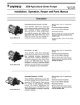
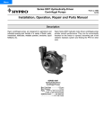
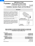
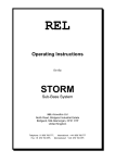
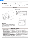
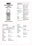
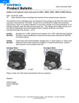
Series 7560
Hydraulically-Driven Roller Pumps
Form L-1488
1/07
Installation, Operation, Repair and Parts Manual
Description
Hypro roller pumps are designed for agricultural and
industrial spraying and transfer of a variety fluids. These
include insecticides, herbicides, emulsives, aromatic
solvents, liquid fertilizers and many other liquids. The
economical rotary-action roller principle requires no check
valves
while
providing
positive
displacement
characteristics with less friction and lower starting torque
than other pumps. Construction features include a Cast
Iron, Ni-Resist or Silver CastTM body, Super Rotor, 416
stainless steel shaft, sealed factory-lubricated ball bearings,
cartridge-type lip seals of Viton or Buna-N, and versatile
Super Rollers. (Super Rollers feature the life of
polypropylene and the chemical resistance of nylon.) The
hydraulically-driven roller pump can be conveniently
mounted anywhere and hooked up to system hydraulics,
eliminating the need for a PTO or a gas engine to drive the
pump.
SERIES 7560
8-ROLLER PUMP
Max. Flow Rate: ..........................................20 gpm
Max. Continuous Pressure: .........................100 psi
Max. Intermittent Pressure: .........................300 psi
Max. Hydraulic Flow: ..................................12 gpm
Max. Hydraulic Pressure: .........................3000 psi
Ports: ..................................3/4" NPT Inlet & Outlet
Hydraulic Ports: ..........7/8"-14 O-ring Inlet & Outlet
General Safety Information
The following attention notices are used to notify and advise
the user of this product of procedures that may be dangerous
to the user or result in damage to the product.
4. Release all pressure within the system before
servicing any component.
Notes are used to notify of installation, operation, or
maintenance information that is important but not safety
related.
6. Secure the outlet lines before starting the pump. An
unsecured line may whip, causing personal injury
and/or property damage.
5. Drain all liquids from the system before servicing
any component. Flush with water.
7. Check hose for weak or worn condition before each
use. Make certain that all connections are tightly
secured.
Caution is used to indicate the presence of a hazard,
which will or can cause minor injury or property damage
if the notice is ignored.
8. Periodically inspect the pump and the system
components. Perform routine maintenance as
required (See Repair Instructions).
Warning denotes that a potential hazard exists and
indicates procedures that must be followed exactly to
either eliminate or reduce the hazard, and to avoid
serious personal injury, or prevent future safety
problems with the product.
9. Use only pipe, hose and fittings rated for the
maximum psi rating of the pump.
10. Do not use these pumps for pumping water or other
liquids for human or animal consumption.
11. Use a pressure relief device on the discharge side of
the pump to prevent damage from pressure buildup
when the pump discharge is blocked or otherwise
closed and the power source is still running.
Danger is used to indicate the presence of a hazard that
will result in sever personal injury, death, or property
damage if the notice is ignored.
12. Never pump acids (i.e. acid fertilizer) with Super
Rollers! When pumping acidic fertilizer, Hypro
recommends only the Silver Series castings and
Teflon rollers, or use one of Hypro's poly centrifugal
pumps.
Do not pump flammable or explosive fluids such as
gasoline, fuel oil, kerosene, etc. Do not use in explosive
atmospheres. The pump should be used only with fluids
that are compatible with the pump component materials.
Failure to follow this notice can result in severe personal
injury, death, and/or property damage and will void the
product warranty.
13. Never run the pump faster than maximum
recommended speed.
14. The sound pressure level of the pump is 82 dBA.
Observe all safety precautions when operating the
pump within close proximity for extended periods by
wearing hearing protectors. Extended exposure to
elevated sound levels will result in permanent loss
of hearing acuteness, tinnitus, tiredness, stress, and
other effects such as loss of balance and
awareness.
1. Do not pump at pressures higher than the maximum
recommended pressure.
2. Maximum liquids temperature is 140° F.
3. Disconnect the power before servicing.
Hazardous Substance Alert
Never use your hand to check the condition of hydraulic
lines or hoses. If hydraulic fluid penetrates the skin, get
medical help immediately. Failure to get proper medical
help may result in loss of limb or life. The safest way to
check hydraulic lines or hoses is by holding a piece of
cardboard next to the hydraulic line or hose.
1. Always drain and flush pump before servicing or
disassembling for any reason.
2. Always drain and flush pumps prior to returning unit
for repair.
3. Never store pumps containing hazardous chemicals.
4. Before returning pump for service/repair, drain out
all liquids and flush unit with neutralizing liquid.
Then, drain the pump. Attach tag or include written
notice certifying that this has been done. It is illegal
to ship or transport any hazardous chemicals
without United States Environmental Protection
Agency Licensing.
The sound pressure level of the pump is 80dBA.
Observe all safety precautions when operating the pump
within close proximity for extended periods of time by
wearing hearing protectors. Extended exposure to
elevated sound levels will result in permanent loss of
hearing acuteness, tinnitus, tiredness, stress and other
effects such as loss of balance and awareness.
2
System Information
NOTE: Use only pipe, fittings, accessories, hose, etc.
rated for the maximum pressure rating of the pump.
1. Select adequate size drive unit to avoid overloading.
Avoid unnecessary restrictions in the line such as
elbows, check valves, and all extraneous curves and
bends.
2. Avoid using looped sections of tubing or pipe which
might permit air to become trapped.
7. Never attach an agitator or any restriction to a
bypass line of a pressure relief device because
system damage may occur.
Figure 1
Typical System
Installation
3. Use pipe joint sealant on pipe threads to assure
watertight connections.
Bypass line
4. Selection of the right type and size of hose is vital to
good performance. Be sure to hook up the lines to the
proper ports on the pump.
5. Always use a good quality suction hose (one or
two braid reinforced hose to prevent collapse) of
at least the same diameter as the inlet port of the
pump. If the suction (inlet) hose is more than four
feet long, then use the next larger size.
6. A strainer should be installed in the suction line. Clean
the strainer as soon as it becomes clogged.
Operation and Maintenance
WARNING: Never pump corrosive or abrasive liquids as
these will cause rapid wear or deterioration of body, rotor,
shaft and seals in the pump. The pump should be used
only with liquids compatible with pump component
materials. Never exceed maximum specified rpm and
pressure. Never run pump dry. Failure to follow this
warning will void the product warranty.
Flush the Pump After Each Use
Priming the Pump
To Prevent Corrosion
To help prime the pump keep the inlet or suction line as
short as possible with a minimum of bends, elbows and
kinks. Make sure all connections are tight and do not leak
air. Make sure line strainer is free of debris. If pump does
not self-prime disconnect suction hose, fill with water and
reconnect to liquid source. Often a squirt of oil into the
ports of the pump will seal clearances and help priming.
Care of the Pump
Hypro roller pumps are all carefully machined to close
tolerance - high pressure operation depends on closefitting parts. Proper care and maintenance will keep your
pump wear at a minimum and will keep it running smoothly
and trouble free for a long time.
3
One of the common causes of faulty pump
performance is “gumming” or corrosion inside the
pump. This prevents the rollers from moving freely in
their rotor slots. Flush the pump with a solution that
will neutralize liquid pumped, mixed according to
manufacturer’s directions.
After cleaning pump as above, flush it with a 50-50 solution
of permanent type automobile antifreeze (containing a rust
inhibitor) and water. A rust inhibitor can also be squirted
into the ports of the pump. Turn shaft several times to draw
protective liquid through pump and coat entire inner
surface. Drain pump and plug ports to keep out air during
storage. For short periods of idleness, noncorrosive liquids
may be left in the pump, but air must be kept out. Plug
ports or seal port connections.
Rotation
Pump rotation must be the same as shown by the arrows
on the pump. Facing the shaft end of the pump, the suction
port is on your right and the shaft must turn clockwise. If
reverse rotation is desired, rotor and shaft assembly must
be reversed so that the shaft extends through the endplate.
See Reversing Rotation section for proper procedure.
Repair Instructions
To Take the Pump Apart
1. Remove the mounting flange and hydraulic motor from
the pump shaft.
2. File off any burrs on the pump shaft.
3. Using a screwdriver, pry off the bearing cover on the End
plate and pump body
4. Remove the end plate bolts.
5. Support the pump at its ports in an end plate support
fixture with the end plate down. Use wood blocks for
Series 1500, 1700 and 4001/4101. Place on press bed.
Center press on pump shaft and apply pressure to press
the pump apart. (See Figure 13).
Figure 15
Figure 16
While the Pump is Apart
Carefully inspect all parts for wear, such as:
• Undersize or swollen rollers, in both length and diameter.
• Worn seals.
• Worn shaft at drive end, and pitted or grooved at the seal area.
• Rough bearings and loss of grease from the bearings.
• Undersize rotor and/or worn roller slots.
Figure 13
• Excessive wear in body – both on inside diameter and at back
face.
• Body cracks at the bolt holes and at the o-ring sealing area.
Figure 14
• End wear (body, end plate, and rotor).
6. With the rollers exposed, remove them – examining
each one carefully for excessive wear. When replacing
damaged rollers, always replace the full set.
• Proper size o-ring in the end plate.
After the above parts have been checked and the various
points have been considered, you may decide if the pump is
repairable. When worn parts have been replaced, always
take up the end clearance by lightly sanding the end plate
and matching body surface (See Figure 17). NOTE: End
clearance should not be more than .004 inches.
7. To remove the rotor with shaft from the end plate –
support the end plate in an end plate support fixture with
the rotor down. Center the bearing disassembly tool or
3/8" bolt on pump shaft. Apply pressure to press shaft
out of ball bearing (See Figure 14).
8. To remove the ball bearing – place the end plate in a end
plate support fixture with the front of the end plate down
(See Figure 15). Center bearing support tool and slowly
press bearing out of casting. Repeat procedure to
remove bearing from pump body (See Figure 16) using
body support fixture.
Inspect Inside of End Plate
If a groove is noticeable, the end plate should be resurfaced
by rubbing it on a sheet of 80-grit emery paper (placed on flat
surface) until all trace of wear has been removed. Rotate the
end plate frequently to remove evenly the same amount of
metal over the entire surface. NOTE: This surface of the end
plate must be perfectly flat. If attempt has been made to
pry pump apart with a screwdriver, file off all nicks, burrs
and other damage marks around the bolt holes.
9. After removing the ball bearing, check the seals in both
end plate and pump body. If wear is evident or leakage
has been noticed, punch the seals out with a screwdriver
and hammer. Seals cannot be removed without
damaging them.
10. To press the shaft out of the rotor, first carefully wash the
rotor and shaft with kerosene – removing all traces of rust
and other foreign matter. Use steel wool or emery cloth,
rinsing parts afterward to wash off all emery dust. Remove
the Allen set screw. Support the rotor in the press through
the slot in the base and press shaft through.
4
Figure 17
Re-Assembly
Do not machine the body casting clean. A more
satisfactory job can be done by hand cleaning with an
emery cloth. Wettable talc powder mixture (5 lbs. powder
to 5 gallons water) may be used for breaking in a
repaired pump, if pump appears to be binding. Run
pump for about 5 minutes. This will also serve to clean
and remove corrosion from the pump. Follow with a
clear rinse, and protect from rust. (See Maintenance.)
Replace Seals and Bearings
Carefully place the seal in the pump body with crimped side
down. Press the seal to the bottom of the cavity, using the
stepped end of the Bearing & Seal Assembly Tool (Figure
18). Then put the bearing in position in the pump body and
press into place with counter bored end of Bearing & Seal
Assembly Tool (Figure 19). Repeat the above procedure
with the end plate. Seat the o-ring in the groove. If
necessary, make sure the o-ring stays in place by stretching
it.
2.
3.
Figure 18
Figure 19
Remove the assembled portion from the arbor press and
invert it on the press table with the Bearing Support Tool under
the bearing. Then place rollers in the roller slots as close to
center of rotor as possible. Place the pump body over rotor
and shaft, and carefully ease the end of the shaft past the lips
of the seal in pump body (Figure 21). Center Bearing Support
Tool with counter bored end down on inner race of ball
bearing, and slowly press the pump body down to fit the end
plate (Figure 22).
Turn pump over; line up bolt holes and replace assembly
bolts. Alternately and evenly tighten the bolts as shown
(Figure 23). NOTE: After bolts have been tightened, check to
see if rotor is centered in pump case. Try to turn the pump
shaft, using a crescent wrench on the shaft as a lever.
Assemble Rotor & Shaft To Endplate
1.
Install the shaft rotor assembly by carefully pushing the short
end of the shaft rotor assembly through the shaft seal into
the end plate. Place in the arbor press with the drive end of
the shaft pointed down. Use the Bearing Support Tool on top
of the bearing and press the assembly together. (Figure 20).
Leave just enough clearance between the rotor and end
plate so that rotor can be turned by hand. If it turns too freely,
sand a little more off the body end that faces the end plate.
You should notice a slight drag, but be able to turn shaft with
an adapter on it by hand. The “slight drag” will wear off after
the pump has been used a short time. Installing new rollers,
seals, bearings and shafts will not prove entirely satisfactory
for volume and pressure unless end clearance is taken up.
Figure 22
Center Rotor in Pump Case
Figure 23
If pump turns hard:
1.
Place short brass rod (or hardwood dowel) against end of
shaft (Figure 24). Center rod on shaft (not on bearing). Tap
lightly with hammer. Try turning rhaft again.
Figure 24
Figure 20
2. If this fails to center the Rotor to where it can be turned
freely — tap other end of shaft, protecting it as above.
When the shaft can be turned by hand — using wrench
as above — it is not binding.
Figure 21
NOTE: If the end plate has been resurfaced, the body
face must also be resurfaced to allow for material taken
off the end plate. Follow same procedure as above with
emery cloth. Before new parts are installed, all burrs
should be removed – particularly in the rotor slots and
body.
5
3. If the pump binds within and tapping does not free it, it
may be necessary to “run the pump in” to wear off high
spots. Use talc solution mentioned earlier. Check pump
frequently during run in.
Troubleshooting
Symptom
Pump does not prime.
Probable Cause(s)
Corrective Action
Obstruction in suction line.
Inspect hose for obstruction such as debris or
loose inner liner.
Leak in suction line.
Suction hose sucked to bottom
or side of tank.
Rollers stuck in pump.
Pump seals leaking air.
Loss of pressure.
Pump turning in wrong direction.
Disassemble pump and inspect rollers.
Replace seals.
Correct rotation of pump (See Reversing Pump).
Check strainer and clean it regularly.
Air leak in inlet side plumbing.
Check hose and connections for leaks.
Use pipe joint sealant and retighten connections.
Kinked or blocked suction hose.
Faulty gauge.
Pump seals leak air.
Inspect suction hose and repair as necessary.
Check relief valve and correct setting or replace
weakened spring.
Replace gauge.
Replace seals.
Nozzle orifices worn.
Hydraulic system overheating.
Cut a notch or “V” in end of suction hose.
Clogged suction strainer.
Relief valve setting too low or
weakened spring.
Pump will not turn.
Check hose and fittings for leaks, and correct.
Replace nozzles.
Pump worn.
Repair pump (See Repair Instructions).
Solid object lodged in pump.
Disassemble pump and remove objects.
Corrosion (rust), scale or residue.
Improper hydraulic motor size.
Insufficient hydraulic hose size.
6
Loosen end plate bolts. Squirt oil into ports to
help free rotor. Retighten bolts.
Refer to Pump Selection Guide to determine
proper size for your hydraulic system.
Check hydraulic hose size. Hose should be at
least 1⁄2" (12.7 mm). For large open-center
systems, 3⁄4" (19.05 mm).
Models 7560C-GM30, 7560N-GM30 and 7560XL-GM30
3
2
20
4
19
18
6
1
8
5
7
10
9
13
17
14
6
15
7
11
12
16
Ref.
Qty.
Part
No. Req'd. Number
Ref.
Description
Qty.
Part
No. Req'd. Number
Description
1
1
1
2
1
1
1
1
0154-7500C
0154-7500N
0154-7500X
0510-7500
Body (Cast Iron)
Body (Ni-Resist)
Body(SilverCast)
Shaft
9
10
11
12
1
1
1
1
1410-0111
1610-0005
0750-7500C
2500-0028
Spacer
Key
Mounting Flange
Hydraulic Motor
4
4
4
5
1
1
1
1
0254-7500C
0254-7500N
0254-7500X
1610-0059
End plate (Cast Iron)
End plate (Ni-Resist)
End plate (SilverCast)
Key
17
18
19
20
20
20
3
1
1
1
1
1
11621
0403-7500P
1720-0014
0308-7560C
0308-7560N
0308-7560X
Bolt
Rotor (Phenolic)
O-ring
Rotor (Cast Iron) with shaft
Rotor (Ni-Resist) with shaft
Rotor (SilverCast) with shaft
3
3
3
3
6
6
7
8
8
8
8
8
2
2
2
1
1005-0004
1002-0004
1052-0004
1055-0004
2112-0003
2112-0001
2008-0001
2300-0020
13
14
15
16
Super Roller (Standard)
Polypropylene Roller (Optional)
Buna-N Roller (Optional)
Teflon Roller (Optional)
Viton Seal (Standard)
Buna-N Seal (Optional)
Seated Ball Bearing
Bearing Cover
Repair Parts Kit No. 3430-0381 Consists of: (8) Ref. 3 Super Rollers,
(1) Ref. 19 O-Ring and (2) Ref. 6 Viton Seals.
Repair Parts Kit No. 3430-0167 Consists of: (8) Ref. 3 Polypropylene
Rollers, (1) Ref. 19 O-Ring and (2) Ref. 6 Viton Seals.
Repair Parts Kit No. 3430-0622 Consists of: (1) Ref. 18 Phenolic
Rotor, (1) Ref. 2 Shaft and (1) Ref. 10 Key.
Flange Kit No. 3430-0636 Consists of: (1) Ref. 11 Mounting Flange, (1)
Ref. 13 Coupler, (1) Ref. 9 Spacer, (3) Ref. 15 Bolt, (2) Ref. 16 Nut, (2)
Ref. 17 Bolt and (1) Ref. 10 Key.
7
1
3
2
2
0524-2500
2210-0004
2210-0063
2250-0082
Coupler
Bolt
Bolt
Nut
Limited Warranty on Hypro Roller Pumps
Hypro warrants to the original purchaser of its products (the “Purchaser”) that such products will be free from defects in material and
workmanship under normal use for the period of one (1) year for all products except: oil crankcase plunger pumps will be free from
defects in material and workmanship under normal use for the period of five (5) years, and accessories will be free from defects in
material and workmanship under normal use for the period of ninety (90) days. In addition, Hypro warrants to the purchaser all forged
brass pump manifolds will be free from defects in material and workmanship under normal use and from damage resulting from environmental conditions for the life of the pump.
“Normal use” does not include use in excess of recommended maximum speeds, pressures, vacuums and temperatures, or use
requiring handling of fluids not compatible with component materials, as noted in Hypro product catalogs, technical literature, and
instructions. This warranty does not cover freight damage, freezing damage, normal wear and tear, or damage caused by misapplication, fault, negligence, alterations, or repair that affects the performance or reliability of the product.
THIS WARRANTY IS EXCLUSIVE. HYPRO MAKES NO OTHER WARRANTY, EXPRESS OR IMPLIED, INCLUDING BUT NOT
LIMITED TO ANY WARRANTY OF MERCHANTABILITY OR FITNESS FOR A PARTICULAR PURPOSE.
Hypro’s obligation under this warranty is, at Hypro’s option, to either repair or replace the product upon return of the entire product to
the Hypro factory in accordance with the return procedures set forth below. THIS IS THE EXCLUSIVE REMEDY FOR ANY BREACH
OF WARRANTY.
IN NO EVENT SHALL HYPRO BE LIABLE FOR ANY INCIDENTAL OR CONSEQUENTIAL DAMAGES OF ANY KIND, WHETHER
FOR BREACH OF ANY WARRANTY, FOR NEGLIGENCE, ON THE BASIS OF STRICT LIABILITY, OR OTHERWISE.
Return Procedures
All pumps or products must be flushed of any chemical (ref. OSHA Section 0910.1200 (d)(e)(f)(g)(h) and hazardous chemicals must be labeled before being shipped* to Hypro for service or warranty consideration. Hypro reserves the right to request
a Material Safety Data sheet from the Purchaser for any pump or product Hypro deems necessary. Hypro reserves the right to “disposition as scrap” pumps or products returned which contain unknown substances, or to charge for any and all costs incurred for chemical testing and proper disposal of components containing unknown substances. Hypro requests this in order to protect the environment and personnel from the hazards of handling unknown substances.
For technical or application assistance, call the Hypro Technical/Application number: 1-800-445-8360.
To obtain service or warranty assistance, call the Hypro Service and Warranty number: 1-800-468-3428;
or call the Hypro Service and Warranty FAX: (651) 766-6618.
Be prepared to give Hypro full details of the problem, including the following information:
1. Model number and the date and from whom you purchased your pump.
2. A brief description of the pump problem, including the following:
• Liquid pumped. State the pH and any non-soluble
• Drive type (gas engine/electric motor; direct/belt drive;
materials, and give the generic or trade name.
tractor PTO) and rpm of pump.
• Temperature of the liquid and ambient environment.
• Viscosity (of oil, or other than water weight liquid).
• Suction lift or vacuum (measured at the pump).
• Elevation from the pump to the discharge point.
• Discharge pressure.
• Size and material of suction and discharge line.
• Type of spray gun, orifice size, unloader/relief valve.
• Size, type, and mesh of the suction strainer.
Hypro may request additional information, and may require a sketch to illustrate the problem.
Contact the factory to receive a return material authorization before sending the product. All pumps returned for warranty work should
be sent shipping charges prepaid to:
HYPRO
Attention: Service Department
375 Fifth Avenue NW
New Brighton, Minnesota 55112
*Carriers, including U.S.P.S., airlines, UPS, ground freight, etc., require specific identification of any hazardous materials being
shipped. Failure to do so may result in a substantial fine and/or prison term. Check with your shipping company for specific instructions.
Printed in USA
2007 Hypro