1
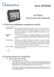
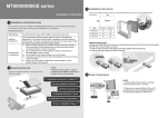
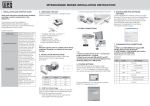
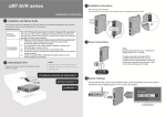
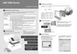
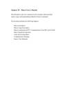
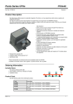
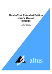
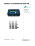
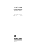
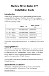
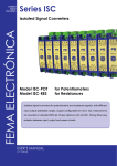
MT6070/8070/6100/8100 i series
3 Installation Instructions
Secure the operator panel in position, using all the fastening holes and the provided brackets
and screws:
(A)
Installation Instruction
Cutout
(B)
1 Installation and Startup Guide
This document covers the installation of MT6000/8000i Series HMI, for the detailed specifications and
operation, please refer to Datasheet and EasyBuilder 8000 User Manual.
Install Environment:
NEMA Rating
Electrical
Environment
Environmental
Considerations
Type
A(mm)
B(mm)
MT6070iH
192
138
MT8070iH
192
138
MT6000/8000i Series HMI is Nema 4X rated.
MT6100i
259
201
The MT6000/8000i Series has been tested to conform to European CE
requirements. This means that the circuitry is designed to resist the effects of
electrical noise. This does not guarantee noise immunity in severe cases. Proper
wire routing and grounding will insure proper operation.
(1) Make sure that the displays are installed correctly and that the operating
limits are followed. .Avoid installing units in environments where severe
mechanical vibration or shocks are present.
(2) Do not operate the unit in areas subject to explosion hazards due to
flammable gases, vapors or dusts.
(3) Do not install the unit where acid gas, such as SO2 exists.
(4) This device should be mounted in the vertical position and for use on the flat
surface enclosure.
(5) Conform to UL508 (ISBN 0-7629-0404-6) machine safety for use in
Pollution Degree 2 Environment.
MT8100i
259
201
2 Unpacking the Unit
Unpack and check the delivery. If damage is found,
notify the supplier.
4 Power Connections
2. Please do not connect HMI with PLC and PC
simultaneously to prevent potential difference
from destroying USB ports of HMI and PC.
To make a connection, strip about 3/8” of
insulation off the end of the wire, turn the
connector screw counterclockwise until the gap
is wide open, insert the wire all the way in, and
turn the screw clockwise until it’s tight.
NOTE:
Place the operator panel on a stable
surface during installation. Dropping it or
letting it fall may cause damage.
(1) Installation Instruction, 2-sided A4 *1
(1)
5 System Settings
When HMI powered up and displays image,
click the system setting button.
(Default System Password: 111111)
It is necessary to connect the HMI to
your network through a RS-45 cable.
(2) MT6000/8000i HMI *1
(2)
(3) Power Connector *1
(3)
(5)
(4)
NOTE:
1. Connect positive DC line to the ‘+24V’
terminal and the DC ground to the ‘0V' terminal.
(4) Brackets & Screws V2.1 *1 pack
(5) Fuse 1.25A/250V 5*20mm *1
( Note 1: For the details of HMI
DIP SW function settings please
refer to Part 8 in this guide. )
Go to the Network tab, you may choose
to auto get DHCP IP, or designate your
own IP.
CAUTION
6 EasyBuilder 8000 Software Settings
Launch EasyBuilder 8000 software, select your
project file, press F7 shortcut key to open
the download dialog box:
Power
Select Ethernet > IP tab > Enter your HMI IP
> Click Download to download this project
file to HMI.
Fusing
Requirements
( Please refer to EasyBuilder 8000 User Manual
for software operation details )
7 Communication Connections
COM1 / COM2 [RS232]
COM1 / COM3 [RS485]
COM3 [RS232]
8 DIP SW Settings
PIN#
High
Voltage
NOTE:
1. COM1 [RS232] RTS/CTS & COM3 [RS232] can’t be used
simultaneously.
2. COM1 [RS485] / COM3 [RS485] with isolation protection.
Symbol
COM1 [RS232]
COM2 [RS232]
1
Not used
2
RxD
Received Data
3
TxD
Transmitted Data
4
TxD
5
GND
6
RxD
7
RTS
Ready to send output
8
CTS
Clear to send input
9
Not used
NOTE: Make sure that all local and national electrical standards are met when
installing the unit. Contact your local authorities to determine which codes apply.
The MT6000/8000i can be powered by DC power only, voltage range: 24±20% Volts DC,
compatible with most controller DC systems. The power conditioning circuitry inside the unit is
accomplished by a switching power supply. The peak starting current can be as high as 2A.
If the display does not come on within 5 seconds of power up, remove power. An internal fuse
will prevent damage if the polarity of the DC power is incorrect. Check wiring for proper
connections and try to power up again.
An Internal fuse will prevent damage for over voltage condition however it isn’t guaranteed. DC
voltage sources should provide proper isolation from main AC power and similar hazards.
A Hard-wired EMERGENCY STOP should be fitted in any system using an MT6000/8000i to
Emergency
comply with ICS Safety Recommendations.
Stop
Supply
Voltage
Condition
Wire
Routing
Transmitted Data
Signal Ground
Received Data
Do not power the MT6000/8000i and inductive DC loads, or input circuitry to the controller, with
the same power supply. Note: The 24 VDC output from some controllers may not have enough
current to power the MT6000/8000i.
a. Wire lengths should be minimized (Max: 500m shielded, 300m unshielded).
b. Wires should be run in pairs with a neutral or common paired with a hot or signal line.
c. If wiring is to be exposed to lightning or surges, use appropriate surge suppression devices.
d. Keep AC, high energy, and rapidly switching DC wiring separate from signal wires.
e. Equip ungrounded DC supplies with a resistor and capacitor in parallel to earth ground.
This provides a path for static and high frequency dissipation. Typical values to use are 1MOhm
and 4700pF.
DANGER
The system designer should be aware that devices in Controller systems could fail and thereby
Hardware
Considerations create an unsafe condition. Furthermore, electrical interference in an operator interface can lead
Com3
[RS485]
Com3
[RS232]
to equipment start-up, which could result in property damage and/or physical injury to the
operator.
If you use any programmable control systems that require an operator, be aware that this
potential safety hazard exists and take appropriate precautions. Although the specific design
steps depend on your particular application, the following precautions generally apply to
installation of solid-state programmable control devices, and conform to the guidelines for
installation of Controllers recommended in NEMA ICS 3-304 Control Standards.
Symbol
Com1
[RS485]2w
Com1
[RS485]4w
1
Rx-
Data-
Rx-
2
Rx+
Data+
Rx+
3
Tx-
Tx-
4
Tx+
Tx+
5
GND
Signal Ground
6
Data-
Data-
7
TxD
Transmit
checks built into the program, with an out-of-limit safe shut down procedure to ensure safety of
personnel.
8
RXD
Receive
GME680700_MT6/8070iH2/iH3_MT6/8100iV2_Installation_120509
9
Data+
SW1
SW2
SW3
SW4
ON
OFF
OFF
ON
Touch Screen Calibration Mode
OFF
ON
OFF
ON
Hide HMI System Setting Bar
OFF
OFF
ON
ON
Boot Loader Mode
OFF
OFF
OFF
ON
Normal
OFF
OFF
OFF
OFF
Not supported
PIN#
To conform with ICS Safety Recommendations, checks should be placed in the controller to
Programming
ensure that all writable registers that control critical parts of plant or machinery have limit
Considerations
Data+
Mode
Limited Warranty
This product is limited warranted against defects in design and manufacture. The proven
defective product will either be repaired or replaced, at Weintek’s discretion. This warranty
shall not cover any product which is
(a) Out of warranty period which is 1 year from the date of purchase.
(b) Damage caused by Force Majeure, accident, negligence, improper installation or misuse.
(c) Product has been repaired or taken apart by unauthorized technicians.
(d) Products whose identification markings have been removed or damaged.