1
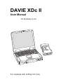
DAVIE XDc II
User Manual
for Runtime 5.4.2
For Laptops with softing VCI only
DAVIE XDc II
Contents
CONTENTS
1
Safety Notices...................................................................................................... 1-1
1.1
Important safety notices..................................................................................................... 1-2
2
General Information ............................................................................................ 2-1
2.1
2.2
2.3
2.4
2.5
2.6
2.6.1
2.6.2
General Notes.................................................................................................................... 2-1
Safety Instructions ............................................................................................................. 2-1
Designated Use ................................................................................................................. 2-2
Associated Documents ...................................................................................................... 2-2
EC Declaration of Conformity ............................................................................................ 2-3
Technical Data ................................................................................................................... 2-4
Laptop................................................................................................................................ 2-4
Vehicle Communication Interface (VCI)............................................................................. 2-4
3
Components......................................................................................................... 3-1
3.1
3.2
3.3
3.4
3.4.1
3.4.2
3.4.2.1
3.4.2.2
3.4.3
Overview............................................................................................................................ 3-1
DAVIE XDc II Laptop ......................................................................................................... 3-1
DAVIE XDc II Software ...................................................................................................... 3-2
Vehicle Communication Interface (VCI)............................................................................. 3-2
Led Status.......................................................................................................................... 3-4
VCI Battery ........................................................................................................................ 3-5
Buffering ............................................................................................................................ 3-5
Charging ............................................................................................................................ 3-5
RADIO RF exposure.......................................................................................................... 3-6
4
Operation.............................................................................................................. 4-1
4.1
4.2
4.3
4.4
4.5
4.6
4.7
4.8
Power-up ........................................................................................................................... 4-1
Start-up and Exit ................................................................................................................ 4-1
Administrator Login on a newly delivered or installed DAVIE XDc II ................................. 4-1
User Login ......................................................................................................................... 4-8
Touchscreen (optional) ...................................................................................................... 4-9
Use of the Screens ............................................................................................................ 4-10
Logout................................................................................................................................ 4-12
How to switch wired or wireless communication................................................................ 4-13
5
Vehicle Identification........................................................................................... 5-1
5.1
5.2
5.3
5.4
Start of Diagnostic Session................................................................................................ 5-1
Automatic Identification...................................................................................................... 5-2
Manual Identification.......................................................................................................... 5-4
Deselect ECU Installation Variant...................................................................................... 5-7
6
Direct Testing....................................................................................................... 6-1
6.1
6.2
6.3
6.4
6.5
6.5.1
6.5.2
6.5.3
Overview............................................................................................................................ 6-1
Vehicle Identification.......................................................................................................... 6-2
Executing test procedures ................................................................................................. 6-4
Navigation bar.................................................................................................................... 6-6
Go To button...................................................................................................................... 6-7
EXIT ................................................................................................................................... 6-8
Health Check ..................................................................................................................... 6-8
Fault Memory Contents ..................................................................................................... 6-8
©
200845
1
DAVIE XDc II
Contents
6.5.4
6.5.5
6.5.6
6.5.7
6.6
6.6.1
6.6.2
Documents ......................................................................................................................... 6-9
Test Plan ............................................................................................................................ 6-10
ECU Installation Variants ................................................................................................... 6-11
Direct Test Selection Screen..............................................................................................6-11
Use of illustrations .............................................................................................................. 6-11
Index page.......................................................................................................................... 6-12
Explanation of buttons on the screen ................................................................................. 6-13
7
Guided Diagnosis ................................................................................................7-1
7.1
7.2
7.3
7.4
7.5
7.5.1
7.6
7.7
7.7.1
7.7.2
7.7.3
7.7.4
7.7.4.1
7.7.4.2
7.7.4.3
7.7.5
7.8
7.8.1
7.8.2
7.8.3
7.9
Principle op of Guided Diagnosis ....................................................................................... 7-1
Starting Guided Diagnosis.................................................................................................. 7-2
Vehicle Identification .......................................................................................................... 7-2
Guided Entry ...................................................................................................................... 7-3
Guided entry with Fault code(s) ......................................................................................... 7-3
Health Check...................................................................................................................... 7-4
Guided entry with a Symptom ............................................................................................ 7-5
Test plan............................................................................................................................. 7-7
Test plan Overview............................................................................................................. 7-7
Building a Test plan based on Fault codes and Symptoms ............................................... 7-8
Test plan screen lay out ..................................................................................................... 7-9
Executing tests ................................................................................................................... 7-10
Direct test ........................................................................................................................... 7-11
Symptom test or Check test ............................................................................................... 7-11
Measurement Test ............................................................................................................. 7-12
Function Component selection........................................................................................... 7-13
Extra options ...................................................................................................................... 7-15
Fault Memory Contents ...................................................................................................... 7-15
Deselecting Systems.......................................................................................................... 7-16
Suspend session ................................................................................................................ 7-17
Quitting Guided Diagnosis.................................................................................................. 7-21
8
Administration .....................................................................................................8-1
8.1
8.2
8.3
8.4
8.4.1
8.4.2
8.4.3
8.4.4
8.4.5
8.4.6
8.5
8.6
8.7
8.8
8.9
8.10
8.11
8.12
8.13
Overview ............................................................................................................................ 8-1
Start Administration ............................................................................................................ 8-1
Select Function................................................................................................................... 8-3
Install update ...................................................................................................................... 8-4
Install update of a new Runtime CD:.................................................................................. 8-4
Install update of a new delivered Application CD: .............................................................. 8-4
Install a second language................................................................................................... 8-6
Install update of a new Parts Rapido Subset CD ............................................................... 8-7
Install update(s) from DAVIE XDc Download. .................................................................... 8-7
Install update from Parts Rapido online ............................................................................. 8-8
Change language ............................................................................................................... 8-8
Dealership identifier............................................................................................................ 8-9
Initial Graphic ..................................................................................................................... 8-9
Version information ............................................................................................................ 8-10
Contents of application data............................................................................................... 8-11
Passwords.......................................................................................................................... 8-11
Log Files............................................................................................................................. 8-12
Helpdesk Log Files............................................................................................................. 8-14
Vehicle test Files ................................................................................................................ 8-14
2
©
200845
DAVIE XDc II
Contents
9
VCI Configuration Manager ................................................................................ 9-1
9.1
9.2
9.2.1
9.2.2
9.2.3
9.3
9.3.1
9.3.2
9.3.3
9.3.4
VCI Tray Icon..................................................................................................................... 9-1
The WLAN Quality Indicator .............................................................................................. 9-3
General .............................................................................................................................. 9-3
Interface ............................................................................................................................. 9-3
Rating of the WLAN connection quality indicator............................................................... 9-4
Start up the VCI Configuration Manager Program ............................................................. 9-5
Status info.......................................................................................................................... 9-6
Basic Setup........................................................................................................................ 9-8
Advanced Setup ................................................................................................................ 9-9
Common Settings .............................................................................................................. 9-12
10
Help....................................................................................................................... 10-1
10.1
10.2
10.3
10.4
10.5
Overview............................................................................................................................ 10-1
Start Help........................................................................................................................... 10-1
Help Overview ................................................................................................................... 10-2
Help on Topics ................................................................................................................... 10-3
Help on the selected button ............................................................................................... 10-4
11
Troubleshooting .................................................................................................. 11-1
11.1
11.2
11.2.1
11.2.2
11.2.3
11.3
11.3.1
11.3.2
11.3.3
11.4
11.4.1
11.4.2
11.4.3
11.5
Classification...................................................................................................................... 11-1
Computer Hardware .......................................................................................................... 11-2
Laptop self test .................................................................................................................. 11-2
Laptop does not work correctly.......................................................................................... 11-2
Touchscreen (optional) ...................................................................................................... 11-3
Software installation........................................................................................................... 11-3
Windows Explorer popup ................................................................................................... 11-3
CD incompatible with Base-CD ......................................................................................... 11-4
Problems with application data .......................................................................................... 11-4
Problems with Vehicle Communication Interface (VCI) ..................................................... 11-5
Self-test of the VCI Configuration Manager. ...................................................................... 11-5
VCI Configuration Manager Self-test error list ................................................................... 11-6
Wireless Communication recovery .................................................................................... 11-8
Fault Report to Local helpdesk .......................................................................................... 11-9
12
Care and Maintenance ........................................................................................ 12-1
12.1
12.2
12.2.1
12.2.2
12.3
12.3.1
12.3.2
12.3.3
Visual check of the DAVIE XDc II components ................................................................. 12-1
Cleaning the components .................................................................................................. 12-1
Cleaning the laptop ............................................................................................................ 12-1
Cleaning the VCI................................................................................................................ 12-1
Batteries............................................................................................................................. 12-2
Laptop battery.................................................................................................................... 12-2
VCI battery......................................................................................................................... 12-2
Replace the VCI battery..................................................................................................... 12-2
©
200845
3
DAVIE XDc II
Contents
4
©
200845
© 200845 DAF Trucks N.V., Eindhoven,
the Netherlands
In the interest of continuing product
development, DAF reserves the right to
change specification or equipment at any time
without notice.
No part of this publication may be reproduced
and/or published by printing, photocopying,
microfilming or by any other means without
the manufacturer's prior permission in writing.
©
200845
DW132966
DAVIE XDc II
Safety Notices
1
SAFETY NOTICES
Severe injury or damage may result if unqualified persons attempt to work on
the equipment or if the safety notices are disregarded.
The safety notices in this operating manual and on the products have the
following meanings:
DANGER
Indicates an imminently hazardous situation, which, if not avoided, will result in
death or serious injury.
WARNING
Indicates a potentially hazardous situation, which, if not avoided, could result in
death or serious injury.
CAUTION
Used with the safety alert symbol, this indicates a potentially hazardous
situation, which, if not avoided, may result in minor or moderate injury.
CAUTION
Used without the safety alert symbol, this indicates a potentially hazardous
situation, which, if not avoided, may result in property damage.
NOTICE
Used without the safety alert symbol, this indicates a potential situation, which,
if not avoided, may result in an undesirable result or state.
NOTE
This is important information about the product or how it is used, or indicates a
part of the documentation requiring particular attention.
©
200845
1-1
DAVIE XDc II
Safety Notices
General safety notices are listed below. Additional safety notices are given
throughout the operating manual where they are relevant.
1.1
Important safety notices
Read all the safety notices:
WARNING
Please read the operating and safety instructions which are delivered with the
laptop.
WARNING
If the power cable or DAVIE XDc II is damaged, you must not use the DAVIE
XDc II until a qualified specialist has tested and, if necessary, repaired the
equipment.
WARNING
The power cable must not be laid over tables, benches or cabinets. It must not
be located near hot objects or rotating parts.
WARNING
The length of the power cable must not be extended. Use only the supplied
power cable as far as possible.
WARNING
The DAVIE XDc II must not be operated in the vicinity of open fuel containers
or other open containers with inflammable substances due to the risk of
explosion or fire.
WARNING
Make sure there is adequate ventilation when you are working on vehicles with
running motors to prevent the risk of carbon monoxide poisoning.
1-2
©
200845
DAVIE XDc II
Safety Notices
WARNING
Use the DAVIE XDc II only as described in the operating manual. Use only the
manufacturer's recommended attachments.
WARNING
The DAVIE XDc II is a safety class 1 device and is equipped with a safety tested
power cable. It may only be connected to systems with equipment grounding
conductors (TN systems) and grounding sockets.
WARNING
Ensure the DAVIE XDc II is secured during test drives and connect it to the
vehicle using the DAVIE XDc II Interface. A second person must operate the
DAVIE XDc II.
WARNING
If you open the equipment without authorization or carry out improper repairs,
you may place yourself in serious danger.
WARNING
To reduce the risk of electric shock, do not use on wet surfaces or expose to
rain.
NOTE
Fluctuations and deviations of the mains voltage beyond the permissible
tolerance may lead to electronics failures.
KEEP THESE SAFETY NOTICES IN A SAFE PLACE
©
200845
1-3
DAVIE XDc II
Safety Notices
1-4
©
200845
DAVIE XDc II
General Information
2
GENERAL INFORMATION
2.1
General Notes
This operating manual contains the necessary information for the proper use of
the "DAF Vehicle Investigation Equipment - Excellence in Diagnosis compact",
known as DAVIE XDc II.
Please refer the DAVIE XD user manual for DAVIE XD and or yellow VCI
specific issues.
This manual is intended for technically qualified personnel with knowledge in
the area of vehicle diagnostics and testing and basic knowledge of Windows
XP.
Knowledge and technically flawless implementation of the safety instructions
and warnings contained in this operating manual are essential for the safe
installation, operation and maintenance of the DAVIE XDc II package.
For reasons of clarity, this operating manual does not contain all the details of
all uses of the operating modes described, and cannot cover every conceivable
case relating to installation, use, servicing and maintenance.
Likewise, the contents of the dialog screens shown here may differ slightly from
those displayed on the screen depending on the version.
2.2
Safety Instructions
Pay attention to the safety instructions for the DAVIE XDc II. They are listed
after the table of contents.
©
200845
2-1
DAVIE XDc II
General Information
2.3
Designated Use
DAVIE XDc II may be used for:
•
Vehicle diagnosis
•
Inform Service Rapido 2.0 and Parts Rapido 2.2
NOTE
DAF has not tested other NON-DAF released applications on the DAVIE XDc II.
DAF can not guaranty when other applications have been installed on the
DAVIE XDc II, that the DAVIE XDc II application runs free from problems.
The described product was developed, manufactured, tested and documented
in accordance with safety standards. Consequently, if the safety instructions,
the specified commissioning procedure, the rules governing designated use
and the service and maintenance recommendations are followed there is, under
normal circumstances, no danger that the DAVIE XDc II will present any risk to
property or health and safety.
2.4
Associated Documents
In addition to this operating manual, which is intended for use in the workshop,
the following relevant technical documents also apply to the DAVIE XDc II:
2-2
•
Quickstart Vehicle Communication Interface
•
Diagnostic Manual
•
Installation Manual
•
Application Information
©
200845
DAVIE XDc II
General Information
2.5
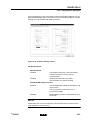
©
EC Declaration of Conformity
200845
2-3
DAVIE XDc II
General Information
2.6
Technical Data
2.6.1
Laptop
See originally delivered documentation which is delivered with the laptop.
2.6.2
Vehicle Communication Interface (VCI)
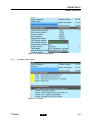
Dimensions (W x D x H)
126 x 214 x47 mm
Weight
1.1 kg
Ambient conditions
Operation
Ambient temperature 0 to +50 °C
Relative humidity
10 to 90 %,
at max. +25 °C
non-condensing
Storage
Ambient temperature -20 to +80 °C
Relative humidity
<90% non-condensing)
Temperature gradient
5 °C/1 h
Power supply from the vehicle
electrical system
The VCI must be powered from the vehicle.
Rated voltages
8 to 32 V DC
Current consumption in the
load range
Max. 1 A
Power supply from the
rechargeable battery
If external power is interrupted, the VCI will be
buffered by the rechargeable battery
Battery type
NiMH 4,8V/1100mAh
Buffered time
Between 20 and 60 sec or no buffering
Communication
2-4
USB
For communication by wire to the DAVIE XDc II
Wireless LAN
For wireless communication to the DAVIE XDc II
via a (internal) wireless network card according
802.11b and 802.11g
©
200845
DAVIE XDc II
General Information
WLAN module VCI
Used WLAN-Module:
Frequency Range:
WiPort from Lantronix Inc.
Type of Transmission:
802.11b/g = 2400 – 2483.5 MHz
Transfer Rate:
Direct Sequence Spread Spectrum
Number of Channels:
1/5.5/11 Mbps for 802.11b mode
6/36/54 Mbps for 802.11g mode
Modulation Type:
802.11b mode (2400-2483.5 MHz) = 11
802.11g mode (2400-2483.5 MHz) = 11
Transmit Output Power:
CCK, OFDM
Ch. 1-11 14dBm Average (Typical)
for 802.11b mode
Ch. 1-10: 14dBm Average &
Ch. 11: 12dBm Average(Typical)
for 802.11g mode
©
200845
2-5
DAVIE XDc II
General Information
2-6
©
200845
DAVIE XDc II
Components
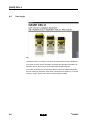
3
COMPONENTS
3.1
Overview
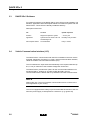
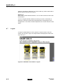
DAVIE XDc II system features;
•
Portable equipment DAVIE XDc II Laptop with an optional touchscreen and
installed with the DAVIE XDc II software packages: Runtime, Application
and Parts Rapido Subset.
•
USB or wireless communication with the diagnostics interface in the vehicle
via the DAVIE XDc II Vehicle Communication Interface (VCI).
•
VCI Configuration Manager program to set-up the wireless communication
between the DAVIE XDc II and the DAVIE XDc II Vehicle Communication
Interface (VCI).
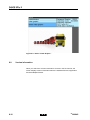
Figure 3-1 DAVIE XDc II Panasonic CF-19 with VCI
3.2
DAVIE XDc II Laptop
See originally documentation which is delivered with the laptop.
©
200845
3-1
DAVIE XDc II
Components
3.3
DAVIE XDc II Software
For optimal functioning of the DAVIE XDc II, three CD's must be installed. The
Runtime, Application and Parts Rapido Subset are needed to operate with the
DAVIE XDc II. These CD's are already installed at delivery.
Description of the CD's
3.4
CD
Content
Update sequence
Runtime
Diagnostic Operation system
~ once a year
Application
System tests for Direct Test and
Guided Diagnosis
Normally every 8 weeks
Parts Rapido Subset
Truck database
Every 4 weeks
Vehicle Communication Interface (VCI)
The DAVIE XDc II communicates with the ECU's installed in the truck via the
truckside "Diagnostic Connector" by using a special communication interface,
called the Vehicle Communication Interface (VCI).
The VCI switches the input channel automatically to the required data line (Kline, L-line) or CAN-bus of the truckside "Diagnostic Connector".
The DAVIE XDc II provides two options for the communication between VCI
and DAVIE XDc II, wireless or via cable (USB). Normally, the VCI
communicates with the DAVIE XDc II by Wireless-LAN radio communication.
NOTE
Please take care. The use of wireless communication has to conform to the
local regulations of your country.
The VCI is equipped with a battery to prevent immediate shut down of the VCI
when the power supply is interrupted for a short time. (e.g. ignition off)
3-2
©
200845
DAVIE XDc II
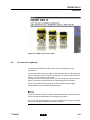
Components
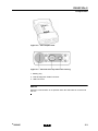
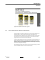
Figure 3-2 VCI Complete view
Figure 3-3 VCI View of the top side of the housing
1. Battery plug
2. Vehicle Diagnostic Cable Connector
3. USB-Connector
NOTE
Wireless communication is not possible when the USB cable is connected to
the VCI.
©
200845
3-3
DAVIE XDc II
Components
3.4.1
Led Status
Figure 3-4 VCI Front view LED
Yellow LED: DAVIE XDc Communication
On:
Communication with DAVIE
Slow flashing:
WLAN-Mode changing Adhoc <--> Infrastructure
Off
No communication with DAVIE
Blink Code:
Internal error 1*
Blue LED: Vehicle communication
On:
Communication with vehicle
Off:
No vehicle communication
Green LED: VCI Internal status
On:
Firmware is running
Slow flashing:
Update
Fast flashing:
Over temperature
Off
VCI off or internal error
Red LED: Battery status
3-4
On:
Battery malfunction
Slow flashing:
Not ready for buffering or last 10 seconds of
buffering
Fast flashing:
Over temperature, no charging possible
Off:
No battery or battery ready
©
200845
DAVIE XDc II
Components
NOTE
Temperature monitoring is implemented in the VCI. This protects the VCI
against damage from overheating.
When a critical temperature is reached, the user is warned by a fast flashing red
LED. If the user does not react and the temperature rises over the limit value,
the VCI is switched off.
The VCI has to cool down for approximately 10 minutes before it can be
reactivated.
3.4.2
VCI Battery
3.4.2.1
Buffering
To prevent immediate shutdown of the VCI during periods in which the vehicle's
power supply is switched off (e.g. in order to reset electronic control units in the
vehicle), the VCI is capable of buffering itself for a brief period between 20 and
60 seconds.
The last 10 seconds of buffering are indicated by slow flashing of the red LED.
With the VCI Configuration Manager the buffer settings can be changed
between 20 and 60 seconds or turned off.
3.4.2.2
Charging
The battery will be charged each time the VCI is connected to the vehicle and
the vehicle's power supply. After power-up, the battery is charged for 5 minutes
with a high current. After this time period, charging switches to a mode with low
current.
The battery indicator flashes if the buffer function is not possible. The VCI shuts
down immediately whenever the power supply is disconnected.
In case of long storage periods a deep discharge of the battery is possible. In
this case a minimum charging time of 20 minutes is necessary to bring up the
batteries to their normal use range and to permit the VCI buffering for one cycle.
Overcharge of the batteries will be avoided.
NOTE
Over temperature protection of the batteries is monitored by a temperature
sensor.
©
200845
3-5
DAVIE XDc II
Components
3.4.3
RADIO RF exposure
This device complies with the FCC RF (radio frequency) Exposure
Requirements set forth for an uncontrolled/general population environment. A
separation distance of 20 cm between the transmitting antenna and the human
body must be assured during normal operating conditions.
The Part 15 radio device operates on a non-interference basis with other
devices operation at this frequency when integrated antennas. Any changes or
modification to the product not expressly approved by the manufacturer could
void the user's authority to operate this device.
This device complies with part 15 of the FCC Rules. Operation is subject to the
following two conditions:
1. This device may not cause harmful interference, and
2. this device must accept any interference received, including interference
that may cause undesired operation.
3-6
©
200845
DAVIE XDc II
Operation
4
OPERATION
4.1
Power-up
See, for start-up of the DAVIE XDc II laptop, the originally delivered laptop
documentation.
4.2
Start-up and Exit
To start the DAVIE XDc II software, double click on the DAVIE XDc II Icon on
the desktop or by the shortcut in the Windows Start menu.
Figure 4-1 DAVIE XDc II Icon
To close the DAVIE XDc II software, use the cross in the upper right corner.
4.3
Administrator Login on a newly delivered or installed DAVIE XDc II
At the first start up after installation of DAVIE XDc II Runtime CD, you must
enter your dealership code to access the DAVIE XDc II operating modes. Later
changes or deletions of an entered dealership code cannot be made in the
workshop.
When the DAVIE XDc II is started for the first time the Login button at the right
hand margin of the screen and the version information of the Runtime,
Application and Parts Rapido Subset is displayed in the upper parts of the
screen.
NOTE
The Application and parts Rapido Subset version information is not displayed
after a complete new Runtime installation.
First install the latest Application and Parts Rapido Subset version when you
enter the administrator menu.
©
200845
4-1
DAVIE XDc II
Operation
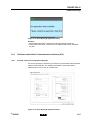
Figure 4-2 Start screen before Login
To start up the DAVIE XDc II, the DAVIE XDc II Administrator must proceed
as follows:
1. Press the "Login" button (see Figure 4-2).
2. The screen in Figure 4-3 is displayed. Under "User ID", enter "ADMIN" and
press the "Return button" on the keyboard.
3. Under "Password", enter password "DAF". Press the "Return button" on the
keyboard.
Figure 4-3 "Login" screen: entering the password
4-2
©
200845
DAVIE XDc II
Operation
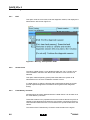
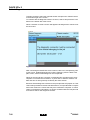
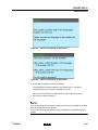
4. Then enter an Administrator password of your choice.
5. After entering the password, press the "Return button" again. A display is
prompted to insert the dealership code USB-stick containing the personal
dealership code for this DAVIE XDc II laptop. Press "OK" to continue.
Figure 4-4 "Insert dealership code"
6. DAVIE XDc II will terminate the function and return to the start screen.
The label of the "Login" button has changed to "Logout" and a new button
"Administration" is displayed.
©
200845
4-3
DAVIE XDc II
Operation
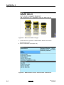
Figure 4-5 Start screen after 1st login
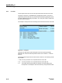
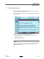
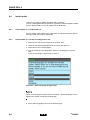
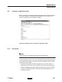
7. In the start screen, press the "Administration" button to access the
administration menu.
8. Select "Passwords" (see Figure 4-6).
Figure 4-6 Administration screen: select function "Passwords"
4-4
©
200845
DAVIE XDc II
Operation
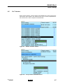
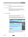
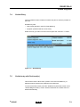
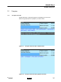
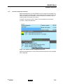
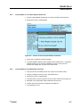
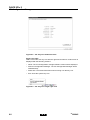
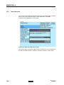
9. In the "Passwords" screen, users of the DAVIE XDc II system and
passwords can be add and changed (see Figure 4-7). All entered users are
displayed with their user levels and hidden passwords.
•
To edit an entry, select the relevant element in the "User ID" column. A
dialog box opens in which you can edit the user level of the selected
user.
•
To add an additional user, select an empty element in the "User ID"
column.
•
To enter or change passwords, select the corresponding element in the
"Password" column.
Figure 4-7 Administration screen: user set-up
NOTE
Depending on the different user levels "Senior Technician" and "Master
Technician" only those test procedures to which the specific technician level
has access to will be displayed by the DAVIE XDc II and implemented by the
technician.
The Senior Technician can only readout in- and outputs and diagnose. The
Master Technician has also the rights to program the ECU's.
Only the Administrator has rights to add users and to set the Passwords.
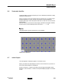
If a column is selected, a virtual keyboard appears and a new user can be typed
in or a selected one can be changed.
©
200845
4-5
DAVIE XDc II
Operation
Figure 4-8 Keyboard
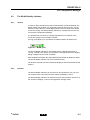
10.Enter the User Level of "Senior Technician" or "Master Technician" and
usernames including the passwords.
11. When all required users are entered, exit the function by pressing the
"Back / <" button to return to the "Administration" screen.
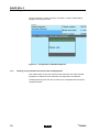
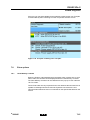
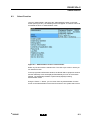
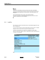
12.In the "Administration" screen, select "Dealership Identifier".
Figure 4-9 Administration screen, select function "Dealership Identifier"
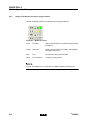
13.If selected the function, a keyboard will be displayed and type in a new
"Dealership Identifier" or change it.
Use the "SH" button of the keyboard to switch between upper and lower
case letters.
Press the "Back / <" button to return to the "Administration" screen.
4-6
©
200845
DAVIE XDc II
Operation
Figure 4-10 Keyboard: Dealership Identifier
14.The final basic setting, which could be implemented before starting to work
with the DAVIE XDc II, is to change the "Initial graphic", the displayed
graphic in the start screen.
Use the "Forward / >" button to go step by step through all available "Initial
Graphics".
Use the "Back / <"button to accept the displayed graphic in the start screen
and to return to the "Administration" screen.
15.Return to the start screen and logout as Administrator.
16.It may be necessary to set a unique VCI-ID if more than 1 pair of DAVIE
XDc II and VCI is used in the same workshop (refer to "Configuration
manager").
©
200845
4-7
DAVIE XDc II
Operation
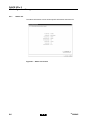
4.4
User Login
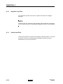
Figure 4-11 Start screen: Administrator Login
The DAVIE XDc II is ready for use when the system start screen is displayed.
The "Help" function can be selected in all modes and provides information on
operation and on the functions of the individual navigation buttons.
To access the buttons for the functions "Direct Test" and "Guided Diagnosis",
the user must login with their "User name" and personal "Password". To do this,
press the "Login" button and enter the required personal data.
4-8
©
200845
DAVIE XDc II
Operation
Figure 4-12 Start screen: User Login
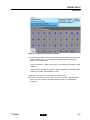
4.5
Touchscreen (optional)
The entire touch-sensitive surface of the screen is designated as the
touchscreen.
The screen senses touch by a finger or delivered touch pen, thereby replacing
the conventional function of a mouse or keyboard. To select an element (text or
button), you must touch it on the screen.
As long as you are touching the screen, you can change the current selection.
When you stop touching the screen, the selected element is activated.
See for more features and settings of the touchscreen also the original
documentation which is delivered with the laptop.
NOTE
The screen reacts to all touch. When using the DAVIE XDc II, make sure it can
not be touched unintentionally by any equipment or people.
Do not use any other objects than your finger or delivered touch pen to operate
the screen. Using other objects can result in damage.
©
200845
4-9
DAVIE XDc II
Operation
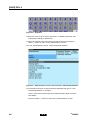
4.6
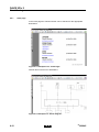
Use of the Screens
The graphical screens display all information and control functions.
The screens shown all the same structure: the lower portion contains a bar with
operating elements (the navigation bar), the middle and largest portion contains
the work window in which you make your selection or enter values. The
information windows are above the work window.
NOTE
If the DAVIE XDc II is not used for a time, the screensaver could be activated.
This is a Windows XP setting. As soon as you press the screen near the upper
left edge (so as not to unintentionally launch any screen functions), the screen
activated last is displayed.
Figure 4-13 Overview: Screens
1. Navigation bar
2. Work window
3. Information windows
4. Selection bar
5. Pointer
6. Button on the navigation bar
4-10
©
200845
DAVIE XDc II
Operation
Navigation bar (1)
The navigation bar is in the lower portion of the screen. You can call up help and
service functions with the buttons in this bar.
There are up to five different buttons available on the navigation bar. The
number of buttons depends on the screen and the current status. Press the
button to execute the desired command. You can recognize whether a button
is active by its colour. If the button is darkened, it has been pressed and
activated.
Button "Go to"
The navigation bar includes the "Go to" button, with which you can:
•
Exit the diagnostic session
•
Jump across several different screens to a specified destination screen
Work window (2)
The work window is the largest portion of the screen. The display changes
depending on the operating mode.
Information window (3)
Most screens contain two information windows above the work window. These
windows are only for displaying information; they do not control any operations.
•
The left window displays the name of the operating mode: Direct Testing),
the name of the displayed subfunction (here: Function/ Component
Selection) user instructions (here: Select function or component) or status
display.
•
The right window displays the device number and workshop identifier,
terms that you have previously selected or selected function.
Selection bar (4)
When you select a line within the work window, your selection is highlighted by
a black selection bar. The text portion you select is inverted. It is possible to
scroll between the displayed lines while constantly pressing the screen or
mouse button. If the list is larger than the screen, a scroll bar will appear on the
right-hand side.
In most cases, the next screen is activated as soon as you stop pressing the
screen or mouse button after you have marked a text.
In some screens, there is only a single selection of lines possible so, if you
select one line, a previously selected line will be automatically deselected.
Otherwise, the DAVIE XDc II offers you the option of selecting or deselecting
multiple options. Select or deselect all the options you want and confirm it by
pressing the "Forward / >" button.
Pointer (5)
The pointer takes on various shapes depending on its current function.
©
200845
•
With the arrow you can select functions or buttons.
•
The hourglass appears when the DAVI XDc Laptop is processing your
entries.
4-11
DAVIE XDc II
Operation
While the hourglass is displayed, you cannot make any entries. Wait until the
pointer returns to the form of an arrow.
Buttons (6)
Each screen contains different buttons. You can select various functions with
these buttons.
You can recognize whether a button is active by its colour. If the button is
darkened, it has been pressed and activated buttons are displayed on the
navigation bar. The number of buttons depends on the screen and the current
status.
4.7
Logout
To logout an Administrator or User, press the "Logout" button in the start
screen, then only the "Login" and "Help" buttons are displayed. Another user
may now log in.
Figure 4-14 Standard screen before "Logout"
4-12
©
200845
DAVIE XDc II
Operation
Figure 4-15 Standard screen after "Logout"
4.8
How to switch wired or wireless communication
The DAVIE XDc II provides two options for the communication between VCI
and DAVIE XDc II, radio and USB communication. Normally the VCI
communicates with the DAVIE XDc II by Wireless-LAN radio communication.
The safest way to change the communication is to close the DAVIE XDc II
program and connect or disconnect the USB-cable.
In order to detect interferences of the communication via WLAN between the
DAVIE laptop and the Blue VCI, the quality of the WLAN connection can be
observed. This is done by a small display which shows a rating of the WLAN
connection quality. The WLAN Quality Indicator is controlled by the VCI Tray
Icon and the Configuration Manager.
After installation and when the USB-cable is disconnected the display is visible.
The WLAN Quality Indicator can be moved and closed.
©
200845
4-13
DAVIE XDc II
Operation
4-14
©
200845
DAVIE XDc II
Vehicle Identification
5
VEHICLE IDENTIFICATION
The DAVIE XDc II has two options for identifying a vehicle and the used
systems.
•
Automatic vehicle identification
•
Manual vehicle identification
The automatic vehicle identification from the truck chassis number and the
"Parts Rapido Subset" database is usually used. This ensures that the
assignment of the test procedures corresponds to the vehicle configuration.
If automatic identification from the truck chassis number is not possible, manual
identification can be carried out.
NOTE
The complete vehicle configuration is saved in the log file.
5.1
Start of Diagnostic Session
If a diagnostic Session is started (Direct Test or Guided Giagnosis),
DAVIE XDc II checks the communication to the Vehicle Communication
Interface. After the communication check, the vehicle identification will be
started.
When the communication is unsuccessful the DAVIE XDc II displays a
message.
Figure 5-1 Communication verification message
©
200845
5-1
DAVIE XDc II
Vehicle Identification
• OK
This option instructs DAVIE XDc II to ignore the inability to establish
communication and display the Vehicle Identification screen.
DAVIE XDc II now displays the Vehicle Identification screen and waits for the
user to enter the "Chassis" number. There is still no communication between
the DAVIE XDc II and VCI.
• Repeat
This option instructs DAVIE XDc II to repeat the attempt to establish
communications. If successful, the system will display the Vehicle Identification
screen.
• Exit
This option instructs DAVIE XDc II to cancel "Diagnostic Session" and to return
to the "Start Screen".
All options other than "OK", Repeat" and "Exit" are locked and unavailable to
the user.
5.2
Automatic Identification
Automatic vehicle identification can be done by the DAVIE XDc II if the truck is
equipped with an ECU which stores the necessary data.
Another way of automatic vehicle identification is to enter the "chassis number"
when a chassis number can't automatically be found in the ECU which stores
the necessary data. The entered chassis number is compared with the entries
in the "Parts Rapido Subset" database.
If the chassis number is found, the related installation variant numbers of the
system are accessed and only the corresponding variants are used for Direct
Test and Guided Diagnosis.
The complete automatic vehicle identification runs on the background. When
the automatic vehicle identification is complete the Direct Test or Guided
Diagnosis entry screen is displayed.
5-2
©
200845
DAVIE XDc II
Vehicle Identification
Figure 5-2 Automatic identification by "Parts Rapido Subset" database
©
200845
5-3
DAVIE XDc II
Vehicle Identification
5.3
Manual Identification
If the chassis number could not be found in the Parts Rapido Subset database,
the following message box will appear. It is possible to switch to manual
selection by selecting the "Manual" button or to return to the start screen by
selecting the "Exit" button. If pressed "Exit" then, update the Parts Rapido
Subset data by an update from Parts Rapido online and then try the automatic
identification again.
Figure 5-3 Note: Manual identification
NOTE
This message box will also appear when the Parts Rapido Subset is not
installed.
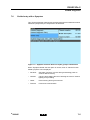
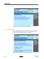
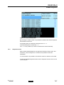
If the "Manual" button is selected, all possible systems will be displayed, even
systems that are not mounted on the vehicle. To select the required variants,
carry out the following steps:
1. Select a system by pressing the name of the system. The installation variants of the system are displayed automatically on the screen.
The system name is marked with a bar.
5-4
©
200845
DAVIE XDc II
Vehicle Identification
Figure 5-4 Manual system selection
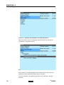
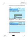
2. Select one of the listed variants based on the DAF Mainframe or Parts
Rapido online, Helpdesk or other similar information.
Figure 5-5 Manual system variant selection
The selection is marked with a bar. Confirm the selection with the "Forward
/ >"button. The Direct Test or Guided Diagnosis screen is displayed.
By selecting the system name, it is possible to switch back to the system
selection list.
©
200845
5-5
DAVIE XDc II
Vehicle Identification
Figure 5-6 System selection, Go to "Installation variants"
3. If more systems need to be selected, use the "Go to" button and select
"ECU Installation Variants". The already chosen system installation variants
are displayed.
Figure 5-7 Overview: manual selection
4. Press the "Back / <" button to switch to the system selection screen and
select a system. Like step 1, figure 5-4.
Repeat steps 1 to 4 to select more systems.
5-6
©
200845
DAVIE XDc II
Vehicle Identification
5.4
Deselect ECU Installation Variant
After the automatic or manual variant selection is finished, DAVIE XDc II
displays the Direct Test or Guided Diagnosis screen.
If a system needs to be deselected, use the "Go to" button and select "ECU
Installation Variants".
Figure 5-8 System variant list (deselected Variant)
The variant names are displayed. Now it is possible to deselect and reselect
systems and variants from the list.
A selected system is marked by a black bar, a deselected system is marked by
"(" and a highlighted bar. The ")" is only visible if you select or deselect the
variants manually.
NOTE
Deselecting automatically selected variants should be avoided. The use of an
incorrect variant has a direct influence on the proposal of test procedures.
A selection of a variant different to the proposed variant is only necessary if the
installation variant is definitively changed in the workshop and the Parts Rapido
Subset database or the central truck ECU is not already updated.
The system continues with the "Forward / >" button.
A list with the systems, selected in the "ECU Installation Variant" screen, will be
displayed.
©
200845
5-7
DAVIE XDc II
Vehicle Identification
5-8
©
200845
DAVIE XDc II
Direct Testing
6
DIRECT TESTING
6.1
Overview
This functionality is primarily used to interrogate and erase ECU fault memory
and utilize various in- and outputs, dependant on the relevant test procedures
selected. The function "Direct Testing" must also be used for programming and
calibrating.
The knowledge and experience of the user is fully utilized, enabling the "Direct
Testing" to provide a "short cut" to the suspected fault. This functionality
supplements the "Guided Diagnostics" facility, ensuring the most efficient route
to the fault remedy.
The results of the diagnostic session and manually saved information will be
stored in a log file, which can be read out in the Administrator menu.
Figure 6-1 Start screen: User Login
To enter the Direct Testing mode, press the "Direct Testing" button on the
"Start" screen.
©
200845
6-1
DAVIE XDc II
Direct Testing
6.2
Vehicle Identification
Whichever diagnostic function is selected in the Start screen (Direct Testing,
Guided Diagnosis), DAVIE XDc II will attempt to identify the vehicle and the
system variants automatically by using the chassis number and the Parts
Rapido Subset database in the DAVIE XDc II.
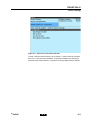
Figure 6-2 Direct Testing: test selection
By continuously selecting from the displayed options, the user can refine the
selection until the desired vehicle test procedure is displayed. A system has
been selected in the following example. Once this option is selected, more
options are displayed.
6-2
©
200845
DAVIE XDc II
Direct Testing
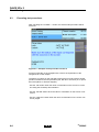
Figure 6-3 Direct Test: procedure selection
To start a selected test procedure, the "Forward / >" button must be activated.
If there is no test procedure available, a message will appear. By selecting a
procedure with sub-procedures, a sequence of the procedures will be started.
©
200845
6-3
DAVIE XDc II
Direct Testing
6.3
Executing test procedures
After activating the "Forward / >" button, the selected test procedure will be
executed.
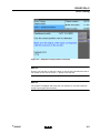
Figure 6-4 Example of test procedure screen 01
For the functionality of the navigation bar, refer to the explanation of the
navigation bar in this chapter.
The button or buttons on the right side of the screen must be used to answer
questions related to the test procedure (OK, Not OK or unknown) or to open a
document (Block- or Section diagram).
- Use the "OK" button when the value or information on the screen is correct
according the workshop documentation.
- Use the "Not OK" button when the value or information on the screen is not
correct.
- Use the "Unknown" button when the value or information on the screen can
not be judged.
6-4
©
200845
DAVIE XDc II
Direct Testing
Figure 6-5 Example of test procedure screen 02
NOTE
Use the "OK, Not OK or unknown" button to exit the test; otherwise the test is
not closed. Do not use the "back / <" button to exit the test.
NOTE
The system is intelligent and tracks the user selections. The test results are
saved in the log file and Test Plan.
©
200845
6-5
DAVIE XDc II
Direct Testing
Figure 6-6 Example of a block diagram
6.4
Navigation bar
By pressing the "Navigation Bar" buttons, the user can quickly navigate to
various parts of the program. The buttons "Go To" and "Help" contain Windows
type "pull up" menus which are screen sensitive and whose contents change
according to the screen currently being displayed.
The two "Arrow" buttons ("Back / <" and "Continue / >") allow the user to move
forwards and backwards between screens.
If the "Back / <" button is pressed to exit a test, the test remains as running.
6-6
©
200845
DAVIE XDc II
Direct Testing
6.5
Go To button
During "Direct Testing", various options are available to the user in the pop up
menu of the "Go to" button. The contents of the "Go To" menu is dependent on
the actual screen. Some examples are listed below:
Figure 6-7 Variant: selection screen
Figure 6-8 Test procedure: selection screen
©
200845
6-7
DAVIE XDc II
Direct Testing
6.5.1
EXIT
This option exits the current test, ends the diagnostic session, and displays the
DAVIE XDc II start screen Figure 6-1.
Figure 6-9 Warning : Exit operation mode
6.5.2
Health Check
The option "Health Check" is only displayed within the "Go To" button in the
"ECU Installation Variants" and "Direct Test Selection" menu if an ECU is
selected.
This option reads all pending (active) fault codes within the system of all
selected ECU's in the "ECU Installation Variants" screen.
A "Health Check" is often the first test that is performed because the results
provide important diagnostic information that can guide further diagnostic
testing.
6.5.3
Fault Memory Contents
All faults which have been detected with the "Health Check" can be read out in
the "Fault Memory Contents".
These fault codes are very important for the user because almost every ECU is
capable of self-diagnosis and checks the sub-systems connected to the ECU.
This information allows the user to concentrate on the specific fault areas in the
vehicle.
The results of the "Fault Memory Contents" will be saved into the log file.
6-8
©
200845
DAVIE XDc II
Direct Testing
6.5.4
Documents
During testing, various documents can be displayed, such as drawings for
connectors, wiring diagrams or even instruction sheets. These documents are
"linked" to the system at relevant points during testing. For example, if a test is
being performed on a connector, a schematic of this connector, showing the
various pin connections, could be viewed.
The documents can be displayed via the "Go to" button when the system is
selected and by the buttons on the right side of the screen when available.
Figure 6-10 Open Documents
©
200845
6-9
DAVIE XDc II
Direct Testing
6.5.5
Test Plan
The test plan shows the list of the test procedures that have been executed.
The option "Test plan" is available during a diagnostic session. This plan is
organized by the DAVIE XDc II to provide useful information guiding the user to
a correct diagnosis as quickly as possible. The "Test plan" and the results will
be saved into the log file.
An example of a test plan shows the listing of the tests that have been executed.
Figure 6-11 Test plan
The user can select which part of the plan to execute next by pressing a
particular test, which will then be performed when the "Forward / >" button is
pressed.
The result of the test procedure is noted in front of the line. The following results
are possible:
1. OK The test procedure was completed with the result OK.
6-10
2. X
The test procedure was completed with the result Not OK.
3. ?
The result of the test procedure is unknown or the procedure was
interrupted. For example the test was closed by using the back button.
©
200845
DAVIE XDc II
Direct Testing
6.5.6
ECU Installation Variants
This option within the "Go To" menu on the Navigation Bar allows the user to
return to the screen which list the ECU options found for the vehicle.
6.5.7
Direct Test Selection Screen
Use this function in the "Go To" menu to switch back to the "Direct Test
Selection" and to select another system. The diagnostic session will be not
completed and all previous test results will be available until the "Direct Test"
function is terminated by using the "Exit" function.
6.6
Use of illustrations
During testing, various documents can be displayed, such as drawings for
connectors, wiring diagrams or even instruction sheets.
These documents are "linked" to the system at relevant points during testing.
For example, if a test is being performed on a connector, a schematic of this
connector, showing the various pin connections, could be viewed.
Figure 6-12 Selection of block diagram button in "Direct Test"
By pressing the corresponding button, "Adobe Acrobat©" will start up separate
of the DAVIE XDc II program. An index page could appear before the
illustrations are displayed.
©
200845
6-11
DAVIE XDc II
Direct Testing
6.6.1
Index page
In the index page the chassis number can be selected for the appropriate
illustrations.
Figure 6-13 Example of an "Index Page"
All blue items have a link to illustrations.
Figure 6-14 Example of a "Block diagram"
6-12
©
200845
DAVIE XDc II
Direct Testing
6.6.2
Explanation of buttons on the screen
The buttons can be divided in two categories:
1. Actions on one document concerning zoom functions
2. Actions between documents
Actions between documents
Green round arrows at the bottom of the screen:
With this buttons the previous document can be entered in the list of documents
which were already open.
Bleu arrows at the bottom of the screen:
With these buttons you can switch between documents which are already open.
Zoom functions
Zoom:
At the top of the screen a navigation bar is displayed.
When the magnifying glass is pressed the zoom function is selected.
You can enlarge the desired area by dragging a zoom window on the screen.
When the arrow near the magnifying glass is pressed you can choose some
zoom options.
For further information about the functions in Adobe Acrobat, please use the
"Help function" of Adobe Acrobat.
©
200845
6-13
DAVIE XDc II
Direct Testing
6-14
©
200845
DAVIE XDc II
Guided Diagnosis
7
GUIDED DIAGNOSIS
7.1
Principle op of Guided Diagnosis
Guided Diagnosis is primarily used to determine (point out) the possibly
defective elements (components). Where the function "Direct Testing" has to be
used for programming, calibrating or to directly test specific components,
"Guided Diagnosis" presents tests only based on the elements which are
suspected to be defective.
Why using Guided Diagnosis?
•
If you want to confirm suspicion without exchanging parts by trial & error
•
If you don't know which components to suspect
•
If you have a lack of knowledge about a vehicle function
•
If an error status is unclear (active/not active) symptoms can be used
•
Guided can and will tell you!
There are different methods, within Guided Diagnosis, to find the suspected
element (component):
1. Based on Fault codes (present in the ECU Fault Memory)
2. Based on Symptoms (deviant behaviour of Systems)
3. A combination of above
The best way to build a Test plan is using Fault codes (1), because this usually
generates a small list of suspected elements.
When no Fault codes are present the Test plan can be build on Symptoms (2).
The list of suspected elements can be much larger.
When Fault codes are present, but the list of suspected elements is still very
large, Symptoms can be added to decrease the list (3).
©
200845
7-1
DAVIE XDc II
Guided Diagnosis
7.2
Starting Guided Diagnosis
Figure 7-1 Start screen User Login
To enter the Guided Diagnosis Mode pres the "Guided Diagnosis" button on the
"Start" screen.
7.3
Vehicle Identification
Whichever diagnostic function is selected in the Start screen (Direct Testing,
Guided Diagnosis), DAVIE XDc II will attempt to identify the vehicle and the
system variants automatically by using the chassis number and the Parts
Rapido Subset database in the DAVIE XDc II.
For detailed information about vehicle identification, refer to the chapter
"Vehicle Identification" in this manual.
7-2
©
200845
DAVIE XDc II
Guided Diagnosis
7.4
Guided Entry
There two different main methods to build a test plan to solve the problem on
the truck.
Guided entry with:
•
Fault codes (present in the ECU Fault Memory)
•
Symptom (deviant behaviour of the truck)
Select the entry you want to use and it turns press the "Forward / >" button
Figure 7-2 Guided Entry
7.5
Guided entry with Fault code(s)
This method uses the fault codes, present in the ECU Fault Memory, to
determine which elements are suspected to be defective.
To read out all Fault codes, press the "Guided entry with Fault codes" in the
"Guided Diagnosis Entry" screen. After this selection the "Health Check" is
started automatically.
©
200845
7-3
DAVIE XDc II
Guided Diagnosis
Figure 7-3 Health Check
7.5.1
Health Check
The "Health Check" reads out all present Fault codes from the ECU fault
memory for all selected Systems, which are available on the vehicle.
When the ECU is being read out a "<==" will be displayed in blue colour on the
screen.
When fault codes are read, the text "Fault" will be displayed in red colour behind
the system.
When fault codes are read from the ECU, but no present Fault codes are found,
a " " will be displayed in green colour.
When fault codes are not implemented in the ECU, it will remain blank.
Press the "Forward/ >" button to go to the Test plan Overview.
NOTE
7-4
•
Only Pending errors are used by Guided Diagnosis.
•
When no Fault codes are present the Test plan cannot be build. Therefore
Guided Diagnosis will automatically switch over to Symptom selection
©
200845
DAVIE XDc II
Guided Diagnosis
7.6
Guided entry with a Symptom
This "Symptom Based" method uses the selected symptom to determine which
elements (components) are suspected to be defective.
Figure 7-4 Symptom selection based on repair group or observation
When "Symptom Based" the first option is chosen, a list of "Vehicle function
based symptom" tree is displayed.
©
200845
•
Driveline:
Generate / transmit / convert driving and braking power to
achieve desired velocity
•
Chassis:
Carrying and handling the load / directing the vehicle / exterior
lighting / body building
•
Cabin:
Driver working & living environment
•
General:
Fuses and communication
7-5
DAVIE XDc II
Guided Diagnosis
Figure 7-5 Systems with Symptoms for Guided Diagnosis
When the group of choice is selected the list will unfold to an overview of
“Symptoms” or “Symptom groups”.
Figure 7-6 Select Symptom
The "Forward / >" button will appear at the bottom of the screen. Now it is
possible to add the selected symptom to the “Test plan”.
Once the Symptom is accepted it is placed in a list, called the “Test plan
overview".
7-6
©
200845
DAVIE XDc II
Guided Diagnosis
7.7
Test plan
7.7.1
Test plan Overview
All detected faults or selected symptoms are displayed on this screen
Select the (grouped) fault or symptom you want to solve.
Figure 7-7 Test plan Overview after "Health Check"
Figure 7-8 Test plan Overview after symptom selection
©
200845
7-7
DAVIE XDc II
Guided Diagnosis
Once the selection is made, press the "Forward/ >" button. Guided will be
configured to set up the tests.
Figure 7-9 Configuration of Guided Diagnosis
7.7.2
Building a Test plan based on Fault codes and Symptoms
This method uses not only the read out Fault codes but also extra selected
Symptoms to determine which elements are suspected to be defective.
To add Symptoms press the "Go to" button on the navigation bar and select
"Symptom Report".
7-8
©
200845
DAVIE XDc II
Guided Diagnosis
Figure 7-10 Select Symptom Report
7.7.3
Test plan screen lay out
Figure 7-11 Test plan
©
200845
7-9
DAVIE XDc II
Guided Diagnosis
The screen is divided in two sections:
•
The upper half displays the Suspected Elements
Which elements are suspected is purely based on the read out Fault codes
and selected Symptoms. The elements are sorted on the level of suspicion;
the most upper element is the most suspected.
•
The lower half displays the proposed tests
The list is based on the sequence and availability of the tests, which are
best to be executed. Generally the most upper test is the most effective test
(the user is obviously free in selecting any other test of the list).
The level of suspicion is also indicated by use of colours.
Dark red
Faulty (tested
Red
Very suspected
Yellow
Suspected
Green
Ambiguous
Figure 7-12 Suspicion level of components
The result of the test procedure is noted in front of the line. The following results
are possible:
-
The Test procedure is not yet executed.
OK The Test procedure was finished with the result OK.
7.7.4
X
The Test procedure was finished with the result not OK.
?
The result of the Test procedure is unknown or the procedure was
interrupted.
Executing tests
Proposed tests occur in different forms.
1. Direct Test
2. Symptom test or Check test
3. Measurement test
When the test result is
7-10
•
Correct: press "OK"
•
Incorrect: press "Not OK"
•
Uncertain: press "Unknown".
©
200845
DAVIE XDc II
Guided Diagnosis
NOTE
It is very important for Guided Diagnosis that the answers and implicitly at the
end of the test is corresponding with the vehicle behaviour.
Incorrect answers will lead to a different suspected element.
7.7.4.1
Direct test
When a Direct Test will be proposed, the same test as used for Direct Testing
will be used to determine the defectiveness of a component.
Figure 7-13 Example of a Direct test
7.7.4.2
Symptom test or Check test
When a test is proposed to check a symptom, Guided Diagnosis would like to
have more information on the vehicle behaviour. It will require some actions
from the user and will ask if the behaviour of the vehicle was as expected when
these actions were executed.
©
200845
7-11
DAVIE XDc II
Guided Diagnosis
Figure 7-14 Test to research presence of Symptom
7.7.4.3
Measurement Test
When a measurement test is proposed, Guided Diagnosis would like to have
more information on the status of wiring and components. In most cases it
would be a test to determine the voltage on a connection.
Figure 7-15 Test to research short and / or open circuits
7-12
©
200845
DAVIE XDc II
Guided Diagnosis
7.7.5
Function Component selection
With Guided Diagnosis it is also possible to test a component individually or to
select a test which is linked to other components then the currently listed in the
Test plan. Adding extra information, into the reasoning mechanism, may be
useful to guide you quicker to the defect.
To add a Test: press the "Go to" button on the navigation bar and select
"Function / Component Selection".
Figure 7-16 Select Function/ Component Selection
After selecting the System of choice a list of linked components, when available,
will be displayed.
©
200845
7-13
DAVIE XDc II
Guided Diagnosis
Figure 7-17 List of linked components
From this list any component can be selected. After selecting a component, by
pressing the "Forward / >" button in the bottom right of the screen, the User Test
plan is added to the Test plan screen.
If more tests are available, a pop-up screen will appear, displaying these tests.
In this screen it is possible to select the requested test.
When a test is selected, press the "OK" button and the test is added to the user
Test plan.
Figure 7-18 Select a test
7-14
©
200845
DAVIE XDc II
Guided Diagnosis
If there is only one test available for the selected component the user Test plan
is started directly after continuing from the component selection screen.
Figure 7-19 Test plan including user Test plan
7.8
Extra options
7.8.1
Fault Memory Contents
When the System, interrogated through the health check contains one or more
Fault codes, the contents can be displayed with the Fault Memory Contents.
The Fault Memory Contents can be viewed from the "pop up" menu under the
"Go To" button.
These Fault codes are very important for the user because almost each ECU is
capable of self-diagnosis and checks sub-Systems connected to the unit.
This information allows the user to concentrate on the specific fault areas on the
vehicle.
©
200845
7-15
DAVIE XDc II
Guided Diagnosis
Figure 7-20 Fault memory content
This screen displays the currently present Fault codes. Equal to Direct Testing
every Fault code is represent with a Fault code number and text.
7.8.2
Deselecting Systems
In order to leave one or more Systems out of the Test plan, deselect those
Systems before performing the Health Check.
This can be useful:
•
When a System produces Fault codes, but has no relation to the complaint.
•
To speed up Diagnostic sessions, by deselecting those Systems which are
not related to the complaint.
NOTE
When Health Check already has performed, without deselecting Systems, Exit
and restart Guided Diagnosis via selecting "Exit" from the "pop up" menu button
under the "Go to" button then select "Guided Diagnose" in the startscreen.
When the automatic vehicle identification is complete the Guided Diagnosis
entry screen is displayed. Use the "Go to" button and select "ECU Installation
Variants".
7-16
©
200845
DAVIE XDc II
Guided Diagnosis
Figure 7-21 Deselected Variant
By touching the variant names, it is possible to deselect and reselect Systems
and variants from the list.
A selected System is marked by a black bar and / or ")".
A deselected System is marked by "(".
The ")" is only visible if you select or deselect the variants manually.
7.8.3
Suspend session
When quitting Guided Diagnosis, all gathered information (Fault codes, test
results etc.), will normally be lost. Therefore it is possible to save this
information.
In a next session it is possible to continue the work from where it was ended.
To save the Guided Diagnosis session select "Suspend" from the "Go to" menu
in the Test plan.
©
200845
7-17
DAVIE XDc II
Guided Diagnosis
Figure 7-22 Select Suspend
When selecting suspend, a screen will be displayed with the options:
•
Pause: This will stop the work only temporarily, and it will not be possible to
do anything else, until the pause is ended.
•
Suspend: This will save the current diagnostic information, like suspected
elements and executed tests, so that it may be started again in the future.
When "Suspend" is chosen, the current diagnostic session is ended.
Figure 7-23 Work suspension
7-18
©
200845
DAVIE XDc II
Guided Diagnosis
To continue with a previously suspended session, it is required to select the
option "Diagnosis Job" from the "Go to" menu in the ECU installation variants
screen.
Figure 7-24 Select Diagnosis Job
When selecting "Diagnosis Job", a screen with the diagnostic jobs will appear.
By selecting the diagnosis job, it is possible to use or delete the saved session.
Figure 7-25 Select suspended diagnostic session
©
200845
7-19
DAVIE XDc II
Guided Diagnosis
To delete a session select the required session and press the "Delete" button
in the bottom right of the screen.
To continue with the diagnostic session of choice, select it and press the "Use"
button in the bottom left of the screen.
When a selection is made a screen will appear indicating that the vehicle must
be connected.
Figure 7-26 Connect DAVIE XD to the correct vehicle
After connecting the DAVIE XDc II to the vehicle, via the VCI, and pressing "OK"
in this screen, Guided Diagnosis will continue reasoning from the latest Test
plan screen, where Guided Diagnosis was suspended.
When for the second time a session is suspended (for the same truck) press
"Repeat" to overwrite the old session, or press "OK" to add this session. The
date and time of saving will help to identify the exact session.
Because Guided Diagnosis is based on the principles that a Symptom or Fault
code is always related to certain vehicle behaviour, it is important that no repairs
have been made to the vehicle that may have caused the complaint. In case a
repair is executed the information is no longer consistent with the Test plan and
it is better to start a new diagnostic session.
7-20
©
200845
DAVIE XDc II
Guided Diagnosis
7.9
Quitting Guided Diagnosis
When Guided Diagnosis is finished, it is possible to end it by selecting "Exit"
from the "Go to" pop-up menu in any screen.
When exiting, a screen will appear to inform that is possible to reset the Fault
codes from the units.
Figure 7-27 Decision: erase fault memory content
When quitting Guided Diagnosis, the following screens could appear:
•
Switch contact Off/ On
•
Systems needs time to refresh
NOTE
When the Fault codes are reset at the end of a diagnostic session, both pending
and stored errors will no longer be available for interrogation in Guided
Diagnosis or Direct Test.
©
200845
7-21
DAVIE XDc II
Guided Diagnosis
7-22
©
200845
DAVIE XDc II
Administration
8
ADMINISTRATION
8.1
Overview
Administration groups together basic set-up functions for the DAVIE XDc II. To
access all Administration settings, you must login as administrator.
The following Administration functions are available for the administrator:
8.2
•
"Install update":
Installation of update 1st language.
•
"Change language":
Change to the second language (only if 2nd language is installed).
•
"Dealership Identifier":
Input or change of DAVIE XDc II name in "Information Window".
•
"Initial Graphic":
Selection of the initial picture on the startscreen.
•
"Version information":
Version information about the Runtime, Application and Parts Rapido
Subset
•
"Contents of application data":
Information about the installed application data.
•
"Passwords":
Add or change Users and Passwords.
•
"Log files":
Read out the stored Log files:
•
"Helpdesk log files":
Read out the stored helpdesk log files.
•
"Vehicle test files":
Read out the stored Vehicle test files.
•
"Service level key":
The Service level key can only be used in confer with your Local Helpdesk.
Start Administration
Administration is activated from the start screen by selecting the Administration
button after login as the administrator, Master Technician and Senior
Technician.
©
200845
8-1
DAVIE XDc II
Administration
Figure 8-1 Start screen after login as the administrator
Choose this button in the start screen, the DAVIE XDc II will offer a list of
accessible functions (see Figure 8-2).
Administrator
Master
Technician
Senior
Technician
Install Update
X
X
X
Change language
X
X
X
Dealership Identifier
X
Initial Graphic
X
Version information
X
Contents of application data
X
Passwords
X
Log files
X
X
X
Helpdesk Log Files
X
X
X
Vehicle test files
X
X
X
Service level key
X
Figure 8-2 Table with administration functions per user
8-2
©
200845
DAVIE XDc II
Administration
8.3
Select Function
Login as "Administrator" and select the "Administration" button in the start
screen (see Figure 8-1), the following screen will appear. It contains a list of all
accessible functions in Administration mode.
Figure 8-3 Administration screen: select function
Select any function with the selection bar. This calls up a screen in which you
can edit the function.
In the top right-hand information window, the DAVIE XDc II equipment number
and the dealership code are displayed automatically as soon as it has been
entered. The dealership identifier is permanently displayed during
Administration mode.
Using the "Back / <" button, you can return from any administration function
screen to the Administration screen and from there to the system start screen.
©
200845
8-3
DAVIE XDc II
Administration
8.4
Install update
There are two ways to update the DAVIE XDc II software.
You can install updates like the Runtime, Application and Parts Rapido Subset
by new delivered CD's or you can update via the Dealernet.
8.4.1
Install update of a new Runtime CD:
For the update of the DAVIE XDc II application, a separate instruction will be
send along with the Runtime update CD.
8.4.2
Install update of a new delivered Application CD:
1. Insert the CD you want to install use in the DVD drive.
2. Close the automatic started Windows XP screen that pops up.
3. Select the function "Install update".
4. You can install up to two languages. Select the language(s) and press
"OK".
If only one language is selected, go to step 6.
Figure 8-4 Select language of Application
NOTE
When a first language already has been installed, a second language can be
added. See chapter "Install second language".
5. Select which language has to be the first language.
8-4
©
200845
DAVIE XDc II
Administration
Figure 8-5 Select first language of Application
Figure 8-6 Select first language of Application
6. Press "OK" to install the selected update(s).
The application(s) will be installed on the DAVIE XDc II. A progress
indicator allows you to track the installation process.
As soon as it is finished, the DAVIE XDc II jumps to the start screen.
7. Remove the CD from the drive.
NOTE
You can only load CDs that are no older than the period of validity set by DAF.
CDs older than that will be rejected.
Any second language that was previously installed will be deleted during an
update.
©
200845
8-5
DAVIE XDc II
Administration
8.4.3
Install a second language
By selecting "Install update", you can also initiate the installation of a second
language with the same version as the first language.
This is only necessary if a second language is to be used on the same DAVIE
XDc II. In this case, only the language-specific parts of the software (knowledge
bases, text files, etc.) are installed.
Up to two different languages can be installed on one DAVIE XDc as long as
the software versions remain identical to each other. The first language can be
overwritten with another language or the second language can be added.
Procedure to install the 2nd language
1. Insert the application CD in the DVD drive. (The same version as 1st
language)
2. Close the automatic started Windows XP screen that pops up.
3. Select the function "Install update".
4. Select the desired language and press "OK".
5. Select "Add" to add the second language.
Figure 8-7 Select "Replace first language or add second language"
6. Confirm the security prompt to update or install the inserted CD.
7. The contents of the CD are installed in the Basic Unit. An on-screen
progress indicator allows you to track the installation process.
8. As soon as it is finished, a message will appear indicating that the system
will be restarted to complete installation process.
9. Remove the CD from the drive.
10.Confirm the message box.
11. The application will restart automatically.
12.After rebooting, the system and the application data are changed to the
new second language.
8-6
©
200845
DAVIE XDc II
Administration
8.4.4
Install update of a new Parts Rapido Subset CD
1. Insert the Parts Rapido Subset CD you want to install in the DVD drive.
2. Select the function "Install update".
Figure 8-8 Confirm for Parts Rapido Subset installation
3. Press "OK" to install the selected update.
4. The Parts Rapido Subset will be installed on the DAVIE XDc II. A progress
indicator allows you to track the installation process. As soon as it is
finished, the DAVIE XDc II jumps to the start screen.
8.4.5
Install update(s) from DAVIE XDc Download.
1. Copy the files to the media (do not use a space in the folder name).
2. Insert the media you want to use in the DAVIE XDc II.
3. Select the function "Install update".
4. If the files have not been copied to the root of the media a screen pops up.
5. Navigate to the appropriate folder's label file and click OK.
6. Confirm the security prompt to install the inserted CD.
7. The update will occur.
©
200845
8-7
DAVIE XDc II
Administration
8.4.6
Install update from Parts Rapido online
1. Copy the unzipped files to the media (do not use a space in the folder
name).
2. Insert the media you want to use in the DAVIE XDc II.
3. Select the function "Install update".
4. If the files have not been copied to the root of the media a screen pops up.
5. Navigate to the appropriate folder's label file and click OK.
6. Confirm the security prompt to install the inserted CD.
7. The single chassis update will occur.
8.5
Change language
To switch between the languages, until a new application CD is installed, an
additional "Change language" selection button is available in administration. It
is also possible for the normal user to change the language.
Figure 8-9 Select: Change language
NOTE
Each time you change the language, the application will be restarted.
8-8
©
200845
DAVIE XDc II
Administration
8.6
Dealership identifier
The DAVIE XDc II could be assigned your with a dealership identifier to easily
identify the DAVIE XDc II.
When the function has been selected with the selection bar, an alphanumeric
keyboard appears on screen. Use the "SH" button to switch between a
keyboard with upper case and special characters or with lower case characters
and numbers.
Enter the data in up to two lines each using the 60 letters and digits available,
spaces and any of the following special characters: , + - * / = # &.
NOTE
Language-specific special characters are not available.
Figure 8-10 Keyboard
8.7
Initial Graphic
The initial graphic is displayed graphic in the start screen.
When you select the "Initial Graphic" function in the function list, a preview of
the stored "Initial Graphics" is displayed.
Use the "Forward / >" button to go step by step through all available "Initial
Graphics". Use the "Back / <" button to accept the displayed graphic in the start
screen.
©
200845
8-9
DAVIE XDc II
Administration
Figure 8-11 Select "Initial Graphic"
8.8
Version information
When you select the "Version information" function in the function list, the
screen displays version information about the installed Runtime, Application
and Parts Rapido Subset.
8-10
©
200845
DAVIE XDc II
Administration
8.9
Contents of application data
When you select the "Contents of application data" function in the function list,
the screen displays information about the application data installed on the
system (information is only available in English).
Figure 8-12 Example of the “Contents of application data”
8.10
Passwords
NOTE
This function is only available when logged in as administrator.
In the "Passwords" screen, users of the DAVIE XDc II system and passwords
can be added and changed. All entered users are displayed with their hidden
passwords and user levels.
©
200845
•
To edit an entry, select the relevant element in the "User ID" column. A
dialog box opens in which you can edit the user level of the selected user.
•
To add an additional user, select an empty element in the "User ID" column.
•
To enter or change passwords, select the corresponding element in the
"Password" column.
8-11
DAVIE XDc II
Administration
NOTE
Depending on the different user levels "Senior Technician" and "Master
Technician" only those test procedures to which the specific technician level
has access will be displayed by the DAVIE XDc II and implemented by the
technician.
Only the Administrator has the right to the Password settings.
If a column is selected, a virtual keyboard appears and a new user can be
added or a selected one can be changed.
8.11
Log Files
Each Diagnostic Session of the DAVIE XDc II is automatically logged into a log
file on the hard disk.
You can use this function to view the saved data from "Direct Test" or "Guided
Diagnose" which is stored into the log files with Adobe Acrobat.
The files can be printed out or exported to a USB-Stick or other media.
When you select the "Logfiles" function a Windows box opens and the desired
"Log File" can be selected.
Figure 8-13 Selection of "Logfiles" in the function list
8-12
©
200845
DAVIE XDc II
Administration
Figure 8-14 Example of the "Windows Explorer screen"
Figure 8-15 Example of the "Content of a logfile"
©
200845
8-13
DAVIE XDc II
Administration
8.12
Helpdesk Log Files
The 'Helpdesk Log files' equal as the "Logfiles" but saved in the English
language.
NOTE
These files are very valuable for the Helpdesk. If the DAVIE XDc II generates
an error, please send the corresponding "Helpdesk Log Files" to the Helpdesk.
8.13
Vehicle test Files
This function works like "Log Files" but it displays "Vehicle test files". In contrast
to log files, these are not automatically generated but written only when
instructed to do so in the function test.
8-14
©
200845
DAVIE XDc II
VCI Configuration Manager
9
VCI CONFIGURATION MANAGER
VCI Configuration Manger is a software program to:
9.1
•
View the status of the VCI.
•
To configure the VCI according to the user's requirements.
•
To display VCI specific information.
•
To configure the VCI Configuration Manger according to the user's
requirements.
VCI Tray Icon
The tray icon is similar to the VCI symbol on the front side of the housing and is
shown in the system tray. The tray icon displays the status of the VCI
connection.
The standard functionality connection status between DAVIE XDc II and VCI:
- White: Disconnected
- Blue:
USB
- Green: Excellent radio communication is possible with good data
throughput.
- Yellow : Sufficient radio communication is possible, reduced data throughput
may occur.
- Red:
Poor no sufficient radio communication possible.
Figure 9-1 VCI Tray Icon
Hovering
When the mouse pointer hovers over the VCI tray icon for 1 second, the status
is displayed for approx. 5 seconds:
•
Connection status between DAVIE XDc II and VCI: connected or
disconnected.
•
Connection type: WLAN (radio), USB or not available, if status is
disconnected.
•
Network name SSID, if available.
Double click left
With double click on the VCI tray icon with the left mouse button the VCI
Configuration Manager will be started directly.
©
200845
9-1
DAVIE XDc II
VCI Configuration Manager
Figure 9-2 VCI Tray Icon double left click
Single click right
With a click on the VCI tray icon with the right mouse button a context menu is
displayed with the following sections:
•
About: The VCI Configuration manager software version will be displayed.
•
Start VCI Configuration Manager: The VCI Configuration Manager will be
started directly.
•
Status Info: The same information when hovering over the tray icon.
•
Exit: Close the system tray icon.
Figure 9-3 VCI Tray Icon single right click
9-2
©
200845
DAVIE XDc II
VCI Configuration Manager
9.2
The WLAN Quality Indicator
9.2.1
General
In order to detect interferences of the communication via WLAN between the
DAVIE laptop and the Blue VCI, the quality of the WLAN connection can be
observed. This is done by a small display which shows a rating of the WLAN
connection quality. The WLAN Quality Indicator is controlled by the VCI Tray
Icon and the Configuration Manager.
It is updated every second. An average response time to changes of the
connection quality of four seconds is aimed.
As long as the Blue VCI is connected via USB the display is switched off.
Figure 9-4 WLAN green
The WLAN Quality Indicator is also visible while the DAVIE application is
running. Therefore it is always on top position. The appearance of the display
dialog is adapted to the screen resolution.
After installation and when the USB-cable is disconnected the display is visible.
The WLAN Quality Indicator can be moved and closed.
The location is stored so that at a restart the display is shown at the latest saved
position.
9.2.2
Interface
The WLAN Quality Indicator can be turned on and off with the VCI Tray Icon.
The context menu entry shows a check mark if the display is active.
The WLAN Quality Indicator can also be turned on and off with a check box of
the “Common Settings” in the VCI Configuration manager menu.
©
200845
9-3
DAVIE XDc II
VCI Configuration Manager
9.2.3
Rating of the WLAN connection quality indicator
The WLAN Quality Indicator is defined in four quality categories.
Figure 9-5 WLAN all collors
Green
Excellent
Radio Communication is possible with good data
throughput.
Yellow
Sufficient
Radio Communication is possible, reduced data
throughput may occur.
Red
Poor
No sufficient radio communication.
None
No connection
No radio communication.
NOTE:
As long as the Blue VCI is connected via USB the display is switched off.
9-4
©
200845
DAVIE XDc II
VCI Configuration Manager
9.3
Start up the VCI Configuration Manager Program
First close the DAVIE XDc II application before start up the VCI Configuration
Manager with the shortcut in the Windows Start menu or double-click the VCI
Tray Icon in the System Tray.
Figure 9-6 VCI Configuration Manager Icon
The VCI Configuration Manager provides four property screens:
•
Status Info:
View the software versions and communication settings
•
Basic Setup:
Easily configure the VCI setting
•
Advanced Setup: For advanced settings (network specialists)
•
Common Setup:
Configuration utilities, VCI buffer settings and selftest
NOTE:
Some options can be greyed out in the VCI Configuration Manager.
1. If the user is not logged in as Windows administrator:
a. Basic Setup can not be used
2. When the Blue VCI is not connected via USB, only the next setting can be
read out or changed:
a. Read out Tester firmware version
b. Read out Tester Software Bundle
c. Enable or disable WLAN Quality Indicator
d. Change the language of the VCI Configuration Manager
©
200845
9-5
DAVIE XDc II
VCI Configuration Manager
9.3.1
Status info
The status information screen shows specific information about the VCI.
Figure 9-7 Status info screen
9-6
©
200845
DAVIE XDc II
VCI Configuration Manager
Status Info
Connection Status
This shows the connection status between the
DAVIE XDc II and the VCI.
Connection type
This shows the connection type of the VCI. This
must be USB, WLAN or ---. The dash (---) will be
displayed when the VCI is not connected.
Network name (SSID)
The Network name (SSID) for the WLAN
(radio) Connection that is currently configured
on the VCI.
VCI Serial Number
This shows the VCI serial number which is
connected to the DAVIE XDc II. The
information is only available if the VCI is
connected by USB.
VCI MAC address
This is an address that is required for every
port or device that connects to a network. Use
these addresses to locate specific ports in the
network. The information is only available if the
VCI is connected by USB.
VCI Firmware Version
The version number of the VCI currently
connected. The information is only available if
the VCI is connected by USB.
Tester Firmware Version
This shows the version of the VCI firmware
which is installed on the DAVIE XDc II.
Tester Software Bundle
This shows the version of the VCI Software
which is installed on the DAVIE XDc II.
Save Report File
Press this button to generate a report file which
could be used for support from the helpdesk or
to archive the current settings.
OK
The VCI Configuration Manager closes
automatically. If changes are made in other
screens these changes will be set.
Cancel
The VCI Configuration Manager will close
without any changes
NOTE
If pressed OK, a confirmation screen is displayed.
VCI and Tester settings will be overwritten !
Be sure that "Windows automatic wireless network configuration" is enabled.
See the User manual for more information.
Normally the "Windows automatic wireless network configuration" are already
been set at delevery. These settings must be dona only after a complete
reinstallation of Windows XP.
©
200845
9-7
DAVIE XDc II
VCI Configuration Manager
To check this setting, use the following instructions:
- Press with the <right touchpad key> on the Wireless Zero Configuration tray
icon.
- Select <Use Windows to manage WI-Fi>
- Then click "Start", click "Control Panel", click "Network and Internet
Connections", and then right click "Wireless Network connection", click
"Properties" and chose "Wireless Networks".
- The checkbox must be selected.
NOTE
The firmware version may only differ from the DAVIE XDc II and VCI right after
a VCI software update on the DAVIE XDc II. The firmware on the VCI will be
updated when the DAVIE XDc II application is started next time. This update
takes approximately one minute time.
9.3.2
Basic Setup
This screen is normally used to select a Wireless network adapter or to change
the VCI-ID Network Name (SSID).
If more than one VCI is used in the same workshop, the Basic Setup can be
used to easily setup a unique VCI-ID Network Name (SSID).
First connect the USB cable between the VCI and the DAVIE XDc II and
connect the VCI with the Vehicle Diagnostic Cable to the vehicle before
selecting the "Basic Setup" screen.
Figure 9-8 Basic Setup screen
9-8
©
200845
DAVIE XDc II
VCI Configuration Manager
Basic Setup
Network Adapter
Choose the Wireless Network Adapter that has
to be used to communicate with the VCI.
Normally the internal Wireless Network
Adapter of the DAVIE XDc II is pre selected.
The internal Wireless Network Adapter is
prefered.
Network Name (SSID)
The default Network Name is VCI-01. This is
the default network name between the DAVIE
XDc II and the VCI.
OK
The settings will be changed in the VCI and
DAVIE XDc II and the Configuration Manager
closes automatically.
Cancel
The VCI Configuration Manager will close
without any changes
NOTE
The network name must be unique. If other VCI's or Wireless Networks nearby
are using the same name, change the network name.
The Network name (SSID) will be stored in the VCI and on the local Wireless
Network Adapter which was selected above.
NOTE
The configuration is automatically created and applied to the VCI and DAVIE
XDc II.
The "Basic Setup" sets a WEP-key secured network connection between VCI
and the DAVIE XDc II.
9.3.3
Advanced Setup
NOTE
The "Advanced Setup" only configures the VCI settings. Configuration of the
DAVIE XDc II must be set using programs provided by Windows or the
manufacturer of your wireless network adapter hardware.
Therefore only use the Advanced Setup when you have knowledge about
Windows XP and wireless network settings.
Only the VCI configurations are displayed and are read at the start-up of the VCI
Configuration Manager.
©
200845
9-9
DAVIE XDc II
VCI Configuration Manager
First connect the USB cable between the VCI and the DAVIE XDc II and
connect the VCI with the Vehicle Diagnostic Cable to the vehicle before
selecting the "Advanced Setup" screen.
Figure 9-9 Advanced Setup screen
Wireless Network Configuration
Network Name (SSID)
Choose a Network Name (SSID) that is not
used by other Wireless Networks nearby.
IP-Address
IP-Address of the VCI in the Wireless Network.
Subnetmask
Subnet Mask for the VCI used in the Wireless
Network. Choose the appropriate subnet mask
for your network from the listed values.
Default Gateway
Default Gateway used by VCI to connect to
other networks.
Network Type
Infrastructure:
Connection with an Access-Point.
Ad-Hoc:
For a direct connection between DAVIE XDC II
and VCI
Channel
RF channel IS used for wireless
communication.
NOTE
Please take care. The selected RF channel has to conform to the local
regulations of your country.
9-10
©
200845
DAVIE XDc II
VCI Configuration Manager
Wireless Network Security
Security
None:
No encryption: no security.
WEP:
Wired Equivalent Privacy: basic security
WPA:
Wi-Fi Protected Access: high security (only
available in infrastructure networks).
Authentication
WEP:
Open / None: no authentication / Shared:
shared key authentication (not recommended
as it offers a security vulnerability).
WPA:
Pre Shared Key (PSK).
Encryption
Length of encryption key.
WEP:
64 bit: offers only low security
128 bit:
recommended.
WPA:
TKIP or TKIP+WEP.
Key Type
Hex:
Enter the key in hex format (for 128 bit key
enter 26 characters, for 64 bit key enter 10
characters)
Passphrase (ASCII):
Passphrase (ASCII): Enter the key in ASCII
format (for 128 bit key enter 13 characters, for
64 bit key enter 5 characters).
Key
Type the key which will be used for encryption
of the data in the Wireless Network WPA: 8 …
63 characters.
Retype Key
Must be the same key as above to verify that
the key has not been mistyped.
Advanced Settings
Auto fallback
©
200845
Enabled:
The best working data rate is used. As quality
of data transmission deteriorates with distance
data transmission rate (TxDataRate) is
decreased to keep the connection alive.
Disabled:
The connection drops when transmission
quality is not sufficient for that data rate any
more.
TxDataRate
Datarate for transmission (only available if
Auto fallback is not enabled). The higher the
data rate the shorter is the distance for a stable
connection to the VCI.
MTU Size
Maximum Transfer Unit Size: TCP Parameter,
only used by Network Administrators.
9-11
DAVIE XDc II
VCI Configuration Manager
ARP Cache (sec.)
Address Resolution Protocol Cache expiration
time: TCP Parameter, onlyused by Network
Administrators.
TCP Keepalive Time (sec)
TCP Parameter, only used by Network
Administrators.
Connection Management
Enabled:
Disabled:
Connection Management is active.
Two profiles ("Preferred"/"Alternative") are
supported. After power up the VCI configures
itself and uses profile "Preferred". If no
connection from DAVIE is established within a
certain time, VCI switches its configuration to
profile "Alternative". In this mode it waits an
unlimited time for incoming connections.
Connection Management is not active.
Profile
Preferred:
Configure profile "Preferred".
Alternative
Configure profile "Alternative".
Profile switching time (sec) Waiting time to switch to other profile if no
communication is established with preferred
profile.
NOTE
For the Preferred and the Alternative profile the same IP address has to be
used. To restart this process the VCI has to be powered again.
Load / Save / Delete Profiles
Save Profile
Save the configuration in a profile file.
9.3.4
Load Profile
Load the configuration from a previously saved
profile file.
Delete Profile
Delete a previously saved profile file.
Common Settings
This page contains status information and controls features of the VCI and VCI
Configuration manager settings which are not in context with Basic Setup:
9-12
•
Language selection VCI Configuration Manager.
•
Enable/disable WLAN Quality Indicator.
•
Setting VCI buffer time.
•
Enable/disable VCI buffering.
•
Selftest.
©
200845
DAVIE XDc II
VCI Configuration Manager
Only the language for the user interface of the Configuration Manager can be
selected independent of the connection of the VCI to the DAVIE XDc II. All other
settings are only available with USB connection.
Figure 9-10 Common Settings screen
VCI WLAN module
WLAN enabled
Enabled
The WLAN module of the VCI is activated.
A WLAN connection can be used for
communication.
Disabled
WLAN cannot be used. Only cable
communication via USB is possible.
Enable WLAN Quality Indicator
Enabled
The WLAN Quality Indicator is activated on top
of the screen.
(not on top of the screen when VCI is
connected by USB)
Disabled
WLAN Quality Indicator is not present on top of
the screen.
NOTE
Please take care. The use of wireless communication has to conform to the
local regulations of your country.
©
200845
9-13
DAVIE XDc II
VCI Configuration Manager
VCI Buffering
Enabled
When the ignition is switched off, the VCI is
buffered by the battery.
Disabled
No buffering when VCI is disconnected from
power supply.
Buffer Time
Time the built-in battery buffers VCI during the
vehicle ignition is switched off.
The buffer time for ignition status handling can
be chosen between 20 and 60 seconds in
steps of one second. The default setting is 20
seconds.
Recommended:
Enable and 20 seconds
Language Selection
Choose the language you want to use for the VCI Configuration Manager user
interface.
Dutch
US English
Danish
Czech
French
Italian
Finnish
Hungarian
German
Spanish
Norwegian
Russian
British English
Greek
Polish
Turkish
Default: US English
After a restart of the VCI Configuration Manager the language is changed.
Self Test
- Press the button "Start Selftest" to check your VCI hardware.
- Tests that pass are marked with a green checkmark. If a test fails a red
checkmark is displayed
NOTE
If the Selftest detect a Wireless error, please run the "Basic Setup".
9-14
©
200845
DAVIE XDc II
Help
10
HELP
10.1
Overview
In the "Help" mode, you can access context-sensitive or general operating hints
and explanations of functions. "Help" does not replace the user manual but it
can help you if you are uncertain how to use screens or buttons so that you do
not have to refer to the user manual.
The help function is divided into two groups:
10.2
•
Topics
•
Buttons
Start Help
The "Help" button appears on every screen on the DAVIE XDc II. It is always in
he same place on the navigation bar. Press it if you need more information
about a screen or a button.
The DAVIE XDc II remains in "Help" mode as long as the "Help" button remains
dark.
You cannot change any settings or selections in this mode.
Exit "Help" mode by pressing the "Help" button again.
Help is open - the button is active
Help is closed - the button is not active
Figure 10-1 Help active / Help not active
©
200845
10-1
DAVIE XDc II
Help
10.3
Help Overview
The "Help overview" dialog box appears when you start "Help" mode. It contains
a list of one or more topics for which a brief explanation is available.
A selection bar highlights the current topic.
Figure 10-2 Help overview in the screen
The "Close" button closes the "Help overview" so that you can see the buttons
that may be hidden behind it. However, the tester remains in "Help" mode.
10-2
©
200845
DAVIE XDc II
Help
10.4
Help on Topics
The help text will be displayed when you open a topic. This explains the options
you have in the current screen. There you can see what you can do in the
screen and the links to other screens.
Figure 10-3 Help on use of the screen
Screen explanation:
©
200845
•
The scroll bar on the right side of the dialog box can be used to scroll the
text up or down so that you can read the whole text.
•
The "Overview" button returns you to the "Help overview".
•
The "Close" button closes the Help dialog box so that you can see the other
buttons that may be hidden behind it. However, the tester remains in "Help"
mode.
10-3
DAVIE XDc II
Help
10.5
Help on the selected button
You can get help for any button in any screen.
Press any button while the DAVIE XDc II is in "Help" mode and a brief
explanation of the button's meaning and use will appear on the screen. Close
the "Help overview" window if you need to see the buttons behind it.
Figure 10-4 Help on the "Direct Testing" button
•
The "Overview " button returns you to the "Help overview ".
•
The "Close" button closes the "Help on button pressed" dialog box so that
you can see the buttons behind it. However, the tester remains in "Help"
mode.
NOTE
No help is available for the "Overview" and "Help" buttons.
10-4
©
200845
DAVIE XDc II
Troubleshooting
11
TROUBLESHOOTING
The DAVIE XDc II was completely installed and tested before being shipped.
Selected components and compliance with specified quality controls guarantee
that the DAVIE XDc II will be extremely dependable. However, if a problem
should occur, consult the notes in this chapter before you contact the local
Helpdesk.
11.1
Classification
Any problems that the DAVIE XDc II may have can be classified into the
following groups:
•
Problems related to ambient influences: ambient temperature, (extreme)
humidity, dust, soot, grease, sparking, power supply, transformers, large
electric motors, two-way radio equipment and vibration.
•
Problems in the DAVIE XDc II: Laptop, Vehicle Communication Interface,
battery and/or Cables
•
Problems related to the wireless communication: Network settings, installed
Drivers.
Try to identify the problem and localize it if possible. Try the suggested solutions
and carry out all the measures listed.
If the problem cannot be solved, please contact the local Helpdesk.
©
200845
11-1
DAVIE XDc II
Troubleshooting
11.2
Computer Hardware
11.2.1
Laptop self test
The laptop checks itself each time it is powered up. If error messages appear
after this self-test, refer to the original delivered laptop documentation. If the
problem can not be solved, contact the Local helpdesk.
Before contacting the Helpdesk, please have the following information ready:
1. Laptop type and Serial No.
2. VCI type and Serial No.
3. Used or installed Runtime version (e.g. V5.3.0)
4. Used or installed Application data (e.g. V29.02)
5. Used or installed Parts Rapido Subset (e.g. V02.52)
6. If a failure message appears, make a screenshot or write down the text or
numbers of the message.
11.2.2
Laptop does not work correctly
Laptop does not work correctly
Solution:
To solve this problem, use the original documentation which is delivered with
the laptop.
WARNING
If the power cable or DAVIE XDc II is damaged, you must not use the cable until
a qualified specialist has tested and, if necessary, repaired the equipment.
WARNING
The power cable must not be laid over tables, benches or cabinets. They must
not be located near hot objects or rotating parts.
WARNING
The length of the power cable must not be extended. Use only the supplied
power cable as far as possible.
11-2
©
200845
DAVIE XDc II
Troubleshooting
WARNING
DAVIE XDc II is a safety class 1 device and is equipped with a safety tested
power cable. It may only be connected to systems with equipment grounding
conductors (TN systems) and grounding sockets.
WARNING
To reduce the risk of electric shock, do not use on wet surfaces or expose to
rain.
11.2.3
Touchscreen (optional)
There are problems in using the touchscreen, the position where your fingertip
presses the screen and the cursor position is different.
Solution:
To solve this problem, use the original documentation which is delivered with
the laptop.
11.3
Software installation
11.3.1
Windows Explorer popup
After selecting the function "Install update", first the DAVIE XDc II checks if the
label-file is present on an expected location on the CD and removable media. A
Windows Explorer pops up if the file can not be found.
Figure 11-1 Windows popup
Possible causes for these problems are:
No CD in DVD drive
Not a DAVIE XDc II Application data CD
Not a Parts Rapido Subset CD
©
200845
11-3
DAVIE XDc II
Troubleshooting
Solution:
Place CD in DVD drive
CD is damaged.
Solution:
Insert an undamaged DAVIE XDc II CD into the DVD drive and try again.
DVD drive not initialized.
Solution:
Check if the drive is inserted correctly.
Files are not copied to the location on the Floppy, CD-R or USB-stick where
DAVIE XDc II expects them.
Solutions:
Navigate to the appropriate folder's label file and click OK.
11.3.2
CD incompatible with Base-CD
After confirming to update, the DAVIE XDc II compares the compatibility version
of the Application and Parts Rapido Subset CD with the Runtime version. If the
compatibility does not match the following screen will be displayed.
Figure 11-2 Data CD incompatible with Base-CD
Possible causes for these problems are:
Wrong Application or Parts Rapido Subset update.
Runtime is out of date.
Solution:
Check the latest version information on the Dealernet and install the latest
software if available.
If the DAVIE XDc II is up to date, contact the local helpdesk.
11.3.3
Problems with application data
Problem:
If, after starting "Direct Testing" or "Guided Diagnosis", the system tries to load
up application data, but cannot find the right version or any data, the following
message box will be displayed:
11-4
©
200845
DAVIE XDc II
Troubleshooting
Figure 11-3 Error Message Application Data
Solution:
- Install latest DAVIE XDc II Application and Parts Rapido Subset CD
- If the problem still exists, contact the local helpdesk and send a "Helpdesk
Log File"
11.4
Problems with Vehicle Communication Interface (VCI)
11.4.1
Self-test of the VCI Configuration Manager.
For service purposes a "Selftest" is provided to get information about potential
defects of the hardware. The "Selftest" generates a result which will be
displayed as a "check" item or a "failed" item.
Figure 11-4 Error Message Application Data
©
200845
11-5
DAVIE XDc II
Troubleshooting
Detailed information is available in the report file. This will be generated after a
"Selftest" sequence.
The "Selftest" procedure is separated into two parts.
1. The VCI hardware will be tested.
2. The wireless communication between DAVIE XDc II and VCI will be
checked.
NOTE
For the wireless communication test, the USB connection has to be removed
and a working Wireless profile on the DAVIE XDc II and the matching settings
on VCI are assumed. Refer to chapter "VCI Configuration manager".
Before using the "VCI Configuration Manager" to carry out the self-test for the
Vehicle Communication Interface, close the DAVIE XDc II program.
If there is a radio connection error, please refer the error list. For detailed
instructions how to carry out the self-test, refer to Chapter "Configuration
Manager".
Before contacting the local Helpdesk, please have the following information
ready:
1. Laptop type and Serial No.
2. VCI type and Serial No.
3. Used or installed Runtime version (e.g. V5.3.0)
4. Used or installed Application data (e.g. V29.02)
5. Used or installed Parts Rapido Subset (e.g. V02.52)
6. If a failure message appears, make a screenshot or write down the text or
numbers of the message.
7. Report file of the VCI configuration manager.
11.4.2
VCI Configuration Manager Self-test error list
Test Item
Value
Meaning
Action
SRAM
00
OK
No action needed
01
Not OK
Contact the local
helpdesk
00
OK
No action needed
01
Not OK
Contact the local
helpdesk
EEPROM
11-6
©
200845
DAVIE XDc II
Troubleshooting
Test Item
Value
Meaning
Action
FLASH
00
OK
No action needed
01
Not OK
Contact the local
helpdesk
00
OK
No action needed
01
Not OK
Contact the local
helpdesk
00
OK
No action needed
01
Not OK
Contact the local
helpdesk
00
OK
No action needed
01
Not OK
Contact the local
helpdesk
00
OK
No action needed
01
Not OK
Contact the local
helpdesk
00
OK
No action needed
01
Not present
Insert battery if available.
02
Defective
Contact the local
helpdesk
04
Sensor of battery
defective
Contact the local
helpdesk
06
Battery and
temperature sensor
defective
Contact the local
helpdesk
K-Line
Transceiver
L-Line
Transceiver
K-Line Pullup
L-Line Pullup
Battery
Temperature
Status
©
200845
bit coded values (more than one bit could be set)
00
Sensors OK
No action needed
01
Sensor 1 defective
Contact the local
helpdesk
02
Sensor 2 defective
Contact the local
helpdesk
04
Sensor of accu
defective
Contact the local
helpdesk
08
Sensor of accu not
present
Contact the local
helpdesk
11-7
DAVIE XDc II
Troubleshooting
11.4.3
Wireless Communication recovery
The DAVIE XDc II communicates with the ECU's installed in the truck via the
truck side "Diagnostic Connector" by using a special communication interface,
called the Vehicle Communication Interface (VCI). The VCI switches the input
channel automatically to the required data line (K-line, L-line) or CAN-bus of the
truck side "Diagnostic Connector".
The DAVIE XDc II provides two options for the communication between VCI
and DAVIE XDc II, radio and USB communication.
The safest way to change the communication is to close the DAVIE XDc II
program and connect or disconnect the USB-cable.
If an error message about the radio connection appears after this self-test, carry
out the following actions
1. Connect the USB cable between the VCI and the DAVIE XDc II.
2. Connect the VCI with the Vehicle Diagnostic Cable to the vehicle.
3. Open the "VCI Configuration Manager" by the shortcut in the Windows
Start menu or double-click the VCI Tray Icon in the System Tray (See also
chapter "VCI Configuration Manager").
4. The unique network name (SSID) is displayed in the "Status Info" screen.
5. Go to the "Basis Setup" screen.
6. Change the "Network Name (SSID) to a desired unique name which is not
used nearby. For Example: VCI-02. Only use alpha numeric symbols. For
example 1, 2, ect. and a, b, c, ect. Do not use: ! @ # $ % ^ & * ( ).
7. Press "OK" to apply the setting. The settings will be changed in the VCI and
DAVIE XDc II.
8. VCI Configuration Manager is closed automatically.
9. Open the "VCI Configuration Manager" and select the "Common Settings"
screen.
10.Press "Selftest" and follow the instructions on the screen.
11. If still an error message about the radio connection appears, refer the error
list.
If the problem can not be solved, contact the Local helpdesk
Before contacting the Helpdesk, please have the following information ready:
1. Laptop type and Serial No.
2. VCI type and Serial No.
3. Used or installed Runtime version ( e.g. V5.3.0).
4. Used or installed Application data (e.g. V29.02).
5. Used or installed Parts Rapido Subset (e.g. V02.52).
6. If a failure message appears, create a "report file" in the "VCI configuration
Manager".
7. Report file of the VCI configuration manager.
11-8
©
200845
DAVIE XDc II
Troubleshooting
11.5
Fault Report to Local helpdesk
If you cannot fix or resolve the problem, please contact the Helpdesk by phone
or by e-mail.
Describe the fault characteristics (message, etc.) as precisely as possible,
when it occurred and what you were doing when it occurred, what you have
done to localize the problem, the results of your actions and the following basic
information:
1. Laptop type and Serial No.
2. VCI type and Serial No.
3. Used or installed Runtime version ( e.g. V5.3.0)
4. Used or installed Application data (e.g. V29.02)
5. Used or installed Parts Rapido Subset (e.g. V02.52)
6. If a failure message appears, make a screenshot or write down the text or
numbers of the message.
7. The "Helpdesk Log file" and/or a "report file" in the "VCI configuration
Manager".
©
200845
11-9
DAVIE XDc II
Troubleshooting
11-10
©
200845
DAVIE XDc II
Care and Maintenance
12
CARE AND MAINTENANCE
12.1
Visual check of the DAVIE XDc II components
Regularly carry out a visual check of all DAVIE XDc II components. Check all
parts for damage (e.g. cracks, etc.) and dirt contamination.
CAUTION
Regularly check all cables for damage.
Always replace damaged cables.
12.2
Cleaning the components
12.2.1
Cleaning the laptop
CAUTION
Before cleaning the DAVIE XDc II Laptop refer to the originally delivered laptop
documentation.
CAUTION
Before cleaning the DAVIE XDc II Laptop switch it off and unplug the power
supply cable.
12.2.2
Cleaning the VCI
CAUTION
Before cleaning the VCI switch it off and unplug the Vehicle Diagnostic Cable.
To clean the housing of the VCI use a cleaning cloth with light washing-up liquid,
washing gasoline or alcohol.
Don't use aggressive cleaning liquids.
©
200845
12-1
DAVIE XDc II
Care and Maintenance
12.3
Batteries
12.3.1
Laptop battery
See the original documentation which is delivered with the laptop.
12.3.2
VCI battery
CAUTION
•
Danger of explosion with inappropriate replacement or treatment of the
battery.
•
Never open the battery.
•
Replace the battery only against the original spare part of the manufacturer.
•
Dispose used batteries according to the local regulations and terms.
•
Do not throw batteries in open fire and keep the batteries away from heat
sources with temperatures above 65°C.
•
Do not throw the batteries into water.
•
Do not short circuit the battery.
•
Storage cool and dry.
The estimated battery lifespan is approx. 2 years, depending on the storage and
operating conditions, e.g. temperature.
New batteries need to be refreshed after 3 month storage.
A bad or old battery is indicated by the battery status indicator.
The red battery LED is permanent on if a battery malfunction is detected.
12.3.3
Replace the VCI battery
The VCI battery is plugged direct into a connector fixed at the bottom of the
battery compartment. The VCI battery is normally maintenance-free and will be
charged each time the VCI is connected to the vehicle.
If it is necessary to replace the VCI battery because the battery is faulty, then
follow the procedure below:
1. Disconnect the VCI from the vehicle and DAVIE XDc II.
2. Remove the battery plug by turning the plug counter clockwise with a big
screwdriver.
3. To remove the battery, turn the VCI around and clap the complete VCI with
the open battery tray against your palm. Now the battery will unplug itself
and you can remove it easily.
4. Put the new battery with the green connector first into the battery
compartment. The plug will slide in the compartment by an easy push.
12-2
©
200845
DAVIE XDc II
Care and Maintenance
5. Install the battery plug. The battery enclosure cap must be screwed tightly.
This can be best realised by using a big screw driver.
Disposal procedure:
©
200845
•
Faulty and worn out batteries must be disposed in accordance with the
currently applicable national regulations.
•
In EC countries, defective batteries must be recycled or disposed according
to regulation 91/157/EC.
•
Do not dispose used batteries with household waste or throw into fire or
water.
•
Do not open batteries.
12-3
DAVIE XDc II
Care and Maintenance
12-4
©
200845