1
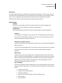
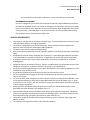
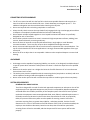
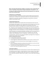
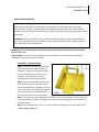
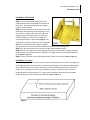
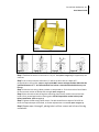
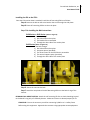
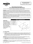
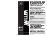
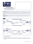
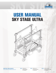
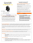
FrenchCreek Production, Inc. 1 User Manual 1791
User Manual – 1791 Self Retracting Lifeline
360° Swivel Roof Anchor
This manual is intended to meet the Manufacturer Instructions as required by ANSI Z359.1 and should be used as
part of an employee training program as required by OSHA.
Instructions for the following product: ATTENTION: This product serves as part of a fall protection system. All users, must read, understand, and follow the manufacturer’s instructions for each and every component of the system. All instructions must be followed for proper application, installation, use, and maintenance of this product. Changing the product, misuse of the product, or failure to follow instructions may result in serious injury or death. If you have any questions concerning the application, installation, use, or maintenance of this product, please contact FrenchCreek Production. FrenchCreek Production, Inc. 2 User Manual 1791
Description: The 1791 Self Retracting life line Roof Anchor is designed for attachment to metal, wood, concrete. The system features a 360 degree swivel that allows the worker freedom to move around the work area. The unit is designed to fit the following FrenchCreek RL‐Series Self Retracting Lifelines: RL25AG, RL25AS, RL25AT, RL30G, RL30SS, RL30T, RL50G, RL50SS, and RL50T. APPLICATIONS PURPOSE: The 1791 is an anchorage connector for a personal fall arrest system, designed to be installed on a metal or wooden roof, and concrete applications. LIMITATIONS: The following application limitations must be considered before using this equipment: CAPACITY: This equipment is designed for use by persons with a combined weight (clothing, tools, etc.) of no more than 310 lbs. (141 kg). No more than one personal protective system may be connected to this device at one time. PERSONAL FALL ARREST SYSTEM: The personal fall arrest system used with this device must meet all applicable OSHA and ANSI requirements. The unit must be mounted directly to the surface. Never work about the unit, and keep free fall distance to a minimum. Never let the self tractable lifeline get caught on obstacles. SWING FALLS: Swing fall occur when the anchorage point is not directly above the point where a fall occurs. The force of striking and object in a swing fall may cause serious injury or death. Minimize swing falls by working as close as possible to the anchorage. Swing falls will significantly increase the clearance required when a self retracting lifeline or other variable length connecting subsystem is used. FALL CLEARANCE: There must be sufficient clearance below the user to arrest a fall before the user strikes the ground or other obstruction. The clearance required is dependent on the following factors: • Elevation of the 1791 • Length of connecting subsystem • Deceleration distance • Movement of harness attachment element (sliding D‐ring) • Worker height • Free fall distance FrenchCreek Production, Inc. 3 User Manual 1791
See personal fall arrest system manufacturer’s instructions for more information. ENVIRONMENTAL HAZARDS: Use of this equipment in areas with environmental hazards may require additional precautions to reduce the possibility of injury to the user or damage to the equipment. Hazards may include, but are not limited to; heat, chemicals, corrosive environments, high voltage power lines, gases, moving machinery, and sharp edges. Contact FrenchCreek if you have questions about using this equipment where environmental hazards exist. GENERAL REQUIREMENTS •
•
•
•
•
•
•
•
•
•
•
•
•
•
•
Users shall be provided with all instructions and warnings. These warnings and instructions must be read and understood prior to using the equipment. This product is designed for personal fall protection. Never use fall protection equipment for purposes other than which it was designed and intended for. This device must only be used by trained personnel. Users must reference ANSI Z359.1 and all applicable regulatory standards pertaining to occupational safety. All equipment must be visually inspected prior to each use. A more thorough inspection procedure is recommended by a competent individual on a regular basis (6 month intervals recommended). A competent person must ensure system compatibility to minimize the potential for accidental disengagement. Equipment must not be altered in any way. Repairs or modifications must be performed only by the equipment manufacturer or persons authorized in writing by the manufacturer. Any products exhibiting deformities, unusual wear, deterioration, or not passing inspection must be immediately removed from service. Any products subjected to fall arresting forces must be removed from service. Fall arrest systems must be rigged to limit the free fall distance (6’ maximum) and ensure that no lower level is struck. Fall arrest systems, when stopping a fall, must limit the maximum arresting force to 1800 lbs. or less. Forces experienced during a fall as well as prolonged suspension may cause bodily injury. In order to minimize this risk of injury, the user shall have a rescue plan and the means at hand to implement it when using this equipment. Always check for obstructions below the work area to make sure the potential fall path is clear. Remember that shock‐absorbers can elongate up to 3 ½’. Environmental hazards must be considered when selecting fall protection equipment. Equipment must not be exposed to chemicals which may have a damaging effect. All synthetic materials must be protected from slag, hot sparks, open flames, or other heat sources. This product should not be used around moving machinery, electrical hazards, sharp edges, and abrasive surfaces. The maximum working load is 310 lbs. unless otherwise labeled. FrenchCreek Production, Inc. 4 User Manual 1791
CONNECTING DEVICES WARNINGS •
•
•
•
•
•
•
•
Tie off in a manner that will limit the free fall to the shortest possible distance and ensure that a lower level will not be struck should a fall occur. Shock‐absorbers can elongate up to 3 ½’. This additional elongation must be considered when choosing a tie‐off point. Do not use lanyards with non‐locking snap hooks or connectors. Always visually check to ensure the snap hooks freely engage the d‐ring or anchorage point and that its keepers are completely closed and locked and are never load bearing. Do not attach multiple lanyards together or tie a lanyard back onto itself unless it is specifically designed for such a connection. Do not allow synthetic materials to come in contact with high temperature surfaces, welding, heat sources, electrical hazards, or moving machinery. Do not tie knots in lanyards or wrap lanyards around sharp, rough edges, or small diameter structural members. Use a cross arm strap or other compatible anchorage connector. Never use a steel cable lanyard for fall arrest unless used in conjunction with a shock‐absorber. The use of a shock‐absorber for fall arrest applications is strongly recommended regardless of the type of lanyard. Never tie off to an object that is not compatible. Make sure that snap hook keepers are never load bearing. ANCHORAGE •
•
•
•
Anchorages must be capable of supporting 5000 lbs. per worker, or be designed, installed and used as part of system which maintains a safety factor of at least 2:1 under the supervision of a qualified person. Make sure the anchor point is at a height that limits the free fall distance to 6’ or less and ensures that no lower level is struck. The anchor point must be compatible with the connecting device (snap hook or carabiner) and must not be capable of causing a load to be applied to the keepers. Never use an anchor point that will not allow the snap hook or carabiner gate to close completely. SYSTEM REQUIREMENTS PERSONAL FALL ARREST SYSTEM: The 1791 is designed for use with FrenchCreek approved components or subsystems. Use of this equipment with non‐approved components may result in incompatibility between equipment, and could affect the reliability and safety of the complete system. Personal fall arrest systems used with this equipment must meet applicable OSHA, state, federal, and ANSI requirements. A full body harness must be worn by the worker when connected to the 1791. As required by OSHA, the personal fall arrest system must be capable of arresting a worker’s fall with a maximum arresting force no greater than 1,800 lbs., and where possible, limit the free fall distance to 6 ft. or less. If the maximum free fall distance of 6 ft (1.83 m) must be exceeded, the employer must be able to document, based on test data, that the maximum permissible arresting forces will not be exceeded, and that the personal fall arrest system will function properly. FrenchCreek Production, Inc. 5 User Manual 1791
When a free fall greater than 6 feet is possible, it is necessary to use a personal fall arrest system incorporating a energy absorber designed specifically for this application. FCP manufactures multiple shock absorbing lanyards specifically designed for this application. Contact FCP for product details. COMPATIBILITY OF COMPONENTS: FrenchCreek equipment is designed for use with FrenchCreek approved components and subsystems only. Substitutions or replacements made with non‐approved components or subsystems may jeopardize compatibility of equipment and may affect the safety and reliability of the complete system. CONNECTORS/CONNECTIONS: Connectors are considered to be compatible with connecting elements when they have been designed to work together in such a way that their sizes and shapes do not cause their gate mechanisms to inadvertently open regardless of how they become oriented. Connectors (hooks, carabiners, and D‐rings) must be capable of supporting at least 5,000 lbs. Connectors must be compatible with the anchorage or other system components. Do not use equipment that is not compatible. Non‐compatible connectors may unintentionally disengage. Connectors must be compatible in size, shape, and strength. Self locking snap hooks and carabiners are required by ANSI Z359.1 AND OSHA. Only use connectors that are suitable to each application. Ensure all connections are compatible in size, shape and strength. Do not use equipment that is not compatible. Ensure all connectors are fully closed and locked. Connectors (snap hooks and carabiners) are designed to be used only as specified in each product’s user’s instructions. Connectors should not be connected: A. To a D‐ring to which another connector is attached. B. In a manner that would result in a load on the gate. C. In a false engagement, where features that protrude from the snap hook or carabiner catch on the anchor and without visual confirmation seems to be fully engaged to the anchor point. D. To each other. E. Directly to webbing or rope lanyard or tie‐back (unless the manufacturer’s instructions for both the lanyard and connector specifically allows such a connection.) F. To any object which is shaped or dimensioned such that the snap hook or carabiner will not close and lock or that accidental disengagement could occur. ANCHORAGE STRENGTH: Anchorages used for attachment of a personal fall arrest system shall be independent of any anchorage being used to support or suspend platforms, and must support at least 5,000 lbs per user attached; or be designed, installed, and used as part of a complete personal fall arrest system which maintains a safety factor of at least 2:1, and is supervised by a qualified person. FrenchCreek Production, Inc. 6 User Manual 1791
INSTALLATION AND USE WARNING: Do not alter or intentionally misuse this equipment. Consult FrenchCreek Production when using this equipment in combination with components or subsystems other than those described in this manual. Some subsystem and component combinations may interfere with the operation of this equipment. Use caution when using this equipment around moving machinery, and sharp edges. WARNING: Consult your doctor if there is reason to doubt your fitness to safely absorb the shock from a fall. Age and fitness seriously affect a worker’s ability to withstand fall. Pregnant women or minors should not use this equipment. BEFORE USE: This equipment must be carefully inspected according to the inspection criteria before each and every use. INSTALLATION: The 1791 may be installed in any steel, wooden, or concrete member meeting the requirements specified for size and strength. Installation: Wooden Roofs
Step 1. Position the anchor so eight of the lag screw holes on the anchor (which are located in a straight line on the base of the unit) are centered over a roof truss (2 x 4 minimum). The roof anchor must be installed at least 6 feet from the gables. Step 2. The holes can be pre‐drilled using a 3/16” drill bit for easier installation and to prevent wood splitting. If splitting or cracking occurs, remove the unit and place elsewhere. Do not reuse the screws included with the unit. Use new screws for each installation. Step 2. The lag screws must engage the center of the truss. Install the eight ¼‐20 x 3 ½‐inch lag screws into the holes located in a straight line on the base unit, through the sheathing and into the roof member. Step 3. Then install the four ¼‐20 x 1 ½ inch lag screws through the corners holes and into the sheathing (Refer to Figure 1). FrenchCreek Production, Inc. 7 User Manual 1791
Installation: Steel Roofs
Step 1. The roof decking must be in place and securely fastened to the roof before installation of the anchor. The metal roofing must be 16 gauge (.060) or thicker material
Step 2. Position the anchor on the roof so it can be fastened to the supporting structure (purlins, truss, etc.) under the metal roof, position the eight self tapping screw holes directly over the supporting structure. Making sure the roof can handle the “Anchorage Strength” requirements (page 5). The 1791 anchor must be at least 6 feet from the gables. Note: If the steel decking has troughs on ridges it may be necessary to shim the area of installation to create a level mounting area. Step 3. Pre‐drill all the holes for the screws, this will make installation easier.
Step 4. Screw in the eight center self‐tapping screws (¼‐20 x 2 inch screws) through the metal decking and into the support structure making sure all eight screws are protruding through the purlin. (Refer to Figure 2) Step 5. Screw in the four corner self‐tapping screws (¼‐20 x 2 inch screws). (Refer to Figure 2) Installation: Concrete
The mounting hole for the FCP 1791 anchor must be located at least 10” from any free edge and far enough away from any obstruction or feature that will keep the carriage from rotating freely when a personal fall arrest system is attached to it. When mounting more than one FCP 1791 anchor on an anchorage, they must be separated by at least 6’. Drill bits used to create the mounting holes must be a nominal ½”. If you have any questions concerning the installation and/or use please contact FrenchCreek Production. (Refer to Figure 3) Figure 3 FrenchCreek Production, Inc. 8 User Manual 1791
Figure 5 Figure 6 Figure 7 Figure 8 Step 1. Position the anchor so the entire 12” by 12” base (Refer to Figure 4)) is supported by the concrete. Step 2. Use a rotary hammer drill and a 1/2” drill bit to drill a hole to a depth of 5”, perpendicular to the surface. (Refer to Figure 5) DO NOT ream or enlarge the hole wider that the specified diameter of ½”. Pre‐Dill and attach one bolt at a time otherwise bolt holes may not line up. Step 3. Clean the hole using a blow out bulb or compressed air. The hole must be free of debris for the concrete anchor to develop full strength. (Refer to Figure 6) Step 4. Drive the anchor bolt through the mounting plate into the anchor hole until the bolt head is firmly seated against the mounting plate. Do NOT expand the anchor bolt by hand before installation. (Refer to Figure 7) Step 5. Tighten the bolt using a 9/16 wrench. The bolt should have a torque of 35‐45 ft.lbs. Once the required torque is achieved, no further adjustments are needed. (Refer to Figure 8) Step 6. Repeat steps 1 through 5, placing bolts in all four corners and in front of the lag screw holes. FrenchCreek Production, Inc. 9 User Manual 1791
Installing the SRL to the 1791: Once the 1791 anchor base is attached, install the self retracting lifeline as follows:
Step A. Remove the bolt on the swivel anchor that runs through the side plates
Step B. Place self retracting lifeline on the main plate
Step C: Re‐Installing the Bolt Instructions: RL30 Series or RL50 Series: (Refer to Figure 9)
Install the bolt through: 1) One side of the anchor plate 2) The handle of the retractable 3) Through the other side of the anchor plate RL25 Series: (Refer to Figure 10)
Install the bolt through: 1) One side of the anchor plate 2) A support spacer (provided) 3) The swivel mount on the RL25 Series retractable 4) The second support spacer (provided) 5) Through the other side of the anchor plate Step D. Secure the nut onto the bolt. Step E. Attach the snap hook of the Self Retracting Lifeline to the back D‐ring of the harness. PERSONAL FALL ARREST SYSTEM: Attach the self retracting life line or shock absorbing lanyard to the dorsal D‐ring only of a full body harness. Make sure harness is donned properly for fit. STRUCTURE: Ensure the structure you will be connecting 5,000 lbs or 2:1 safety factor before using this equipment. Approach the structure using appropriate access equipment. FrenchCreek Production, Inc. 10 User Manual 1791
OTHER CONSIDERATIONS: When working on a structure do not take unnecessary risks such as jumping or reaching too far from the edge. Be aware of all environmental hazards in the area. Do not allow your connecting subsystem to pass under your arms or between your feet. A. SHARP EDGES: Avoid working where the connecting subsystem or other system components will be in contact with, or abrade against, unprotected sharp edges. If working around sharp edges is unavoidable, protection against cutting MUST be provided through the use of a protective cover. B. IN THE EVENT OF A FALL: The responsible party must have a rescue plan and the ability to implement a rescue. C. RESCUE: A Rescue should be performed in the timeliest manner considering all scenarios possible. Training on a rescue should be performed on a periodic basis. Training: It is the responsibility of the user to assure they are familiar with these instructions, and are trained in the correct care and use of this equipment. User must also be aware of the operating characteristics, application limits, and the consequences of improper use of this equipment. INSPECTION: The unit should be inspected before each use and periodically by a competent person other than the user. Inspect the 1791 for cracks, dents, bends, corrosion, or other deformities. Make sure all parts are functioning properly and are not missing. Make sure all adjustment mechanisms are in proper working order. Ensure swivel is working correctly. Ensure all labels are present. Inspect self retracting lifeline per its set of instructions. If at any time inspection reveals any unsafe conditions, remove from service immediately. MAINTENANCE, SERVICING, STORAGE CLEANING: Periodically clean the 1791 using water and a mild soap solution. Use a spray oil to lubricate the thrust bearing and lightly coat the anchor to prevent corrosion. Do not use acids or other caustic chemicals that could damage the system components. Store anchor in a cool dry place. SPECIFICATIONS Material: ¼” & 3/16” Steel Plate Construction Weight: 21 lbs. Plating: powder Coated Safety Yellow Bearing: Steel Thrust Ball Bearing Fasteners: Wood: ¼‐20 x 3 ½ Lag Screws ¼‐20 x 1 ½ Lag Screws Metal: ¼ ‐20 x 2 Self‐Tapping Steel Screws Concrete: ½ Concrete Wedge Bolt